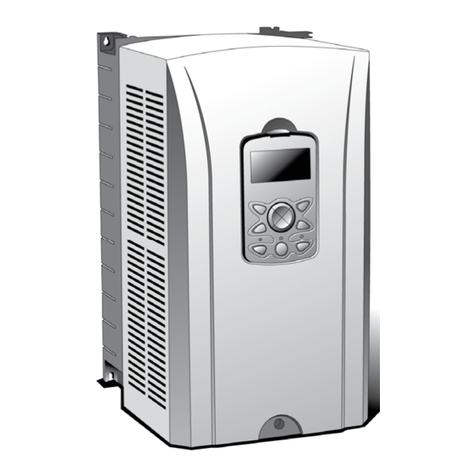
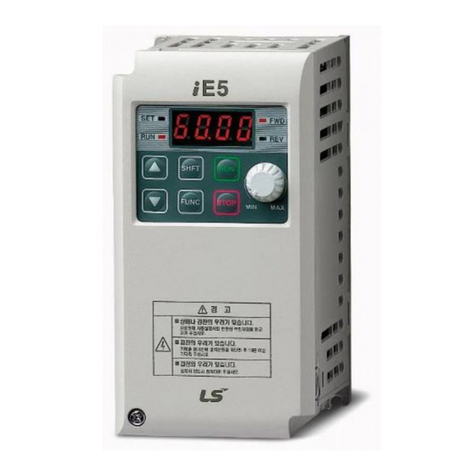
LS Industrial Systems iG5A Series Programming manual

0.4~22kW(200V/400V)
AC Variable Speed Drive
iG5ATroubleshooting Manual
Read this manual carefully before servicing or inspecting this equipment.
Keepthis manual within easy reach for quick reference.
Safety Instructions

1
Quick Reference Table
The following table contains situations frequently encountered by users while working with inverters.
Refer to the typical and practical situations in the table to quickly and easily locate answers to your
questions.
Situation
Reference
The motor is too noisy.
P. 32
I want to review recent fault trip and warning histories.
P. 15
The motor runs too hot.
P. 29
The cooling fan does not work.
P. 33
I want to know how can I keep the inverter when I don`t use it.
P. 44
ERR message is displaying on keypad.
P. 19
I want to initialize the parameter.
P. 13
I want to scrap the inverter.
P. 44
I want to review the input/output module.
P. 38
I want to change the FAN when it exceed replacement period
P. 42
I want to change the carrier frequency.
P. 12
I cannot set the parameter.
P. 28
The motor does not work.
P. 32
The motor stop when it accelerate the speed or connect the load.
P. 30

2
Contents
INTRODUCTION 3
Manual Composition 3
PRODUCTIDENTIFICATION 4
ASSOCIATION MANUAL 4
SAFETYINFORMATION 5
REVISION RECORD 7
1BASIC CHECKLIST 8
1.1 Before You Think It Is Failure 8
1.2 Basic Operations 10
1.3 Parameter Change 12
1.3.1 Carrier Frequency Change 12
1.3.2 InitializingAll Parameters 13
1.3.3 Read and Write Parameters 14
1.4 Fault Trip Monitoring 15
2TROUBLESHOOTING 18
2.1 Trips andWarnings 18
2.1.1 Fault/Warning List 19
2.1.2 Troubleshooting Fault Trips 21
2.2 Troubleshooting Other Faults 28
3MAINTENANCE 34
3.1 Regular Inspection Lists 35
3.1.1 DailyInspections 35
3.1.2 Annual inspections 36
3.1.3 Bi-annual Inspections 37
3.1.4 Checking the Input/Output Modules 38
3.1.5 Replacement of the cooling fan 42
3.2 Storage and disposal 44
3.2.1 Storage 44
3.2.2 Disposal 44

3
Introduction
Manual Composition
1.1 Before You Think It Is Failure
1.2 Basic Operations
1.3 Parameter Change
1.3.1Carrier Frequency Change
1.3.2InitializingAll Parameters
1.3.3Read andWrite Parameters
1.4 Fault Trip Monitoring
2.1 Trips and Warnings
2.1.1Fault/Warning List
2.1.2Troubleshooting Fault Trips
2.2 Troubleshooting Other Faults
3.1 Regular Inspection Lists
3.1.1Daily Inspections
3.1.2Annual inspections
3.1.3Bi-annual Inspections
3.1.4Checking the Input/Output Modules
3.1.5 Replacement of the cooling fan
3.2 Storage and disposal
3.2.1Storage
3.2.2Disposal
There are troubleshooting fault trips &
other faults in these pages.
If problems are not resolved, please
contact your vendor or LSIS.
There are the regular inspection
lists in these pages.
When the problem of inverter occur,
please check the input/output
module that is basic hardware
check method.
When the problem of inverter occur,
you can check the basic checklist
before you think it is failure in these
pages.
check the set-up of parameter using
basic operations first and then
check the trip record.
1 Basic Checklist
Basic Checklist
2 Troubleshooting
3Maintenance

4
Product Identification
Association Manual
iG5Auser manual can be download through the homepage of LSIS.
Link : http://www.lsis.com/support/download/
Modelname
Powersource
specifications
Output
specifications
SV 055 iG5A- 2
004-0.4kw 055-5.5kw
008-0.75kw 075-7.5kw
015-1.5kw 110-11.0kw
022-2.2kw 150-15.0kw
037-3.7kw 185-18.5kw
040-4.0kw 220-22.0kw
Motor capacity
1- Single phase 200~230[V]
2- 3 phase
200~230[V]
4- 3 phase
Input voltage
Series name

5
Safety Information
Read and follow all safety instructions in this manual precisely to avoid unsafe operating conditions,
property damage, personal injury, or death.
Safety symbols in this manual
Danger
Indicates an imminently hazardoussituation which, if not avoided, willresult in severe injury or death.
Warning
Indicates a potentiallyhazardous situation which, if not avoided, couldresult in injuryordeath
Caution
Indicates a potentially hazardous situation that, if not avoided, could result in minor injury or property
damage.
Safety information
Danger
Do not open the cover of the equipment while it is on or operating. Likewise, do not operate the
inverter while the cover is open. Exposure of high voltage terminals or charging area to the external
environment may result in an electric shock. Do not remove anycovers or touch the internal circuit
boards (PCBs) or electricalcontacts on the product when the power is on or during operation.
Doing so may result in serious injury, death, or serious property damage.
Do not open the cover of the equipment even when the power supply to the inverter has been
turnedoff unlessit is necessaryfor maintenance or regular inspection. Opening the cover may
result in an electric shock even when thepower supply isoff.
The equipment may hold charge long after the power supply has been turned off. Use a multi-meter
to make sure that there is no voltage before working on the inverter, motor or motor cable.

6
Warning
This equipment must be grounded for safe and proper operation.
Do not supply power to a faulty inverter. If you find that the inverter is faulty, disconnect the power
supply and have the inverter professionally repaired.
The inverter becomes hot during operation.Avoid touching the inverter until it has cooled to avoid
burns.
Do not allowforeignobjects, such as screws, metal chips, debris, water, or oil to get inside the
inverter.Allowing foreign objects inside the inverter maycause the inverter to malfunction or result in
a fire.
Do not operate the inverter with wet hands. Doing so mayresult in electric shock.
Caution
Do not modify the interior workings of the inverter. Doing so will void the warranty.
The inverter is designed for 3-phase motor operation. Do not use the inverter to operate a single
phase motor.
Do not place heavy objects on top of electric cables. Doing so may damage the cable and result in
an electric shock.

7
Revision Record
Version
Date
Changed main
contents
Association page
V1.0
2015.03
First edition
-

8
1 Basic Checklist
1.1 Before You Think It Is Failure
Items
Check Point
Result
Installation
Location/
Input/Output
voltage
Is the installation location appropriate?
Does the environment meet the inverter’s operating conditions?
Does the power source match the inverter’s rated input?
Is the inverter’s rated output sufficient to supply the equipment?
PowerTerminal
Wiring
Is a circuit breaker installed on the input side of the inverter?
Is the circuit breaker correctly rated?
Are the power source cables correctly connected to the R/S/T
terminals of the inverter?
(Caution: connecting the power source to the U/V/W terminals may
damage the inverter.)
Are the motor output cables connected in the correct phase rotation
(U/V/W)?
(Caution: motors will rotate in reverse direction if three phase cables
are not wired in the correct rotation.)
Are the cables used in the power terminal connections correctly rated?
Is the invertergrounded correctly?
Are the power terminal screws and the ground terminal screws
tightened to their specified torques?
Are the overload protection circuits installed correctly on the motors (if
multiple motors are run using one inverter)?
Is the inverterseparated from the power source by a magnetic
contactor (if a braking resistor is in use)?
Are advanced-phase capacitors, surge protection and electromagnetic
interference filters installed correctly?
(These devices MUST not be installed on the output side of the
inverter.)

1. Basic Checklist
9
Items
Check Point
Result
Control
TerminalWiring
Are STP(shielded twisted pair) cables used for control terminal wiring?
Is the shielding of the STP wiring properlygrounded?
If 3-wire operation is required, are the multi-function input terminals
defined prior to the installation of the control wiring connections?
Are the control cables properly wired?
Are the control terminal screws tightened to their specified torques?
Is the total cable length of all control wiring < 165ft (50m)?
Is the total length of safety wiring < 100ft (30m)?
Miscellaneous
Are optional cards connected correctly?
Is there any debris left inside the inverter?
Are any cables contacting adjacent terminals, creating a potentialshort
circuit risk?
Are the control terminal connections separated from the power
terminal connections?
Have the capacitors been replaced if they have been in use for > 2
years?
Has afuse been installed for the power source?
Are the connections to the motor separated from other connections?

1. Basic Checklist
10
1.2 Basic Operations
About the keypad
The keypad is composed of two main components –the display and the operation (input) keys. Refer to
the following illustration to identify part names and functions
The table below lists the way that the keypad displays characters (letters and numbers).
Display
Keys
SET Indicator
LEDflashes during
parameter configuration and
when the ESCkeyoperates
as the multi-function key
RUN Indicator
LED turns on (steady) during
an operation, and flashes
during acceleration or
deceleration
FWD Indicator
LED turns on
(steady) during
forward operation
REV Indicator
LED turns on
(steady) during
reverse operation
7-Segment Display
Displays current operational
status and parameter
information
.

1. Basic Checklist
11
Operation Keys
The following table lists the names and functions of the keypad’s operation keys.
Key
Name
Description
[RUN] Key
Used to run the inverter (inputs a RUN command).
[STOP/RESET]
Key
STOP: stops the inverter.
RESET: resets the inverter following fault or failure condition.
[▲] Key, [▼] Key
Switch between codes, or to increase or decrease parameter
values.
[◀] Key, [▶] Key
Switch between groups, or to move the cursor during parameter
setup or modification.
[ENT] Key
Used to select, confirm, or save a parameter value.
Caution
Install a separate emergency stop switch in the circuit. The [STOP/RESET] key on the keypad works
only when the inverter has been configured to accept an input from the keypad.

1. Basic Checklist
12
1.3 Parameter Change
1.3.1 Carrier Frequency Change
The following example demonstrates how to configure Carrier Frequency by modifying code H39(Carrier
Frequency) in the Function group 2 from 5.00(Hz) to 10.00(Hz). You can configure the parameters for
different codes in anyother group in exactly thesame way.
Step
Instruction
Keypad Display
1
Go to code H39(Carrier Frequency) in the Function group 2.
2
Press the [ENT] key.
The current Carrier Frequency value (5.00) for code H39 is displayed.
3
Press the [◀] key 2 times to move to the 1s place value.
Number ‘5’ at the 1s place position will flash.
4
Press the [▲] key to change the value to ‘0’ to match the 1s place
value of the target value’10.00’, Press the [◀] key to changethe value
to ‘1’ to match the 10s place value of the target value’10.00’ , and then
press the [ENT] key.
All parameter digits will flash on the display.
5
Press the [ENT] key once again to save the changes.
Code H39 will be displayed. The parameterchange has been
completed.

1. Basic Checklist
13
Adjust motor operational noise by changing carrier frequency settings. Power transistors (IGBT) in the
inverter generate and supply high frequency switching voltage to the motor. The switching speed in this
process refers to the carrier frequency. If the carrier frequency is set high, it reduces operational noise
from the motor, and if the carrier frequency is set low, it increases operational noise from the motor.
Below are advantages and disadvantages according to the sound of the inverter during operation.
Item
Carrier Frequency
LOW
HIGH
Motor noise
↑
↓
Heat
generation
↓
↑
Noise
generation
↓
↑
Leakage
current
↓
↑
1.3.2 InitializingAll Parameters
The following example demonstrates parameter initialization using code H93 (Parameter Initialization) in
the Function group 2. Once executed, parameter initialization will delete all configuration values for all
codes and groups.
Step
Instruction
Keypad Display
1
Go to code H0 in the Function group 2.
2
Press the [ENT] key.
The current parameter value (9) will be displayed.
3
Press the [▼] key to change the first place value to ‘3’ of the target
code, ’93.’

1. Basic Checklist
14
Step
Instruction
Keypad Display
4
Press the [◀] key tomove to the 10s place position.
5
Press the [▲] or [▼] key to change the ‘0’ to ‘9’ of the target
code, ’93.’
6
Press the [ENT] key.
Code H 93 will be displayed.
7
Press the [ENT] key once again.
The current parameter value for code H93 is set to 0 (Do not
initialize).
8
Press the [▲] key to change the value to 1 (All Grp), and then press
the [ENT] key.
The parameter value will flash.
9
Press the [ENT] key once again.
Parameter initialization begins. Parameter initialization is complete
when code H93 reappears on the display.
Note
Following parameter initialization, all parameters are reset to factory default values. Ensure that
parameters arereconfiguredbefore running the inverteragain after an initialization.
1.3.3 Read and Write Parameters
Group
Display
Parameter Name
Setting
Range
Default
Unit
Function
group 2
H91
Parameter read
1
0~1
0
-
H92
Parameter write
1
0~1
0
-
Read and Write Setting Details
Code
Description
H91 Parameter
Read
Copies saved parameters from the inverter to the keypad. Saved parameters on
the keypad will be deleted and replaced with copied parameters.
H92 Parameter Write
Take caution when Parameter write (H92) is executed. By doing this, parameters
in inverter are cleared and parameters in remote keypad are copied to inverter.
* Available on LCD keypad only.

1. Basic Checklist
15
1.4 Fault Trip Monitoring
The following example demonstrates how to monitor fault trip conditions in the Operation group using the
keypad.
Step
Instruction
Keypad Display
1
Refer to the example keypad display.
An over current trip fault has occurred.
2
Press the [ENT] key, and then the [▲] key.
The operation frequency at the time of the fault (30.00Hz) is
displayed.
3
Press the [▲] key.
The output current at the time of the fault (5.0A) is displayed.
4
Press the [▲] key.
The operation status at the time of the fault is displayed.ACC on the
displayindicates that the fault occurred during acceleration.
5
Press the [STOP/RESET] key.
The inverter resets and the fault condition is cleared. The frequency
reference is displayed on the keypad.
Over Current
Trip

1. Basic Checklist
16
The following example demonstrates how to monitor fault trip record.
Group
Display
Parameter Name
Setting
Range
Default
Unit
Function
group 2
H 1
[Fault history 1]
-
~
H 5
[Fault history 5]
-
H 6
[Reset fault history]
-
0 ~ 1
0
Up to 5 faults information is stored. a maximum of 5 fault trip records can be retrieved as shown in the
following example.
Record of fault types
Operating status at fault
Accel/Decel
Information
Frequency
Current

1. Basic Checklist
17
Fault types
Frequency
Current
Accel/Decel
Information
Fault duringAccel
Fault during Decel
Fault during constant run
Reset fault record
Change the value to
‘1’ and then press
the [ENT] key.

18
2 Troubleshooting
This chapter explains how to troubleshoot a problem when inverter protective functions, fault trips,
warning signals, or a fault occurs. If the inverter does not work normally after following the suggested
troubleshooting steps, please contact the LSIS customer servicecenter.
2.1 Trips and Warnings
When the inverter detects a fault, it stops the operation (trips) or sends out a warning signal. When a trip
or warning occurs, the keypad displays the information briefly. If the LCD keypad is used, detailed
information is shown on the LCD display. Users can read trip message when a fault occurs during
operation in nOn code of drive group. Up to 5 trips information is stored.
The fault conditions can be categorized as follows:
•Level: When the fault is corrected, the trip or warning signal disappears and the fault is not saved in the
fault history.
•Latch: When the fault is corrected and a reset input signal is provided, the trip or warning signal
disappears.
•Fatal: When the fault is corrected, the fault trip or warning signal disappears only after the user turns off
the inverter, waits until the charge indicator light goes off, and turns the inverter on again (If the inverter is
still in a fault condition after powering it on again, please contact the supplier or the LSIS customer
service center).

2. Troubleshooting
19
2.1.1 Fault/Warning List
The following listshows the types of faults and warningsthatcan occur while using the iG5A inverter.
Category
LCD Display
Details
Page
Major fault
Latch type
Over current trip
P. 21
ARM short current fault trip
P. 22
Ground fault trip
P. 22
Inverter overload fault trip
P. 23
Overload fault trip
P. 23
Over heat fault trip
P. 23
Output open-phase fault trip
P. 24
Over voltage trip
P. 24
Electronic thermal
P. 25
Input phase loss
-
Self-diagnostic malfunction
-
Parameter save error
P. 27
Communication
Error
P. 27
Remote keypad communication
error
P. 26
Keypad error
P. 27
Cooling fan fault
P. 24
External faultAcontact input
P. 26
External fault B contact input
P. 26
NTC Open
P. 27
Other manuals for iG5A Series
1
Table of contents
Other LS Industrial Systems Inverter manuals
LS Industrial Systems
LS Industrial Systems SV-iS7 Series User manual

LS Industrial Systems
LS Industrial Systems LSLV-S100 User manual

LS Industrial Systems
LS Industrial Systems STARVERT iG5A User manual
LS Industrial Systems
LS Industrial Systems iS7 RAPIEnet User manual

LS Industrial Systems
LS Industrial Systems SV-iE5 Series User manual
LS Industrial Systems
LS Industrial Systems SV-iV5 Series User manual
LS Industrial Systems
LS Industrial Systems SV iC5 Series Operation manual