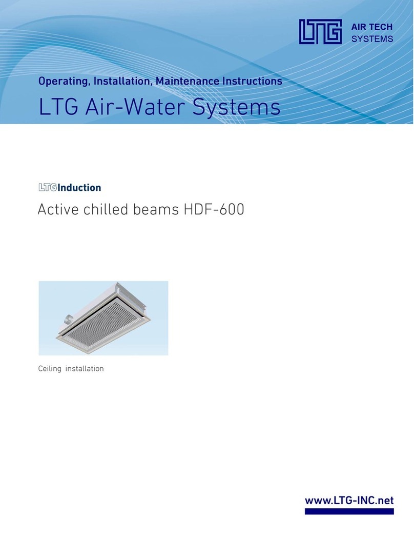
LTG feel cool HDC User manual

The Innovation Company
LTG Aktiengesellschaft
Original Instructions for Installation, Use
and Maintenance
Active Chilled Beam HDC
LTG Aktiengesellschaft
D - 70435 Stuttgart, Grenzstraße 7
D -- 70405 Stuttgart, Postfach 40 05 25
+49 (0711) 82 01-0 Fax +49 (0711) 82 01-720
Internet: http://www.LTG-AG.de
E-Mail: info@LTG--AG.de
AG--B 213.1e (Feb. 10)


Original Instructions for Installation, Use and Maintenance
Active Chilled Beam Type HDC
Section:
Page:
Date:
AG--B 213.1e
3
Feb. 2010
The Innovation Company
LTG Aktiengesellschaft
ELTG Aktiengesellschaft ⋅Grenzstraße 7 ⋅D-70435 Stuttgart ⋅+49 (0711) 8201-0 ⋅Fax -720
Internet: http://www.LTG-AG.de ⋅E-Mail: info@LTG-AG.de ⋅Printed in Germany ⋅Ausgaben mit früherem
Datum werden hiermit ungültig ⋅Technische Änderungen vorbehalten ⋅Former editions are invalid ⋅Subject to technical modifications.
Table of contents
Safety Instructions 5
1 Transport and Storage 7
1.1 Transport Instructions 7
1.2 Storage 7
2 Function 8
2.1 Intended Use 8
3 Technical Specifications 9
3.1 Dimensions 9
3.2 Performance Data 11
3.3 Caloric Output Data 15
3.4 Acoustic Data 15
3.5 Hydraulic Data 15
3.6 Weight 15
4 Installation 16
4.1 Notes 16
4.2 Suspension 16
4.3 Water Connections 17
4.4 Primary Air 23
4.5 Check after Installation 26
5FirstUse 27
6 Operation, Maintenance and Repair 27
6.1 Heat Exchanger, Water Connections and Condensate Tray 27
6.2 Filter 27
6.3 Two--pipe and Four--pipe System 28
6.4 Selecting the Room Temperature 28
6.5 Excessive Noise and Draugt 28
6.6 Out--of--service Times 28
6.7 Repair 29
6.8 Trouble Shooting and Corrective Action 30
6.9 Maintenance Intervals of the Individual Components 33
7 Spare Parts 34
8 Decommissioning and Deposal 34


Original Instructions for Installation, Use and Maintenance
Active Chilled Beam Type HDC
Section:
Page:
Date:
AG--B 213.1e
5
Feb. 2010
The Innovation Company
LTG Aktiengesellschaft
ELTG Aktiengesellschaft ⋅Grenzstraße 7 ⋅D-70435 Stuttgart ⋅+49 (0711) 8201-0 ⋅Fax -720
Internet: http://www.LTG-AG.de ⋅E-Mail: info@LTG-AG.de ⋅Printed in Germany ⋅Ausgaben mit früherem
Datum werden hiermit ungültig ⋅Technische Änderungen vorbehalten ⋅Former editions are invalid ⋅Subject to technical modifications.
Carefully read the safety instructions before using any LTG induction unit.
Always follow the safety instructions!
Safety Instructions
The units meet any pertinent safety standards.
The installation and maintenance of air conditioning units may be dangerous because of high
pressures andelectrical components being alive. Therefore, the installation, maintenance, andre-
pair must be performed by qualified and trained staff only.
Safety instructions in the technical documentation and on unit labels must be followed at all times.
Die elektrischen Anschlüsse eventueller Regelgeräte dürfen nur von hierzu befugten Personen
entsprechend den örtlichen Sicherheitsvorschriften hergestellt, abgebaut oder geändert werden.
Do not open the unit for cleaning, maintenance, or repair and do not remove covers and casings
(air diffuser) unless all conducting lines have been completely disconnected.
The standard version of the heat exchangers is designed for an operating pressure of 10 bar (test
pressure 16 bar). High water pressures may be hazardous. Higheroperating pressures,therefore,
require LTG’s express permission. Wear safety glasses.
Be careful when performing work on the heat exchangers. Blades and housing parts are sharp--
edged. Wear gloves during work and handling.
Be careful when working overhead and provide protection against parts falling from above.
The casing on site also serves as a protection and should be removed for maintenance and clea-
ning only.
Avoid any additional load to the unit or the suspensions since stability might be insufficient.
In the heating mode a temperature of up to 80 _C may be achieved. Water--carrying parts may
be hot so do not touch with your bare hands to avoid burns.
The unit must be checked by an expert immediately
- if it has been mechanically damaged or is suffering from a water damage,
- if the suspension or the casing show clear signs of corrosion or ageing.
Do not put the unit back into operation before all necessary maintenance and repair has been per-
formed!


Original Instructions for Installation, Use and Maintenance
Active Chilled Beam Type HDC
Section:
Page:
Date:
AG--B 213.1e
7
Feb. 2010
The Innovation Company
LTG Aktiengesellschaft
ELTG Aktiengesellschaft ⋅Grenzstraße 7 ⋅D-70435 Stuttgart ⋅+49 (0711) 8201-0 ⋅Fax -720
Internet: http://www.LTG-AG.de ⋅E-Mail: info@LTG-AG.de ⋅Printed in Germany ⋅Ausgaben mit früherem
Datum werden hiermit ungültig ⋅Technische Änderungen vorbehalten ⋅Former editions are invalid ⋅Subject to technical modifications.
1. Transport and Storage
The unit requires dry and dust--free conditions during transport, storage, installation, and operation.
The unit is supplied in corrugated board boxes secured with straps.
Units are stacked on Euro or single trip pallets and secured with straps. Pallets may be moved using forklifts
or cranes.
Do not remove the packaging unlessimmediately prior to installation on site to protect the unit from pollution
and damages.
LTG Aktiengesellschaft will not take responsibility for any pollution of or
damages to the unit.
1.1 Transport Instructions
Handle units appropriately and with care during transport.
Do not throw, let drop to the ground or bump into other items or walls.
Make sure that units are safely fastened during transport and avoid damage through other items.
It is recommended to always have units handled by at least two persons.
The packaging is not weather--resistant.
1.2 Storage
Make sure that units are entirely protected against weathering, humidity, and other adverse conditions that
might result in damages during storage.
The storage location must meet the following climatic requirements:
Temperature between +5 _C and +55 _C with a relative humidity of 90 % max. (non--condensing).

Original Instructions for Installation, Use and Maintenance
Active Chilled Beam Type HDC
Section:
Page:
Date:
AG--B 213.1e
8
Feb. 2010
The Innovation Company
LTG Aktiengesellschaft
ELTG Aktiengesellschaft ⋅Grenzstraße 7 ⋅D-70435 Stuttgart ⋅+49 (0711) 8201-0 ⋅Fax -720
Internet: http://www.LTG-AG.de ⋅E-Mail: info@LTG-AG.de ⋅Printed in Germany ⋅Ausgaben mit früherem
Datum werden hiermit ungültig ⋅Technische Änderungen vorbehalten ⋅Former editions are invalid ⋅Subject to technical modifications.
2. Function
The Active Chilled Beam HDC is specifically designed for installation in false ceilings. In the cooling mode
room air is heated at the façade, entrained into the unit, cooled and recirculated to the space.
Primary air flow from internal metal nozzles, induces room air through a heat exchanger where it is cooled
or heated. The primary air is mixed with the heated or cooled secondary air and delivered into the room.
Hygienic operation is achieved by avoiding dehumidification of the secondary air.
min. 2.8 m
min. 3.00 m
Facade
Section through a typical office room, length : 6 m, height : 2.8 m. Schematic illustration of indoor air flow.
Cooling mode
Room air heated at façade is drawn directly into the units where it is cooled. Supply air is diffused along the
ceiling, mixes with the ambient air to reduce air speed and temperature difference.
High thermal comfort up to 50 W/m2or 7.5 m3/hm2(primary air).
2.1 Intended Use
The induction unit type HDC is intended for use in closed rooms.
It is designed for ambient temperatures of +5 _Cto+40_C and a maximum relative humidity of up to 90%
(non--condensing).
The maximum admissible supply temperature is, therefore, limited to +80 _C.
Any other operating conditions require the express and written permission of LTG Aktiengesellschaft.
LTG Aktiengesellschaft does not assume responsibility for any damages resulting from unintended use.

Original Instructions for Installation, Use and Maintenance
Active Chilled Beam Type HDC
Section:
Page:
Date:
AG--B 213.1e
9
Feb. 2010
The Innovation Company
LTG Aktiengesellschaft
ELTG Aktiengesellschaft ⋅Grenzstraße 7 ⋅D-70435 Stuttgart ⋅+49 (0711) 8201-0 ⋅Fax -720
Internet: http://www.LTG-AG.de ⋅E-Mail: info@LTG-AG.de ⋅Printed in Germany ⋅Ausgaben mit früherem
Datum werden hiermit ungültig ⋅Technische Änderungen vorbehalten ⋅Former editions are invalid ⋅Subject to technical modifications.
3. Technical Specifications
3.1 Dimensions
Dimensions 4-pipe-System, flanged Installation
primary air
air inlet air outlet
Hole 8.5 for threaded rod M6
KKW--VL = cooling -- water inlet
KKW--RL = cooling -- water return
HZG--VL = heating -- water inlet
HZG--RL = heating -- water return
“X”
340 ±1.5
286 ±1.5
160 36
HZG--VL
KKW--VL
KKW--RL
HZG--RL
73 73 48
101 35
38 31
240
17
Ø 100
View “X”
Plug-in connection
12 mm Ø x 0.75
1190 ±1.5
16
Unit suspension 1069 +3
Unit length 1158
Total length of outlet 1240 ±1.5
575.5

Original Instructions for Installation, Use and Maintenance
Active Chilled Beam Type HDC
Section:
Page:
Date:
AG--B 213.1e
10
Feb. 2010
The Innovation Company
LTG Aktiengesellschaft
ELTG Aktiengesellschaft ⋅Grenzstraße 7 ⋅D-70435 Stuttgart ⋅+49 (0711) 8201-0 ⋅Fax -720
Internet: http://www.LTG-AG.de ⋅E-Mail: info@LTG-AG.de ⋅Printed in Germany ⋅Ausgaben mit früherem
Datum werden hiermit ungültig ⋅Technische Änderungen vorbehalten ⋅Former editions are invalid ⋅Subject to technical modifications.
Dimensions 2-pipe-System, flanged Installation
primary air
air inlet
“X”
340 ±1.5
286 ±1.5
160 36
KKW--VL
KKW--RL
72 121.5
167
38
240
17
Ø100
Ø8.5für
Gewindestange M6
air outlet
KKW--VL = cooling -- water inlet
KKW--RL = cooling -- water return
View “X”
16
1190 ±1.5
Unit suspension 1069 +3
Unit length 1158
Total length of outlet 1240 ±1.5
575.5
Plug-in connection
12 mm Ø x 0.75

Original Instructions for Installation, Use and Maintenance
Active Chilled Beam Type HDC
Section:
Page:
Date:
AG--B 213.1e
11
Feb. 2010
The Innovation Company
LTG Aktiengesellschaft
ELTG Aktiengesellschaft ⋅Grenzstraße 7 ⋅D-70435 Stuttgart ⋅+49 (0711) 8201-0 ⋅Fax -720
Internet: http://www.LTG-AG.de ⋅E-Mail: info@LTG-AG.de ⋅Printed in Germany ⋅Ausgaben mit früherem
Datum werden hiermit ungültig ⋅Technische Änderungen vorbehalten ⋅Former editions are invalid ⋅Subject to technical modifications.
3.2 Performance Data
Size 1000 --4--pipe--system -- cooling and heating
V
[m3/h]
p
[Pa]
LA18
[dB(A)]
LwA
[dB(A)]
QP/t
[W/K]
Qk/t
[W/K]
Qk1
[W]
QP1
[W]
wok /pw
[kg/h]/[kPa]
Qh/t
[W/K]
Qh2
[W]
woh /pw
[kg/h]/[kPa]
40 50 22 28 13 23 230 130
100 / 6.3
18 720
100 / 2.4
50 77 23 29 17 28 280 170 22 880
60 110 26 32 20 34 340 200 26 1040
70 150 29 35 23 37 370 230 29 1160
80 195 33 39 27 42 420 270 32 1280
Size 1000 --2--pipe--system -- cooling or heating
V
[m3/h]
p
[Pa]
LA18
[dB(A)]
LwA
[dB(A)]
QP/t
[W/K]
Qk/t
[W/K]
Qk1
[W]
QP1
[W]
wok /pw
[kg/h]/[kPa]
Qh/t
[W/K]
Qh2
[W]
woh /pw
[kg/h]/[kPa]
40 50 22 28 13 24 240 130
100 / 8.5
20 800
100 / 6.2
50 77 23 29 17 30 300 170 25 1000
60 110 26 32 20 36 360 200 30 1200
70 150 29 35 23 40 400 230 33 1320
80 195 33 39 27 45 450 270 37 1480
Data is based on the unit with the inlet/outlet grille installed.
The induction air temperature at the unit is usually 1--2 K higher than the room temperature.
Standard water flow rate for heating and cooling: 100 kg/h. Correction valuesfor other flow rates see the follo-
wing pages.
1 Water supply temperature: 16 _C W; room temperature at a height of 1.1 m: 26 _C;
non-condensing operation.
2 Water supply temperature: 60 _C; air inlet temperature: 20 _C.
Legend
V-- flow rate (¦10%)
p-- static pressure at primary air spigot
LA18 -- sound pressure level (¦3dB)
LwA -- sound power level (¦3 dB) (without ceiling)
QP-- primary cooling capacity (fresh air) (¦5%)
Qk-- cooling capacity, secondary
(heat exchanger) (¦5%)
t-- temperature difference between room air
and water supply
wok -- standard flow rate at cooling capacity
pw-- water-side pressure loss
Qh-- heating capacity, secondary (¦5%)
woh -- standard flow rate at heating capacity

Original Instructions for Installation, Use and Maintenance
Active Chilled Beam Type HDC
Section:
Page:
Date:
AG--B 213.1e
12
Feb. 2010
The Innovation Company
LTG Aktiengesellschaft
ELTG Aktiengesellschaft ⋅Grenzstraße 7 ⋅D-70435 Stuttgart ⋅+49 (0711) 8201-0 ⋅Fax -720
Internet: http://www.LTG-AG.de ⋅E-Mail: info@LTG-AG.de ⋅Printed in Germany ⋅Ausgaben mit früherem
Datum werden hiermit ungültig ⋅Technische Änderungen vorbehalten ⋅Former editions are invalid ⋅Subject to technical modifications.
Water-side Pressure Loss and Cooling Capacity with different water Flow Rates
Type HDC, 4-pipe System, standard Flow Rate 100 kg/h
40 90 140 190
0.5
1
2
5
10
20
Waterflowratew [kg/h]
Water--side pressure loss pw[kPa]
20 40 60 80 100 120 140
40
60
80
100
120
Water flow rate in % of the standard flow rate
Secondary cooling capacity in % of the nominal capacity Qk
Note: The minimum flow rate must be at
least 20% of the standard flow rate in the
cooling mode
(to ensure water--side pressure equalization)

Original Instructions for Installation, Use and Maintenance
Active Chilled Beam Type HDC
Section:
Page:
Date:
AG--B 213.1e
13
Feb. 2010
The Innovation Company
LTG Aktiengesellschaft
ELTG Aktiengesellschaft ⋅Grenzstraße 7 ⋅D-70435 Stuttgart ⋅+49 (0711) 8201-0 ⋅Fax -720
Internet: http://www.LTG-AG.de ⋅E-Mail: info@LTG-AG.de ⋅Printed in Germany ⋅Ausgaben mit früherem
Datum werden hiermit ungültig ⋅Technische Änderungen vorbehalten ⋅Former editions are invalid ⋅Subject to technical modifications.
Water-side Pressure Loss and Heating Capacity with different water Flow Rates
Type HDC, 4-pipe System, standard Flow Rate 100 kg/h
40 90 140 190
0.2
0.5
1
2
5
10
15
Water flow rate w [kg/h]
Water--side pressure loss pw[kPa]
50 70 90 110 130 150
40
60
80
100
120
Note: The minimum flow rate must be at
least 40% of the standard flow rate in the
heating mode
(to ensure water--side pressure equalization)
Water flow rate in % of the standard flow rate
Secondary heating capacity in % of the nominal capacity Qh

Original Instructions for Installation, Use and Maintenance
Active Chilled Beam Type HDC
Section:
Page:
Date:
AG--B 213.1e
14
Feb. 2010
The Innovation Company
LTG Aktiengesellschaft
ELTG Aktiengesellschaft ⋅Grenzstraße 7 ⋅D-70435 Stuttgart ⋅+49 (0711) 8201-0 ⋅Fax -720
Internet: http://www.LTG-AG.de ⋅E-Mail: info@LTG-AG.de ⋅Printed in Germany ⋅Ausgaben mit früherem
Datum werden hiermit ungültig ⋅Technische Änderungen vorbehalten ⋅Former editions are invalid ⋅Subject to technical modifications.
Water-side Pressure Loss and Cooling Capacity with different water Flow Rates
Type HDC, 2-pipe System, standard Flow Rate 100 kg/h
40 90 140 190
0.5
1
2
5
10
20
20 40 60 80 100 120 140
40
60
80
100
120
Waterflowratew [kg/h]
Water--side pressure loss pw[kPa]
Water flow rate in % of the standard flow rate
Secondary cooling capacity in % of the nominal capacity Qk

Original Instructions for Installation, Use and Maintenance
Active Chilled Beam Type HDC
Section:
Page:
Date:
AG--B 213.1e
15
Feb. 2010
The Innovation Company
LTG Aktiengesellschaft
ELTG Aktiengesellschaft ⋅Grenzstraße 7 ⋅D-70435 Stuttgart ⋅+49 (0711) 8201-0 ⋅Fax -720
Internet: http://www.LTG-AG.de ⋅E-Mail: info@LTG-AG.de ⋅Printed in Germany ⋅Ausgaben mit früherem
Datum werden hiermit ungültig ⋅Technische Änderungen vorbehalten ⋅Former editions are invalid ⋅Subject to technical modifications.
3.3 Caloric Output Data
Caloric output data were determined at a test stand in the LTG test lab.
Data are valid if the following applies:
- unit at operating temperature, steady--state condition
- steady--state condition during measurements
- no condensation at the heat exchanger in the cooling mode
- water without additives (drinking water quality)*
- water supply temperatures from 12 _Cto16_C in the cooling mode and 50 _C--60_C in the heating mode.
Parameters used:
- specific heat capacity of the water 4186 J/(kgK)
- specific heat capacity of the air 1004 J/(kgK)
- air density 1.2 kg/m3
To ensure easy transferability, the specific caloric outputs -- i.e. the absolute caloric outputs in relation to the
temperature difference between water intake and induction air before entering the heat exchanger -- are given.
The outputs given in the chart do apply with specific nominal flow rates only. These are stated for each type
and size.
The correction charts give a graphic illustration of how outputs change with other flow rates compared to no-
minal flow rate output.
Flow rates have been determined through calculation and may vary by about 10%.
* Addition of ethylene glycol to lower the freezing point:
To lower the freezing point, cooling water is often addedsome ethyleneglycol. The lower specific thermal
capacity of the mixture reduces the unit’s cooling capacity.
3.4 Acoustic Data
Acoustic data have been determined in a reverberation chamber in the LTG test lab.
The technical data sheet contain the A weighted sound pressure levels LA18 for different primary air flow ra-
tes/static pressures at primary air socket.
Sound pressure levels apply to a room absorption surface of 18 m2which equals a room absorption of about
6 dB(A). Thus, sound power levels may easily be calculated.
LWA =L
A18 + 6 dB(A)
The data given apply to one unit, i.e. one room axle. If more than one unit is installed in the same room, the
sound pressure level will rise accordingly.
Increase in sound level with several sound sources of the same type:
Number of sound sources of the same type 1 2 3 4
Sound level increase [dB] 3 5 6
Measuring accuracy is 10%.
3.5 Hydraulic Data
Heat exchangers are approved for an operating pressure of 10 bar max. (test pressure 16 bar).
Pressures exceeding 10 bar require the express permission of LTG.
Water--side pressure losses have been measured directly at the heat exchanger connections. Further resi-
stances will have to be added.
Measuring accuracy is 10%.
3.6 Weight
Standard units (without water) 17 kg, diffuser 6 kg.

Original Instructions for Installation, Use and Maintenance
Active Chilled Beam Type HDC
Section:
Page:
Date:
AG--B 213.1e
16
Feb. 2010
The Innovation Company
LTG Aktiengesellschaft
ELTG Aktiengesellschaft ⋅Grenzstraße 7 ⋅D-70435 Stuttgart ⋅+49 (0711) 8201-0 ⋅Fax -720
Internet: http://www.LTG-AG.de ⋅E-Mail: info@LTG-AG.de ⋅Printed in Germany ⋅Ausgaben mit früherem
Datum werden hiermit ungültig ⋅Technische Änderungen vorbehalten ⋅Former editions are invalid ⋅Subject to technical modifications.
4. Installation
4.1 Notes
Shipping of Unit
If not required otherwise, units are shipped in wrapping boxes which may also serve as a protection during
installation. Boxes must be stored in an upright position as indicated by the arrow on the box. The packaging
is disposable and not to be returned to LTG.
Timing of Installation
Installation of the units should not be performed unless the prefabricated floor has been finished, the window
sill installed, the intermediate ceiling and any other dust producing work completed.
Handling of Units
Handle units with care during transport and installation. Avoid dropping to the ground.
4.2 Suspension
Please observe the following when installing air conditioning units:
- For reasons of stability and rigidity, never use bolts with a property classinferior to the one indicated. Fixing
elements are not included in the delivery.
- Do not use other than the holes provided for to fasten fixing elements.
- Do not use the air conditioning units as load--bearing elements for other components and avoid any other
loading.
Fixing elements must be chosen in a way to ensure that any sound transmis-
sion is avoided.

Original Instructions for Installation, Use and Maintenance
Active Chilled Beam Type HDC
Section:
Page:
Date:
AG--B 213.1e
17
Feb. 2010
The Innovation Company
LTG Aktiengesellschaft
ELTG Aktiengesellschaft ⋅Grenzstraße 7 ⋅D-70435 Stuttgart ⋅+49 (0711) 8201-0 ⋅Fax -720
Internet: http://www.LTG-AG.de ⋅E-Mail: info@LTG-AG.de ⋅Printed in Germany ⋅Ausgaben mit früherem
Datum werden hiermit ungültig ⋅Technische Änderungen vorbehalten ⋅Former editions are invalid ⋅Subject to technical modifications.
4.3 Water Connections
Remove the heat exchanger plugs prior to water connection!
Units are provided with heat exchangers with copper tubes and aluminum blades for 4--pipe operation with
separate heating and cooling circuits or for 2--pipe operation.
The heat exchangers have been approved for a maximum operating pressure of 10 bar
(other pressures on request).
Depending on the unit type, water connections are supplied in the following versions:
1. copper fitting with 12 mm outer diameter.
This connection is only suitable for flexible connection with quick coupling.
Always follow the installation instructions for the water connections attached
to each unit.
Connections must be strainless.
Connecting lines must be able to expand.
Attention:
Prior to allowing water to enter the unit the flexible water connection hoses
will have to be checked for proper and leakproof fixation. Even though hoses
to the heat exchanger are preinstalled, fixations might have loosened during
transport or installation of the unit on site.
You may use off--the--shelf control valves and shut--off valves.
When tightening the fittings, avoid damaging the heat exchanger pipes through bending or twisting.
Pipe fittings must always be flush.
In order to adjust the water volume specified in the selection data, a regulating device or restricting olive will
be required. If identical units with exactly the same water volume and pressure losses are used, an individual
regulating device for each unit is superfluous. In this case, one regulating device for the entire line may be
sufficient. Otherwise, a regulating device will be required for each heat exchanger.
If removal of a heat exchanger without draining the entire system is a requirement, two orfour isolation valves
will have to be provided for each unit. You may use off--the--shelf shut--off valves.
The unit fitting will only be provided with an integrated vent if specifically asked for. The water speed inside
the heat exchanger is usually sufficient to carry along air bubbles and one ventilation device per line is there-
fore appropriate. In a case of emergency, the line may be ventilated by slightly loosening the standard fitting
of the unit.
Included in the unit price and also in general provided with the unit -- (unless special fittings such as transi-
tions, straight-way or angle valves or hose connections are ordered) isa complete compressionfitting forunit-
side water connection, appropriate to take copper pipes with a 12 mm outer diameter, wall thickness of
0.7 -- 1.0 mm, suitable for connecting hoses. The union nut is fixed to the heat exchanger pipe’s flared end,
while olive and banjo bolt will be delivered in packs of 2 or 4 -- according to type of unit -- in a bag attached
to the unit.
Exception: The water connections of units HFG--4 and HFS--4 are provided with a sleeve with fixed internal
thread or a soldered--on smooth 12 mm tube to take a quick coupling.
Due to possible condensation, the connections to the heat exchanger for cooling should be insulated, e.g. using
Armaflex insulation.

Original Instructions for Installation, Use and Maintenance
Active Chilled Beam Type HDC
Section:
Page:
Date:
AG--B 213.1e
18
Feb. 2010
The Innovation Company
LTG Aktiengesellschaft
ELTG Aktiengesellschaft ⋅Grenzstraße 7 ⋅D-70435 Stuttgart ⋅+49 (0711) 8201-0 ⋅Fax -720
Internet: http://www.LTG-AG.de ⋅E-Mail: info@LTG-AG.de ⋅Printed in Germany ⋅Ausgaben mit früherem
Datum werden hiermit ungültig ⋅Technische Änderungen vorbehalten ⋅Former editions are invalid ⋅Subject to technical modifications.
The water connection side is to be specified when ordering the unit. Some units offer a possibility to still
change the side during installation by removing 4 bolts.
Execute the heat exchanger connection as follows:
-- Vertical heat exchangers: water supply below, water return above
-- Horizontal heat exchangers: unit’s front side: water supply, unit’s back side: water return
Example for water connection using flexible hose
(Quick coupling connection to heat exchangers)
Hose without insulation. For insulated hoses, dimensions will change accordingly
(10 mm Armaflex insulation).
Hose for connection to heat exchanger with smooth tube end diameter 12 mm,
connection types: quick coupling, quick coupling with venting
Different hose connections, thread diameter acc. to customer requirements or standard 1/2”
min.150
min.35
min.35
min.R50
ca.100
ca.200
min.150
min.35
min.35
min.R50
ca.100
ca.200
Ø17 DN 12
Ø17 DN 12
Example for water connection
using transition - LTG description VSG 10/ 2 EH (venting) -,
straight-way valve and flexible hose
min.35
min.35
min.R50
Ø15 DN 10
Hose without insulation. For insulated hoses, dimensions will change accordingly.
Hose for connection to angle or straight-way valve,
connection type: AGK, external thread, tapered 1/2”
Different hose connections, thread diameter acc. to customer requirements or standard 1/2”

Original Instructions for Installation, Use and Maintenance
Active Chilled Beam Type HDC
Section:
Page:
Date:
AG--B 213.1e
19
Feb. 2010
The Innovation Company
LTG Aktiengesellschaft
ELTG Aktiengesellschaft ⋅Grenzstraße 7 ⋅D-70435 Stuttgart ⋅+49 (0711) 8201-0 ⋅Fax -720
Internet: http://www.LTG-AG.de ⋅E-Mail: info@LTG-AG.de ⋅Printed in Germany ⋅Ausgaben mit früherem
Datum werden hiermit ungültig ⋅Technische Änderungen vorbehalten ⋅Former editions are invalid ⋅Subject to technical modifications.
Example for water connection using valve and flexible hose
(straight and 90
_
variant)
Hose without insulation. For insulated hoses, dimensions will change accordingly.
(10 mm Armaflex insulation
Hose for connection to angle or straight-way valve,
Connection type AGK, external thread, tapered 1/2”
Different hose connections, thread diameter acc. to customer requirements or standard 1/2”
Connection for direct screwing into the heat exchanger in case of angle connection,
Connection type: double nipple 1/2”--1/2”; UFD hose connection, 1/2” flat seal union nut
Example for water connection for direct screwing into the heat exchanger
Hose without insulation. For insulated hoses, dimensions will change accordingly.
Connection for direct screwing into the heat exchanger
Connection type: AGK, external thread, tapered 1/2”
Different hose connections, thread diameter acc. to customer requirements or standard 1/2”
min.150
min. 35
min. R 50
Ø17 DN 12
min.150
min. 35
min. R 50
Ø17 DN 12

Original Instructions for Installation, Use and Maintenance
Active Chilled Beam Type HDC
Section:
Page:
Date:
AG--B 213.1e
20
Feb. 2010
The Innovation Company
LTG Aktiengesellschaft
ELTG Aktiengesellschaft ⋅Grenzstraße 7 ⋅D-70435 Stuttgart ⋅+49 (0711) 8201-0 ⋅Fax -720
Internet: http://www.LTG-AG.de ⋅E-Mail: info@LTG-AG.de ⋅Printed in Germany ⋅Ausgaben mit früherem
Datum werden hiermit ungültig ⋅Technische Änderungen vorbehalten ⋅Former editions are invalid ⋅Subject to technical modifications.
4.3.1 Instructions for Installation of Water Connections Using Flexible Hoses
Warranty will only apply if the following instructions are observed and if in-
stallation is performed in compliance with DIN--EN regulations.
In particular, corrosive, electrochemical, and bacteriological charges are to
be excluded taking appropriate preventive measures.
- Pressure and exposition to heat may re-
sult in slight elongation of the hose.
Therefore, newly placed hoses must con-
sider such potential elongation.
- Do not fall below the admissible bending
radius Rmin (chart), neither during trans-
port, nor during installation or when in-
stalled.
If it should turn out impossible to keep
the admissible bending radius, choose a
different installation type.
- For minimum length see chart below.
If the hose is being placed by bending it,
check whether there is sufficient hose
length to allow for an open bow in order
to avoid kinking and destruction of the
hose at the connecting points.
- Absolutely avoid distorting or kinking
the flexible connection.
- Do not subject the hose to any tensile or
pressure loads applied from outside, nei-
ther during installation nor operation.
- Do not retighten rigid connections (outer
thread) after fixing the second connec-
tion since this might result in distortion
of or damage to the hose.
- In general, tightness of the connection
(hose/connector) is the responsibility of
the technician performing the installa-
tion.
- Any sealing material included in the deli-
very is to be verified by the technician
for its suitability since the hose manufac-
turer has no information about the mate-
rial or geometry of the connections.
correct incorrect
Table of contents
Other LTG Chiller manuals
Popular Chiller manuals by other brands

Trane
Trane RTAA-70 Installation & maintenance guide

Carrier
Carrier Omnizone 50BVC Installation, Start-Up, Service and Controls Operation and Troubleshooting

York
York YGWH 115 Installation, commissioning & operation

Galletti
Galletti PERFORMA MPE Series Technical manual

SMC Networks
SMC Networks HRR Series manual

Daikin
Daikin EWAQ016CAW Installation and operation manual