Lucent Technologies Lineage 2000 SR Series User manual

Product Manual
364A3
169-790-117
Comcode 106777097
Issue 6
January 1997
Lucent Technologies
Lineage®2000
50-Ampere, -48-Volt
SR Series Rectifier
Notice:
Every effort was made to ensure that the information in this
document was complete and accurate at the time of printing.
However, information is subject to change.
© Lucent Technologies 1997
All Rights Reserved
Printed in U.S.A.

Lucent Technologies Lineage®2000 50A -48V 364A-3 SR Series Rectifier
Issue 6 January 1997 Table of Contents - 1
Table of Contents
1 Introduction
General Information 1 - 1
Technical Support 1 - 1
USA, Canada, Puerto Rico, and the US Virgin Islands 1 - 1
Central and South America 1 - 2
Europe, Middle East, and Africa 1 - 2
Asia Pacific Region 1 - 2
Product Repair and Return 1 - 2
USA, Canada, Puerto Rico, and the US Virgin Islands 1 - 2
Central and South America 1 - 2
Europe, Middle East, and Africa 1 - 2
Asia Pacific Region 1 - 3
Customer Service 1 - 3
2 Product Description
Electrical Specifications 2 - 1
Physical Specifications 2 - 3
SR Series Rectifier Technology 2 - 4
Benefits 2 - 4
Features 2 - 6
Typical Battery Plant 2 - 10
Battery Plant Subsystems 2 - 10
3 Engineering and Ordering
Engineering Installation Preparations 3 - 1
AC Power Service 3 - 1
DC Power Output Connection 3 - 2
Rectifier and Controller Interface Cables 3 - 2
Site Preparation 3 - 2
Shipping and Receiving Rectifiers 3 - 3
Additions to Existing Plants 3 - 3
Heat Dissipated to Environment 3 - 3
Unpacking and Handling 3 - 3
Rectifier Control Signals 3 - 3
AR 3 - 6

Lucent Technologies Lineage®2000 50A -48V 364A-3 SR Series Rectifier
Table of Contents - 2 Issue 6 January 1997
ACF 3 - 6
BAT 3 - 6
CH 3 - 6
EQ 3 - 6
HV 3 - 7
HVSD 3 - 7
LCA 3 - 7
LS/LSR 3 - 7
OTR 3 - 7
REG +/REG - 3 - 7
RFA 3 - 7
RIC 3 - 7
RID 3 - 8
RS/RSR 3 - 8
RTN 3 - 8
RTN2 3 - 8
STCB 3 - 8
TA 3 - 8
TRH 3 - 8
Rectifier Sizing 3 - 8
Non-Redundant Systems 3 - 9
Redundant Systems 3 - 9
Plant Configuration Examples 3 - 10
Other Considerations 3 - 11
Ordering Information 3 - 11
364A3 Rectifier 3 - 12
Rectifier Shelf Assemblies 3 - 12
Spare Parts 3 - 15
Documentation References 3 - 15
4 Safety
Safety Statements 4 - 1
Warning Statements and Safety Symbols 4 - 2
Precautions 4 - 3
5 Installation
Introduction 5 - 1
Safety 5 - 1
Installation Tools and Test Equipment 5 - 1
Field Installation of an RSA 5 - 2
ECS Battery Plants 5 - 2
Initial Bay Installation 5 - 2
Supplementary Bay Installation 5 - 3

Lucent Technologies Lineage®2000 50A -48V 364A-3 SR Series Rectifier
Issue 6 January 1997 Table of Contents - 3
Wiring AC Into a -48V RSA 5 - 4
RSA Setup 5 - 4
Installation of AC Power to the RSA 5 - 4
Post-Installation Instructions 5 - 5
Adding a Rectifier 5 - 5
Disconnecting a Rectifier 5 - 6
Disconnecting an RSA 5 - 7
Initial Start-up and Check 5 - 8
Electrical Testing for Rectifiers 5 - 8
Selection of Internal Selective High Voltage
Shutdown Level 5 - 9
Selection of Backup High Voltage
Shutdown Level 5 - 9
Enabling/Disabling of Load Sharing 5 - 9
Initial Power-up and Adjustment 5 - 10
6 Operating Controls and
Displays
General 6 - 1
Specifics 6 - 1
Volts Adj - Eq (1) 6 - 1
V-Plant Test Jacks (2, 3) 6 - 1
V-Rect Test Jacks (4, 5) 6 - 1
Volts Adj - Fl (6) 6 - 1
Output Current Ammeter (7) 6 - 2
Rect Test Switch (8) 6 - 2
Power On (9) 6 - 2
Power On/Stby Switch (10) 6 - 2
STBY (11) 6 - 2
RFA (12) 6 - 2
TA (13) 6 - 2
EQ (14) 6 - 3
CB OFF (15) 6 - 3
DC OUTPUT Circuit Breaker (16) 6 - 3
DIP Switch (17) 6 - 3
Interface Connector (18) 6 - 3
Mounting Screw (19) 6 - 3
Test Connector (20) 6 - 3
7 Maintenance
Introduction 7 - 1
Fan Maintenance 7 - 1
Performance Testing 7 - 1

Lucent Technologies Lineage®2000 50A -48V 364A-3 SR Series Rectifier
Table of Contents - 4 Issue 6 January 1997
No Load Testing (NL) 7 - 2
Full Load Testing (FL) 7 - 2
Lamp Test 7 - 3
Diagnostics 7 - 3
Introduction 7 - 3
Required Test Equipment 7 - 4
Repair 7 - 4
Replacement of Fan 7 - 4
Replacement of Rectifier 7 - 4
8 Product Warranty

Lucent Technologies Lineage®2000 50A -48V 364A-3 SR Series Rectifier
Issue 6 January 1997 List of Figures - 1
List of Figures
Figure 1-1: Lineage®2000 SR 50A/-48V 364A3
SR Series Rectifier 1 - 3
Figure 1-2: 364A3 Rectifiers in Rectifier Shelf Assembly 1 - 4
Figure 2-1: Block Diagram of a Typical Battery Plant 2 - 11
Figure 3-1: Signal Flow Between Rectifier
and Controller 3 - 4
Figure 3-2: Recharge Factor vs. Recharge Time 3 - 11
Figure 5-1: Rectifier Shelf Assembly 5 - 14
Figure 5-2: RSA Wiring Instructions 5 - 15
Figure 5-3: Rectifier Installation Into RSA 5 - 16
Figure 5-4: Field Installation Kit
(Initial J85500G-2 Bay) 5 - 17
Figure 5-5: Field Installation Kit (Supplementary Bay) 5 - 18
Figure 6-1: Controls, Switches, Indicators, Displays,
and Connectors 6 - 4
Figure 7-1: Troubleshooting Flowchart 7 - 5
Figure 7-1: Troubleshooting Flowchart (continued) 7 - 6
Figure 7-1: Troubleshooting Flowchart (continued) 7 - 7
Figure 7-1: Troubleshooting Flowchart (continued) 7 - 8
Figure 7-2: Fan Replacement 7 - 9

Lucent Technologies Lineage®2000 50A -48V 364A-3 SR Series Rectifier
Issue 6 January 1997 List of Tables - 1
List of Tables
Table 2-A: 364A3 Electrical Specifications 2 - 1
Table 2-B: 364A3 Physical Specifications 2 - 3
Table 2-C: Lightning and Switching Surge Protection 2 - 9
Table 3-A: AC Input 3 - 2
Table 3-B: Rectifier Control Signals 3 - 5
Table 3-C: Rectifier Ordering Information 3 - 12
Table 3-D: J85702B-2 RSA Ordering Information 3 - 12
Table 3-E: J85702F-1 RSA Ordering Information 3 - 13
Table 3-F: Additional Items Needed to Field Install RSA 3 - 14
Table 3-G: Recommended Spare Part 3 - 15
Table 5-B: 364A3 Rectifier Dip Switch (701) Settings 5 - 10

Lucent Technologies Lineage®2000 50A -48V 364A-3 SR Series Rectifier
Issue 6 January 1997 Introduction 1 - 1
1 Introduction
General
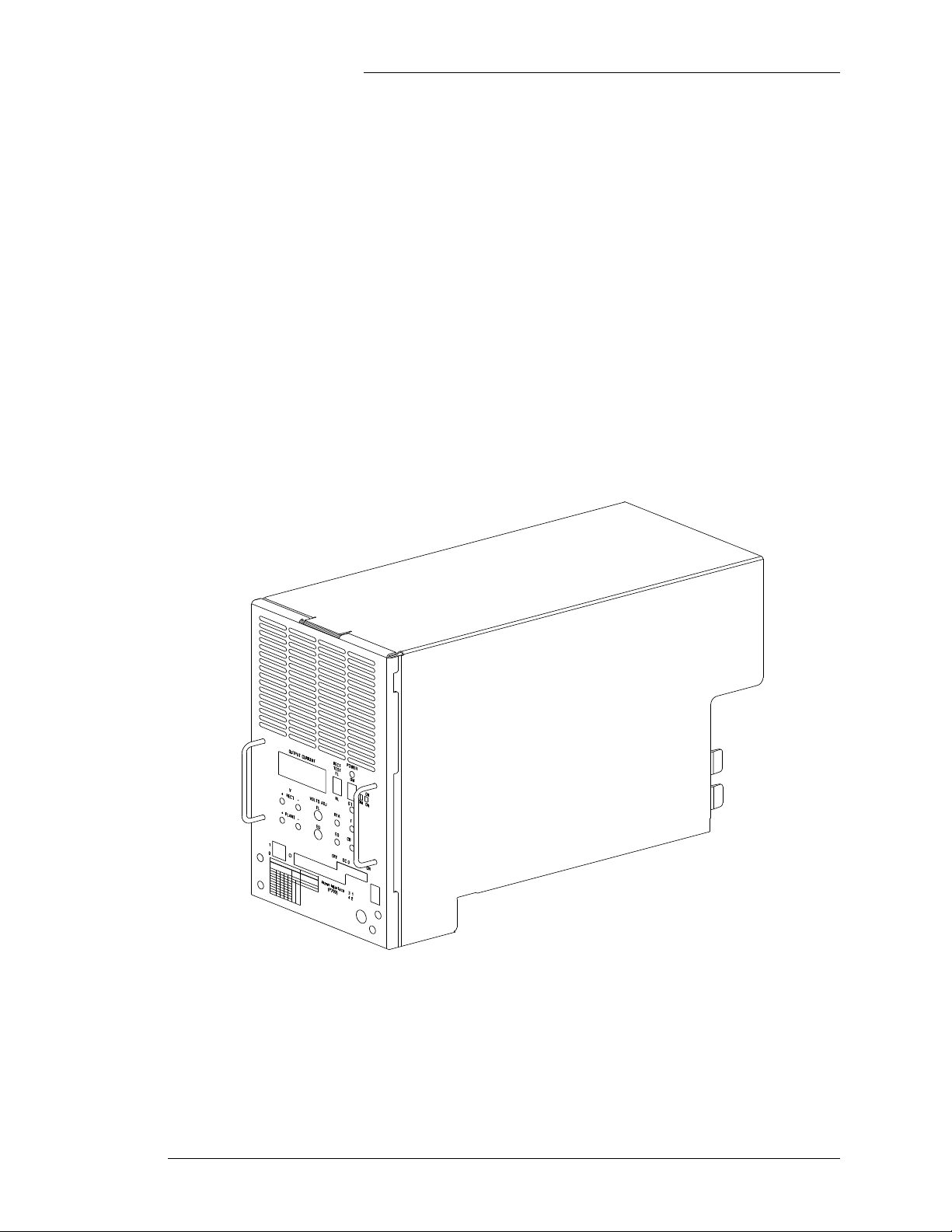
Information This product manual describes Lucent Technologies’ Lineage®
2000 364A3 50-ampere,-48-volt SR series rectifier (Figure 1-1)
and the associated rectifier shelf assemblies, J85702B-2 and
J85702F-1 (Figure 1-2). The 364A3 rectifier replaces all
364A-type rectifiers described in previous issues of this product
manual. These rectifiers are backward and forward compatible
and may be interchanged at will in any system. Although the
apparatus codes and comcodes are different, the ordering
procedures are identical for all -48-volt SR series rectifiers.
Lucent Technologies has designed the 364A3 rectifier
specifically for applications where small size, low weight, and
ease of installationand maintenance are critical. UL recognized,
the 364A3 rectifier can be operated with or without batteries,
providing maximum applications flexibility. The rectifier is
plugged into the Rectifier Shelf Assembly (RSA) and all
interconnections between the controller, rectifier, and
distribution are completed.
A complete technical description of the product is coveredin this
manual as well as detailed information on engineering,
installation, operation, and maintenance.
Technical
Support Technical support for Lucent Technologies equipment is
available to customers around the world.
USA, Canada,
Puerto Rico, and
the US Virgin
Islands
Onapost-sale basis,duringtheProductWarrantyperiod,our
Technical Support telephone number 1-800-CAL RTAC
(1-800-225-7822) provides coverage during normal business
hours. Product Specialists are available to answer your technical

Lucent Technologies Lineage®2000 50A -48V 364A-3 SR Series Rectifier
1 - 2 Introduction Issue 6 January 1997
questions and assist in troubleshooting problems. For
out-of-hours EMERGENCIES, the 800 number will put you in
touch with a Regional Technical Assistance Center Engineer via
our 24 hour a day, 7 day per week Help Desk.
When Technical Support is required in the Post-Warranty
Period, the service may be billable unless you hold an extended
warranty or contractual agreement.
Central and
South America If you need product technical support, contact your local Field
Support/Regional Technical Assistance Center or contact your
sales representative who will be happy to discuss your specific
needs.
Europe, Middle
East, and Africa If you need product technical support, contact your local Field
Support/Regional Technical Assistance Center or contact your
sales representative who will be happy to discuss your specific
needs
Asia Pacific
Region If you need product technical support, contact your local Field
Support/Regional Technical Assistance Center or contact your
sales representative who will be happy to discuss your specific
needs.
Product Repair
and Return Repair and return service for Lucent Technologies equipment is
available to customers around the world.
USA, Canada,
Puerto Rico, and
the US Virgin
Islands
For information on returning of products for repair, customers
may call 1-800-255-1402 for assistance.
Central and
South America If you need to return a product for repair, your sales
representative will be happy to discuss your individual situation.
Europe, Middle
East, and Africa If you need to return a product for repair, your sales
representative will be happy to discuss your individual situation.

Lucent Technologies Lineage®2000 50A -48V 364A-3 SR Series Rectifier
Issue 6 January 1997 Introduction 1 - 3
Asia Pacific
Region If you need to return a product for repair, your sales
representative will be happy to discuss your individual situation.
Customer
Service For customer service, any other product or service information,
or for additional copies of this manual or other Lucent
Technologies documents, call 1-800-THE-1PWR
(1-800-843-1797). Specify the select code number for manuals,
or drawing number for drawings. These numbersare listedin the
following reference table.
Contact your regional customer service organization or sales
representative for information regarding spare parts.
Figure 1-1: Lineage®2000 SR 50A/-48V 364A3 SR Series
Rectifier
SR50/–48V

Lucent Technologies Lineage®2000 50A -48V 364A-3 SR Series Rectifier
1 - 4 Introduction Issue 6 January 1997
Figure 1-2: 364A3 Rectifiers in Rectifier Shelf Assembly
Lucent
Lucent
Lucent

Lucent Technologies Lineage®2000 50A -48V 364A-3 SR Series Rectifier
Issue 6 January 1997 Product Description 2 - 1
2 Product Description
Electrical
Specifications Table 2-A: 364A3 Electrical Specifications
Nominal Output
Voltage -48 volts dc
Operating Voltage
Range 48-58 volts dc
Output Current 0-50 amperes
Input Voltage 208/220/240 volts ac, single phase
Input Voltage Range 180-264 volts ac
Input Frequency Range 47-63 Hz
Input Current 16.5 amperes @ 208 volts ac
14 amperes @ 240 volts ac
Efficiency 86% typical
Power Factor 0.99 typical
Regulation +0.5%
AC Ripple 250 millivolts peak to peak
Output Noise 22 dBrnc with battery
26 dBrnc without battery
Load Share Accuracy 10 amperes
Heat Dissipation 1540 BTU/hour
Temperature 32° F to 122° F (0° C to 50° C)

Lucent Technologies Lineage®2000 50A -48V 364A-3 SR Series Rectifier
2 - 2 Product Description Issue 6 January 1997
Notes:
1. Data specified for nominal input voltages and frequencies
and rate outputs of 55.5 volts and 50 amperes.
2. Data describing regulation, ac ripple, and output noise are
specified at the terminals of a 200 ampere-hour battery
(8-hour rate) with the rectifier operating as specified above
and with the Bellcore-specified 1-volt lead drop between
the rectifier and the battery terminals.
3. For altitudes of 5000 to 13000 feet, derate maximum
temperature by 3.6° F per 1000 feet above 5000 feet. For
altitudes of 1524 to 3962 meters, derate maximum
temperature by 0.656° C per 100 meters above 1524
meters.
Altitude -200 to 13,000 feet (-61 to 3962
meters) (See Note 3.)
Humidity 10 - 95% non-condensing
Audible Noise 57 dBA measured from 2 feet (0.6
meters) from the rectifier
Electrostatic Discharge IEC 801-2 Level 5
Radiated and Conducted
Emissions FCC Level A, CISPR Level A
Electromagnetic
Immunity 10V/m over the range of 20 to
2000 mHz
Earthquake Rating Zone 4, upper floors
Safety Agency
Approvals UL 1950
Table 2-A: 364A3 Electrical Specifications

Lucent Technologies Lineage®2000 50A -48V 364A-3 SR Series Rectifier
Issue 6 January 1997 Product Description 2 - 3
Physical
Specifications Table 2-B: 364A3 Physical Specifications
Rectifier
Height 11.6 inches (295 millimeters)
Width 7.00 inches (178 millimeters)
Depth 15.25 inches (387 millimeters)
Weight 25 pounds (11.3 kilograms)
Rectifier Shelf Assembly (J85702B-2/J85702F-1*)
Height (Lists 2, 3, 5) 4.80 inches (122 millimeters)
Height (List 4) 4.91 inches (125 millimeters)
Height* (J85702F-1) 4.97 inches (126 millimeters)
Width 21.5 inches (546 millimeters)
Depth (Lists 2, 3, 5) 15.68 inches (398 millimeters)
Depth (List 4) 17.41 inches (442 millimeters)
Depth* (J85702F-1) 17.11 inches (435 millimeters)
Weight 25 pounds (11.3 kilograms)
Rectifier Shelf Assembly Equipped With Three Rectifiers
Height 12 inches (305 millimeters)
Weight 100 pounds (45.2 kilograms)
Frame Mounting Requirements
Relay Rack Standard 23 or 26 inch
Vertical Mounting
Centers 1 inch (25 millimeter)
Horizontal Mounting
Centers 22.32 inches (567 millimeters) or
24.32 inches (618 millimeters)

Lucent Technologies Lineage®2000 50A -48V 364A-3 SR Series Rectifier
2 - 4 Product Description Issue 6 January 1997
SR Series
Rectifier
Technology
The Lucent Technologies family of SR series rectifiers
represents a significant advancement in spaceutilization, easeof
installation, and weight reduction over previously available
products.
The Lineage®2000 364A3 50-ampere, -48-volt SR series
rectifier uses switchmode technology to convert commercial
50/60 Hz ac input power into highly regulated and filtered,
low-noise, -48-volt dc output power for telecommunications
equipment loads. Since telecommunication systems typically
obtaintheirprimary powerfrom potentiallynoisy commercialac
lines (and emergency alternators during commercial power
failures) and since high-quality dc power is required in order for
the equipment to function correctly, the 364A3 rectifier is an
excellent choice for a telecommunications power plant. The
rectifier provides excellent output regulation over a wide range
of load currents, input voltages, and input frequencies.
Processing thepowerathigherfrequencies allows for substantial
reduction in the size and weight of the energy storage elements.
Benefits Improved Space Efficiency: A unique Lucent Technologies
Bell Laboratories design, which incorporates 70 kHz switching
frequency,has resulted in rectifierswhichoccupy approximately
one-third of the space and weigh one-seventh as much as
comparable ferroresonant rectifiers. The 364A3 rectifier plugs
into a shelf assembly that can house three rectifiers. In addition,
several rectifiers can be configured in parallel arrangements to
provide capacities up to 600 amperes in 48 inches of vertical
space.
Reduced Installation and Maintenance: Its unique plug-in
design, front access capability, and light weight make the 364A3
rectifier easy to install and simple to maintain.
Continuous Operation:364A3 rectifiers can easily be added to
Lineage®2000 battery plants without interrupting power to the
load.
Increased Cost Effectiveness: Space efficiency, ease of
installation and maintenance, high reliability, and a near unity
power factor result in lower operating costs. The 364A3
rectifier’s modular design allows your plant to begin small and
to grow as required.

Lucent Technologies Lineage®2000 50A -48V 364A-3 SR Series Rectifier
Issue 6 January 1997 Product Description 2 - 5
High Reliability: The 364A3 rectifier’s forced convection
design improves the mean time between failure of its
components by a factor of two, thus ensuring high reliability.
Power Factor Correction Circuit: The SR series rectifiers
contain a power factor correction circuit that ensures power
factor above 0.98 for all loads above 50 amperes.Thisallows for
an input current waveshape with low harmonic distortion,
ensuring compatibility with engine alternators and UPS. The
power factor correction circuit also allows operation over a
much wider input voltage range than ferroresonant or silicon
controlled rectifier (SCR) technologies, eliminating the need for
tap changes in the rectifier.
Forced-Air Cooling: The SR series rectifiers use forced-air
cooling to help achieve high power density and light weight.
Each unit is equipped with an easily replaceable, self-contained
cooling fan. (See Section 7, Maintenance.) Thermal alarm
circuitry offers additional protection by shutting the rectifier
down and providing an alarm when the internal temperature
exceeds approximately 60° C. Forced air cooling improves the
reliability of the rectifier by reducing the internal ambient
temperatures of the rectifier to essentially the outside ambient
temperature. This allows Lucent Technologies to offer a
switchmode product that meets the same high reliability
standards as our ferroresonant rectifiers.
Self-Protection:Short circuits and overloads are handled safely
and automatically. Various monitoring and alarm signals are
generated by the rectifiers and sent to the ECS controller (if
present) for processing and further action. The resulting action
may be local or remote alarm indications or control signals fed
backtothe rectifier.(Refer to the Lineage®2000 ECSController
Product Manual for a description of rectifier signal processing
and resultant action.) See Figure 3-1 for typical signal flow
between a rectifier and the ECS controller.
Batteries and Load: In most telecommunications applications,
the output of the rectifiers is electrically connected in parallel
with the batteries and the load. Under normal conditions the
rectifiers power the load and provide the float and charging
current required by the batteries. During a commercial ac power
outage, the batteries supply the dc power to the load. When ac
poweris restored,the rectifiers recharge the batteries and supply
dc power to the load. No switching is needed in this transition
because of the parallel connection of the rectifiers and batteries.

Lucent Technologies Lineage®2000 50A -48V 364A-3 SR Series Rectifier
2 - 6 Product Description Issue 6 January 1997
Although the rectifiers are typically used in a battery plant, these
rectifiers can operatewithoutbatteries, making them suitable for
those applications where battery back-up is not necessary or is
achieved using an uninterruptible power supply (UPS).
Features The following list describes the standard features designed into
the 364A3 rectifier.
Load Share: A DIP switch selectable option enables the
rectifier to share the plant load automatically with other SR
series rectifiers. The load share circuit is fail-safe, using an
isolated load share bus between the rectifiers. Upon failure, the
failed rectifier is disconnected from the load share bus.
Equalize: The rectifier, in conjunction with the ECS controller,
can charge batteries at higher voltages than the float voltage. A
separate potentiometer allows the equalize voltage to be set
independently of the float voltage. A front-panel LED indicates
when the rectifier is in equalize mode.
Parallel Operation: The rectifiers are capable of parallel
operation.
Safety Interlock: A mechanical interlock between the rectifier
and the RSA prevents the rectifier from being installed in the
RSA with the circuit breaker closed. On installation, the
interlock and associated circuits limit surges of current into the
rectifier output capacitors when the rectifiers are initially
connected to the battery bus.
Output Current "Walk-in": This circuit controls the time
required for the rectifier to reach full output current after it is
turned on. Initially, the output current is zero and is gradually
increased to the required output current in about 10 seconds at
full load. This feature minimizes the starting surge on the
customer's power source, which is especially useful when the
source is finite, such as with an engine alternator set.
Note
CB OFF must be lit and the DC OUTPUT breaker in the OFF
position to adjust the output of the rectifiers correctly in load
share mode.

Lucent Technologies Lineage®2000 50A -48V 364A-3 SR Series Rectifier
Issue 6 January 1997 Product Description 2 - 7
External Selective High-voltage Shutdown: If the plant
voltageis toohigh,theLineage®2000 ECScontrollerwill signal
all of the operating rectifiers that a high voltage is present. The
rectifier(s) causing the overvoltage will shut down. The
remaining rectifiers will continue operation.
Internal Selective High-voltage Shutdown: If the rectifier
voltage is too high (based on a user-selectable level), and the
rectifier is delivering at least 10% of its rated output current, the
rectifier will shut down. When rectifiers are operating in load
share mode and a high-voltage situation occurs, only the
defective rectifier will shut down. If the rectifier is connected to
a Lineage®2000 ECS controller, the internal high-voltage
shutdown will automatically be disabled and the controller will
furnish the selective high voltage shutdown signal. The
high-voltage shutdown level can be set in increments of 1.0 +0.5
volts between 50 and 58 volts by a DIP switch on the front of the
rectifier.
BackupHigh-voltageShutdown:This circuitprevents damage
to the rectifier and its loads in the event of a high-voltage
condition. The rectifier monitors its output voltage and shuts
down when this voltage exceeds a user-selected threshold
programmed by DIP switches in the rectifier.
OutputCurrentLimit: The rectifier provides a constant output
voltage up to its rated output current, at which point it provides
constant current. The output current is limited to less than 110%
of the rated output and no user adjustment is necessary.
Rectifier Test: A front panel switch is provided for
automatically raising or lowering the output voltage of the
rectifiers a small amount in order to test operation.
Lamp Test: This circuit allows the front panel display and
LEDs to be tested. When the unit is in STBY and the NL/FL
switch is pressed in either direction, all of the front panel LEDs
and meter segments will activate.
Restart Circuit: The rectifiers are compatible with the
automatic restart features of the Lineage®2000 ECS controller.
If a rectifier has been shut down due to high voltage, the plant
will try once to restart it automatically.

Lucent Technologies Lineage®2000 50A -48V 364A-3 SR Series Rectifier
2 - 8 Product Description Issue 6 January 1997
Metering: A 3-1/2 digit, back lit, LCD meter indicates the
output current of the rectifier with an accuracy of +0.9% of full
scale +1 count.
ActiveInrushCurrentLimiting:Upon initial application of ac
source voltage, an active circuit limits the peak inrush current.
This prevents possible tripping of input breakers or overloading
of engine alternators during ac source voltage transfers.
Initial ChargeMode:The rectifiers arecapableof providing 60
volts (at somewhat less than rated current) to charge batteries
initially during plant installations.
Rectifier Failure Alarm (RFA): An RFA alarm provides both
a local visual indication of failure and a signal to the plant
controller. An RFA is generated by the following:
1. high voltage shutdown
2. thermal alarm
3. rectifier fuse alarm or circuit breaker overcurrent
operation
AC Fail Alarm: An ac input voltage of less than approximately
170 vrms causes an alarm to be issued to the controller. An ACF
alarm is also transmitted to the controller if the ac input fuses
located inside the rectifier have operated. Fuses should not be
replaced in the field.
Transfer (TR): The rectifiermay be placed in the standby mode
byan externally generatedsignal. Therectifierwillremain inthe
standby mode until removal of that signal.
Thermal Alarm (TA): The SR series rectifiers are fan cooled to
increase their reliability. High temperatures caused by fan
failure or other conditions cause the rectifier to shut down and a
thermal alarm to be issued. See Section 7, Maintenance, for
details on fan replacement.
DC Output Breaker: A circuit breaker is provided to protect
the rectifier from malfunction and overcurrent. It may also be
used to disconnect the rectifier from the battery.
Remote Sense: The rectifier can regulate remotely and can
compensate for a voltage drop of up to 2 volts between the
rectifier's output terminals and the regulation point.

Lucent Technologies Lineage®2000 50A -48V 364A-3 SR Series Rectifier
Issue 6 January 1997 Product Description 2 - 9
Test Jacks: Two sets of test jacks are provided. One set
measures the plant voltage at the remote regulation sense point.
The other set measures the voltage internal to the rectifier before
the dc output circuit breaker. When the breaker is open and the
rectifier is on but disconnected from the local bus, the rectifier
output voltage can be adjusted without affecting the plant
voltage.
Wide ac Input Frequency Range: The rectifier’s power factor
correction circuit and switchmodetechnology allow itto operate
over 47 to 63 Hz with no degradation in performance.
Lightning and Switching Surge Protection: The rectifiers are
capable of withstanding, without damage, repeated surges of the
following waveforms (as defined in the referenced tables in
IEEE C62.41 - 1991):
Operation Without Batteries: The Lineage®2000 SR series
rectifier is capable of working without batteries without
affecting performance.
Table 2-C: Lightning and Switching Surge Protection
Wave Form C62.41 Reference
100 KHz Ring Wave Table 3 (Category B3)
8/20µS Pulse Table 4 (Category 3B)
10/1000µS Pulse*
(*this feature only on
364A2 series 1:2 and higher
and 364A series 2:2 and
higher rectifiers)
Table 8 (High Exposure)
Note
A metal oxide varistor (MOV) type service entrance protector
is recommended. (See IEEE C62.41-1991 Figure B10.)
Service entrance protection should be coordinated with the
MOV rating of the MOV in the rectifier. All rectifiers 364A
series 1:1 and 364A series 2:2 and lower have 275 vrms
MOVs. All other 364A-type rectifiers (including 364A3) have
320 vrms MOVs. Additional information on Total Surge
Management is available in application note 94ESDEV044
(available from Power Systems Document Control Center.)
This manual suits for next models
1
Table of contents
Other Lucent Technologies Industrial Equipment manuals
Popular Industrial Equipment manuals by other brands

Wilo
Wilo Wilo-Flumen OPTI-TR 28-1 Installation and operating instructions

6K Products
6K Products DH0602 Operation and parts manual

RelaDyne
RelaDyne ThermoJet G5700 Series Installation and operating manual

Jäger
Jäger ZS62-D360.53 S2A manual

HBK
HBK PMX operating manual

Elkay
Elkay LK4461YHLHB Series owner's manual