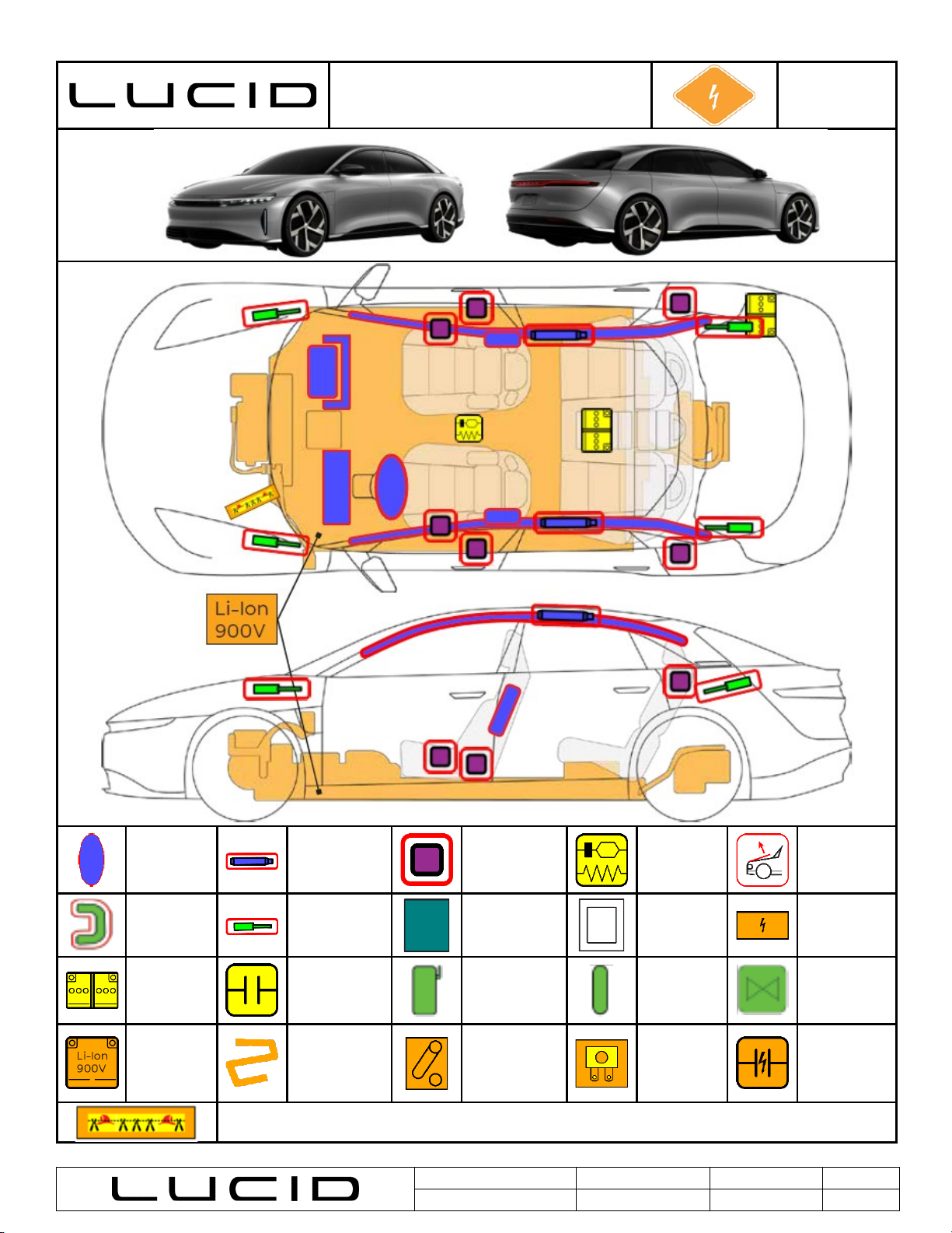
Even if the first responder loop has been cut, always treat the high-voltage pack and the high-voltage components as if they are live.
The pack will still have stored energy within the cells, and it is not known if other high-voltage components have been damaged.
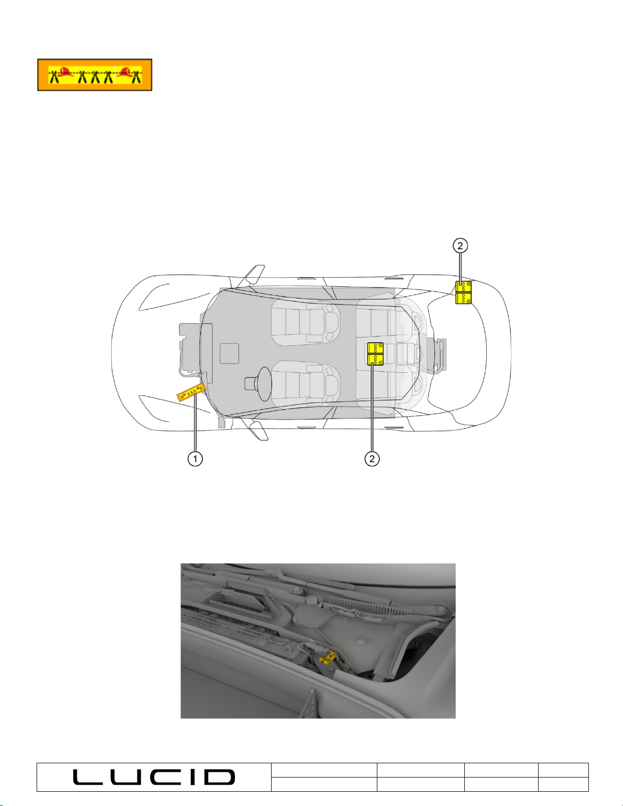
Treat every battery pack and orange cable as if there is high voltage in them. Never cut an orange high-voltage cable or cut into the
battery pack.
There is no way to instantaneously discharge the energy inside of the battery pack when a vehicle is in an accident. There is stored
energy in the high-voltage battery cells. Caution must be used to not damage the battery pack, in the case of vehicle extrication
operations.
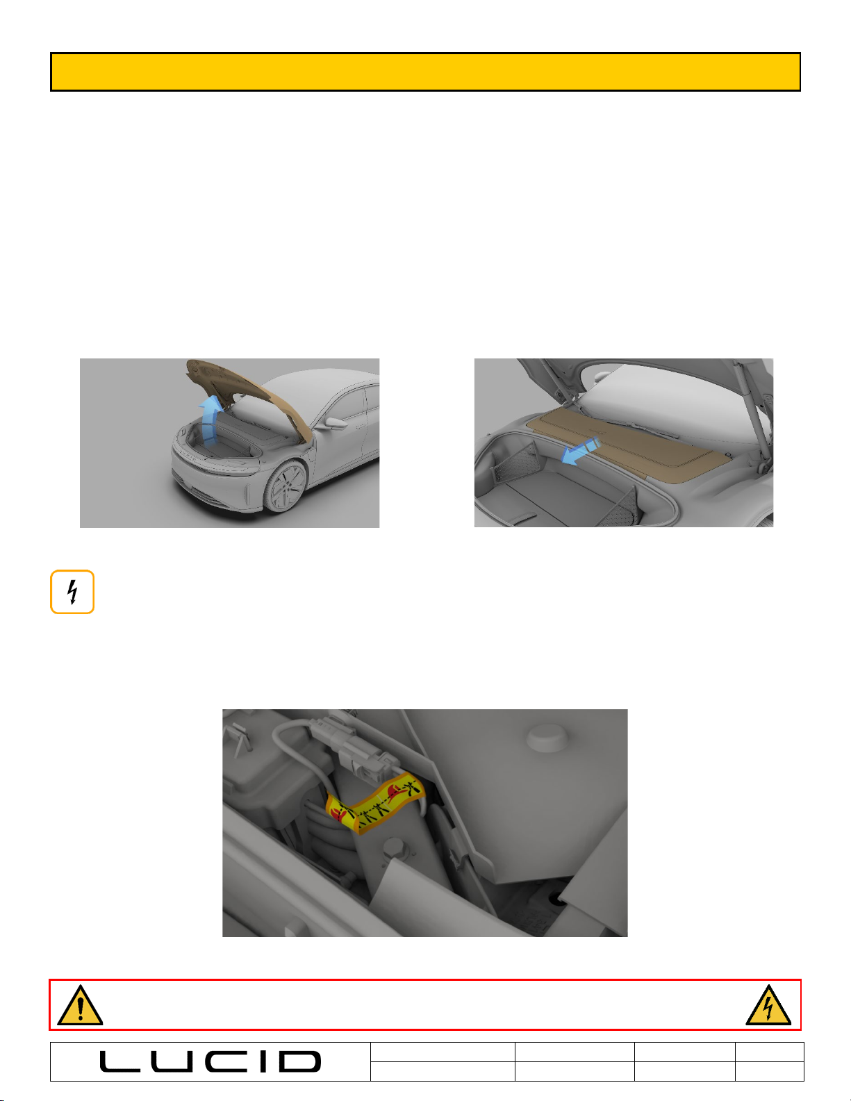
Vehicle Charging
In the case of an emergency incident while charging that involves collision, electrical failure, or fire, additional steps should be taken
to isolate the charging station. If the charging station is equipped with an e-stop, it should be applied. If an e-stop is not present or
accessible, property management should be accessed to locate the main service disconnect and lockout/tagout breaker. After it has
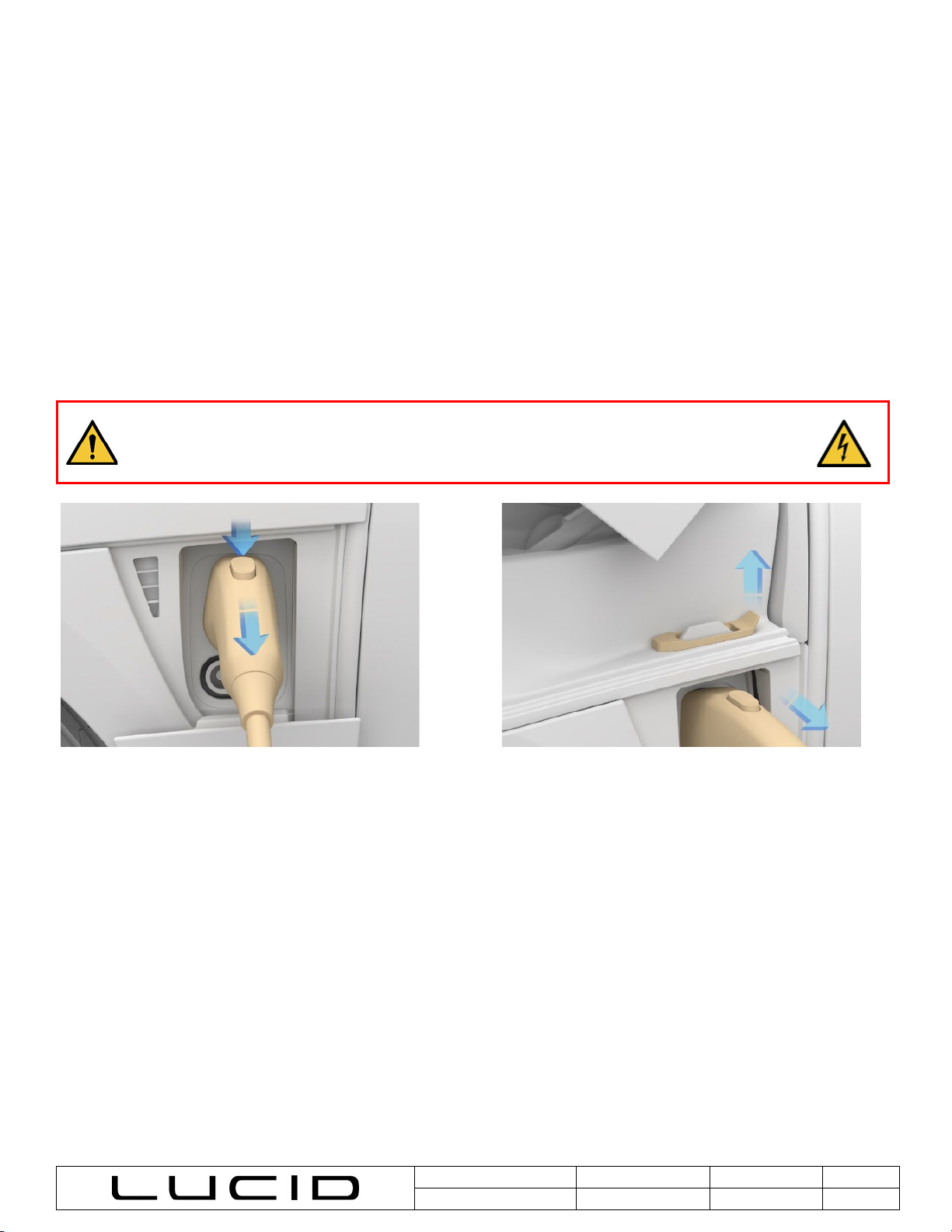
been located, immediately disconnect the EVSE handle at the vehicle by pressing the release button on the charging cable handle. If
you are unable to disconnect via the handle button, the manual release can be actuated by opening the hood and pulling the manual
release lever while unplugging the cable.
WARNING Do not cut the high-voltage charging cable. If the Electric Vehicle Supply Equipment (EVSE) is
unable to be disconnected from the vehicle, ensure that the EVSE is de-energized before proceeding. Refer
to the EVSE manufacturer’s instructions or Local Power Utility Agency. Cutting an energized cable may lead
to serious injury or death.
Disconnecting EVSE cable via handle button
Manual release lever operation