LUDOMIDE Y1095-WH Product guide

Model No.: Y1095-WH / Y1095-BK
Ceiling Fan with Lights
APP Control Applicable
Scan for Installation Video

Please contact us with following information:
1. Screen shot of your order page, including product picture, name and order
ID number.
2. Problem details with pictures / short video if possbile.
Email: [email protected]
1
Contact Information

Packing List
A
B
C
D
E
Part
A
B
C
Note: Some parts may be assembled together in the package.
2
Description
Bracket
Canopy
Fan Assembly
Quantity
1
1
1
Part
D
E
Description
Remote Control
Remote Holder
Quantity
1
1

Installation kit
Part
AA
BB
CC
DD
EE
FF
Description
Canopy Screw (assembled)
Wire nut
Pair of Gloves
“S” Hook
Wood Screw (opitional)
Machine Screw & Washer for Outlet Box (spares)
Quantity
4
3
1
1
4
2
AA BB CC
DD EE FF
Note:
Some extra hardware may be included. The quantity listed above is the number
required for installation.
3

1. Be sure the power to the wires you are working on is disconnected, either the fuse
is removed or the circuit breaker is turned off. Turning the power off using the light switch
is not sufficient to prevent electrical shock.
2. A qualified licensed electrician is required for the installation.
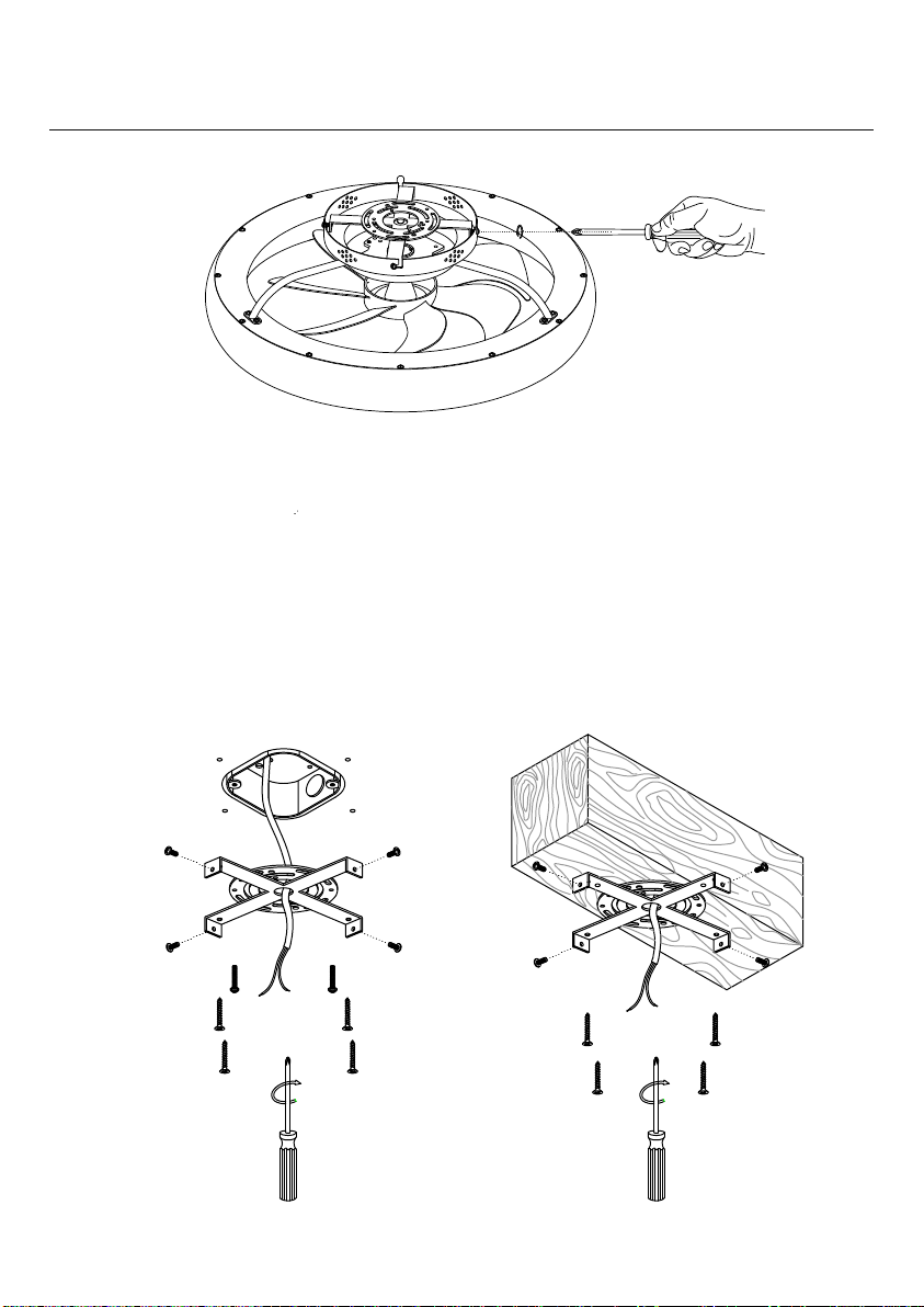
3. The outlet box and support structure must be securely mounted and capable of reli-
ably /supporting a minimum of 50 pounds. Use only UL (cUL for Canadian Installation)
listed mounting boxes marked "FOR FAN SUPPORT".
4. The fan must be mounted with a minimum of 7 feet clearance from the trailing edge of
the blades to the floor.
5. Do not operate reversing switch while fan blades are in motion (if applicable). Fan must
be turned off and blades stopped before reversing blade direction.
6. Do not place any objects in the path of the blades.
7. To avoid personal injury or damage to the fan and other items, be cautious when work-
ing around or cleaning the fan.
8. Do not use water or detergents when cleaning the fan or fan blades. A dry dust cloth or
lightly dampened soft cloth will be suitable for the cleaning.
9. After marking electrical connections, spliced conductors should be turned upward and
pushed carefully up into outlet box. The wires should be spread apart with the grounded
conductor on one side of the outlet box.
10. Electrical diagrams are reference only, different fan light may have different light shade
and bulbs.
11. Use only our replacement parts. This equipment has been tested and found to
comply with the limits for a class B digital device, pursuant to part 15 of the FCC Rules.
These limits are to provide reasonable protection against harmful interference in a resi-
dential installation. This equipment generates, uses and can radiate radio frequency en-
ergy and if not installed and used in accordance with the instructions may cause harmful
interference to radio communications.
Warning:
To reduce the risk of personal injury, use only the two steel screws and washers provided
with the outlet box for mounting to the outlet box. Most outlet boxes commonly used for
the support of lighting fixtures are not acceptable for fan support and need to be replaced,
consult a qualified electrician if in doubt.
To reduce the risk of fire, electric shock or person injury, mount fan to outlet box marked
"acceptable for fan support".
To reduce the risk of personal injury, do not bend the blade brackets (also referred to
as flanges) during assembly or after installation. Do not insert objects in the path of the
blades.
Safety Rules
4

What to Expect with Your Installation
Tools You Need
Must be able to
secure the fan
to building
structure or fan-
rated outlet box
30 inches
from blade
tip to nearest wall or
obstruction
You may need a
friend to help you.
Assess location
If mounting to a support structure, you will also need the optional tools.
Ladder Pliers Screwdrivers
Wire
Strippers Power Drill
(optional) Drill Bit
(optional)
7 feet from bottom edge
of blade to the floor
Check box to see
fan weight
Angled Ceilings are
not supported.
Angled Ceiling
not supported
X
Installation Preparation
5

the bolt
(Fig. 6).
Step 5. Fix the downrod with set screws provided.
3. Hanging the Fan
Place the downrod ball into the bracket socket
(Fig. 7). Be sure the fixation slot is locked by the
bracket.
Installation Step 1 (Mount the Bracket)
Loosen screws from the canopy (don't take off), take out the bracket from the
canopy.
With Outlet Box: Fix the bracket onto the outlet box with screws from the outlet
box, fix the cross bar of the bracket onto to the ceiling with 4 wood screws (op-
tional).
Without Outlet Box: Fix the cross bar onto the solid wood structure with 4
wood screws.
Outlet Box
Bracket
Machine Screw
(from outlet box)
Solid Wood Structure
Bracket
Wood Screw
Option 1 Option 2
OR
6
Wood Screw
(optional)

Installation Step 2 (Connect the Wires)
2. Connect wires from the fixture to the wires from outlet box with wire nuts,
ground wire (green, green/yellow or bare copper) to ground wire, neutral wire
(white or blue) to the neutral wire, hot wire (black or brown) to the hot wire.
Wrap the connection with electrical tape.
3. Take away the "S" hook.
7
Bracket "S" Hook
Canopy Slot
1. Hang the fixture onto the bracket with "S" hook provided.

Installation Step 3 (Fix the Canopy)
1. Fix the bracket screws onto the bracket but not tighten them.
2. Align the "L" slots from the canopy to the screws on the bracket, rotate the
canopy to lock it onto the bracket.
3. Tighten the screws.
8
Installation Step 4 (Install the Remote Holder)
1. Insert 2 batteries before
using:
AAA 1.5V battery x 2pcs
(not included)
2. Install the remote holder
onto the wall with screws.

NOTE:
Please insert 2 batteries before using.
AAA 1.5V battery x 2pcs (not included)
①Turn on/off the light.
②④ Adjust the brightness of the light.
③⑫Adjust the light color temperature.
⑤Stop the fan.
⑥Night mode, lights will be dimmed when press this button.
⑦1-6 fan speed.
⑧⑭Timing the fan
⑨Fan moves forwards or reversely.
⑩Turn off fan including the light.
⑪Quick switch of the light color: Yellow Light→White Light→Natural Light
⑬Natural wind of the fan, fan speed will change automatically.
Remote signal pairing:
If the remote control looses signal of the fan, press and hold ⑪button at the very
beginning after it's turned on from wall switch. After the light flashes, it's done.
①
②
③
④
⑤
⑥
⑦
⑧
⑨
⑩
⑪
⑫
⑬
⑭
Remote Control Instructions
9

NOTE: Scan the QR code and install the APP in
your phone, or search and install "FanLamp
Pro"from Google Play, Apple App and other
APP stores.
Make sure your phone is connected to the in-
ternet and bluetooth enabled.
Pair button. Click it within 5 seconds after the
fan is powered on from wall switch. After the fan
flashes or beeps, it has been successfully paired
with the phone, it can be controlled through it.
Slide to change the fan speed.
Slide to change the brightness of the light.
Quick switch for "White" light color.
Quick switch for "Yellow" light color.
Quick switch for "Natural" light color.
Night mode, dim the lights.
Fan moves forwards.
Change the direction of the wind (Not applicable
on this fan).
Timing the fan.
Natural wind: fan speed will change automati-
cally when use this function.
Sleeping wind (Not applicable on this fan).
Fan moves reversely.
Turn on/off the light.
Turn on/off the fan.
Unpair button. Click it within 5 seconds after the
fan is powered on. After the fan flashes or beeps,
it has been successfully unpaired with the phone.
APP Control Instructions
10

1. Fan doesn't work
• Make sure the fixture is connected to an ON/OFF wall switch, not dimmer switch.
• Check the remote control battery (not included in this package).
• Check the circuit breaker to ensure the power is on.
• Turn off power from the circuit breaker, then loosen the canopy and check all the con-
nections according to the wiring diagram.
2. Lights Do Not Light Up / Flicker / Noisy Operation
• Make sure the fixture is connected to an ON/OFF wall switch, not dimmer switch.
• Check your power and switch to make sure it's power on.
3. Noisy Operation
• Re-tighten all screws on bracket.
• Check to see if any of the blades are cracked. If so, replace the blades.
4. Remote does not work
• Make sure the battery is installed correctly.
• Pair the remote control again (See page 9).
• Install 2 new batteries.
Trouble Shooting
Clean And Care
To clean, wipe the fixture with soft cloth. Spray from chemical cleaners can discolor the
finish of the fixture. Do not use scouring pads, powders, steel wool or abrasive paper to
clean this fixture.
Ordering Parts
Keep this manual for future reference, and in case replacement parts are needed.
Available parts can be ordered from place of purchase. Use exact wording from diagrams
when ordering parts.
11
This manual suits for next models
1
Table of contents