OTT HydroMet Fellbach GmbH, Gutenbergstr. 20, 70736 Fellbach, Germany
Kurzanleitung ANACON Rev 3, 07/2021
48.4604-610
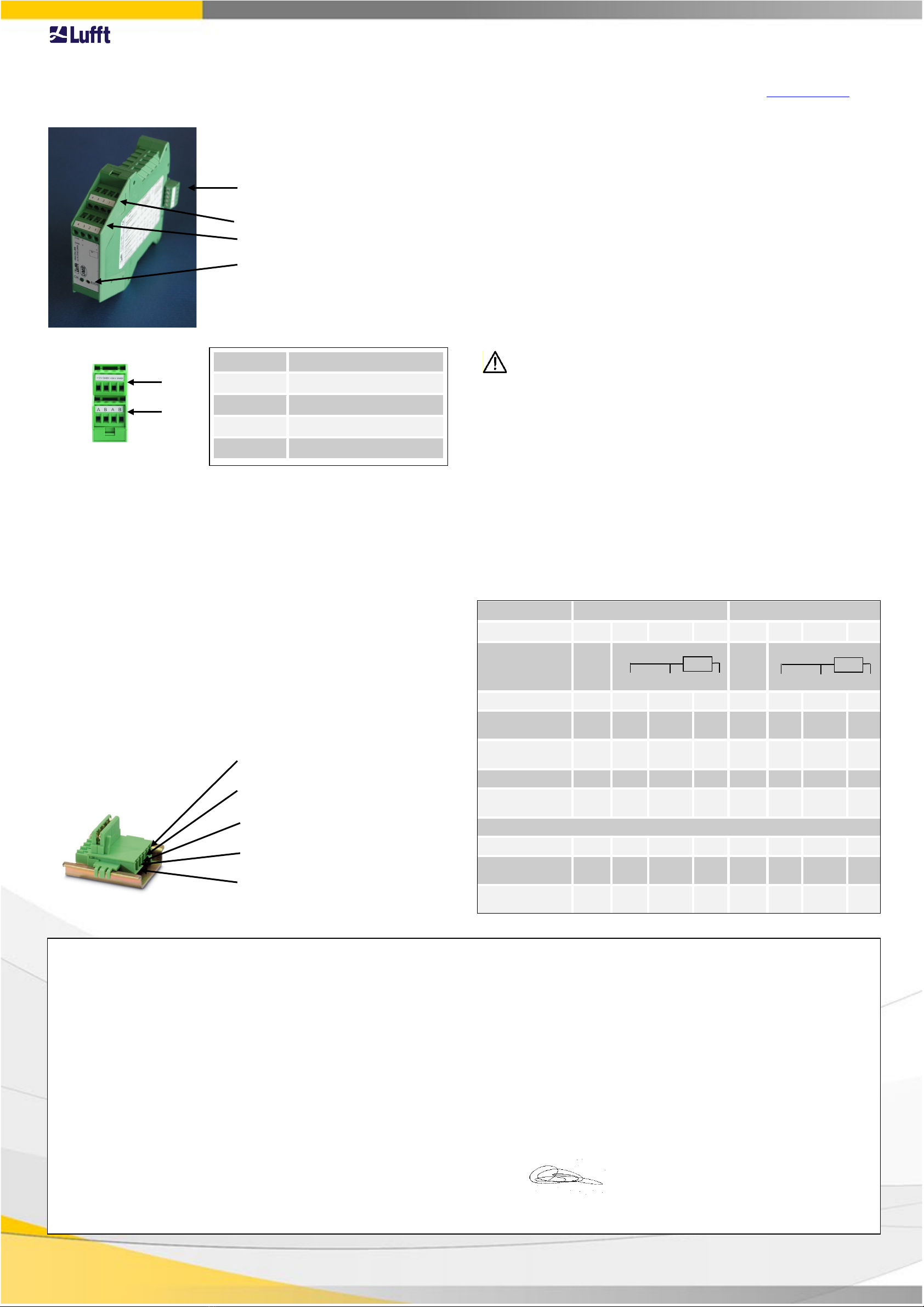
Übersicht
Montage und Inbetriebnahme
1. Konfigurieren Sie zuerst alle Module mit der Konfigurationssoftware UMB-
ConfigTool.net entsprechend Ihren Vorgaben (s. Kapitel Konfiguration).
2. Setzen Sie die benötige Anzahl an Tragschienen-Busverbindern auf die
Hutschiene und rasten Sie anschließend alle ANACON-Module auf.
3. Schließen Sie die Sensoren an die Kanäle A und B des ANACON-Moduls an.
Beachten Sie, dass bei den Kombisensoren für Windgeschwindigkeits- und
Windrichtungssensoren eine feste Belegung der Kanäle A und B vorgegeben ist.
Eine Übersicht über das Anschlussschema der Sensoren finden Sie in der
nachfolgenden Tabelle.
4. Schließen Sie jetzt an den Tragschienen-Busverbinder die 24V-Versorgung an.
5. Verbinden Sie Ihr Host-System mit einer beliebigen RS232-Schnittstelle eines
ISOCON. Die Anlage ist jetzt betriebsbereit.
Tragschienen-Busverbinder, Montage muss auf einer geerdeten Hutschiene erfolgen!
Die ausführliche Betriebsanleitung finden Sie unter: www.lufft.com.
Konfiguration
Die ANACON-Module werden werksseitig alle mit der ID 1 ausgeliefert. Werden in einem
UMB-Netzwerk mehrere Module eingesetzt muss sichergestellt werden, dass alle Module
des Netzwerks eine unterschiedliche ID besitzen. Folgende Schritte für die Konfiguration
sind zu beachten.
1. Setzen Sie einen Tragschienen-Busverbinder auf die Hutschiene und schließen
Sie die 24V mittels des mitgelieferten Steckers an. Achten Sie bitte auf die
korrekte Polung und die Pin-Belegung beim Anschluss. Ein falsches Anschließen
kann das ANACON-Modul zerstören!
2. Rasten Sie anschließend das ANACON-Modul auf, das Sie konfigurieren
möchten.
3. Für die Verbindung mit der RS232 Schnittstelle des PCs ist ein ISOCON
(8160.UISO) notwendig. Clipsen Sie den ISOCON ebenfalls auf die Tragschiene
auf und verbinden das Modul über die RS232-Schnittstelle mit Ihrem PC.
4. Stellen Sie mittels dem UMB-ConfigTool.net die gewünschte ID und die
Kanalkonfiguration ein. Auf der Vorderseite des Moduls können Sie in dem
Beschriftungsfeld die konfigurierte ID eintragen.
Das ANACON ist jetzt betriebsbereit und kann von der Hutschiene gelöst werden.
Wiederholen Sie bitte für alle weiteren ANACON-Module die Schritte 2 bis 5.
Statische Aufladungen können elektronische Geräte beschädigen. Entladen Sie
die elektrische Aufladung Ihres Körpers vor dem Öffnen und Konfigurieren des
Gerätes: Berühren Sie dazu eine geerdete Oberfläche, z.B. das Metallgehäuse des
Schaltschrankes.
Status-LEDs
Um die korrekte Konfiguration und Funktion des ANACONs anzuzeigen, befinden sich 2
LEDs an der Vorderseite des Gerätes. Diese haben folgende Bedeutung:
LED rot: - Leuchtet diese LED nach dem Einschalten konstant, so liegt ein
Konfigurationsfehler vor.
- Leuchtet diese LED während des Betriebs, ist ein nicht vorgesehener
Fehler aufgetreten; das Gerät muss resettiert werden.
LED grün: - Diese LED blinkt alle 10 Sekunden kurz (20ms), um die Funktion des
Gerätes anzuzeigen.
- Während einer Messung leuchtet diese LED länger (>500ms).
Tabelle: Anschlussschema der Sensoren
8160.UANA Channel A Channel B
Input Pin1 Pin2 Pin3 Pin4 Pin1 Pin2 Pin3 Pin4
Widerstand (3 Leiter),
PT100/ PT1000
Spannung V+ V- V+ V-
Strom (eigene
Versorgung) I- I+ I- I+
Strom (ANACON
versorgt) I+ I- I+ I-
Frequenz F- F+ F- F+
Impuls/ Digitaler
eingang D- D+ D- D+
Ott HydroMet Sensoren
8160.TF# (T) red red white red red white
8353.10
(Tipping Bucket) grey pink grey pink
8160.TF#s,
8160.WST2 (T) brown green yellow brown green yellow
EC Certificate of Conformity
Product: Analogue / Digital Converter
Type: ANACON UMB (Part No.: 8160.UANA)
We herewith certify that the above-mentioned equipment complies in design and construction with the Directives of the European Union
and specifically the EMC Directive in accordance with 89/336/EC and the Low Voltage Directive in accordance with 73/23/EC.
The above-mentioned equipment specifically conforms to the following EMC Standards:
EN 61000-6-2:2005 Part 6-2: Generic Standards - Immunity for industrial environment
EN 61000-6-3:2001 Part 6-3: Generic standards - Emission standard for residential, commercial and light-industrial environments
EN 55022:1998 +A1:2000 +A2:2003: Conducted Interferences
EN 50147-3:2000: Radiated Emission
EN 61000-4-2: ESD EN 61000-4-5: Surge
EN 61000-4-3: RF Field EN 61000-4-6: Conducted RF
EN 61000-4-4: Burst EN 61000-4-8: Magnetic Field 50Hz
Fellbach, 27.03.2007 Axel Schmitz-Hübsch
-LEDs
Versorgungsspannung &
RS485-Bus-Schnittstelle
Kanal B
Kanal A
Masse 24V-Versorgung, Einspeisung
Masse 24V-Versorgung, Einspeisung
+24V-Versorgung, Einspeisung
B1, interner Bus
A1, interner Bus
PIN Name
1 Power, Sensorversorgung
2 ANA_+, Sense High-Eingang
3 ANA_I, Force Low-Eingang
4 ANA_-, Force High-Eingang


