Lufft 8160.UANA User manual

Operating Manual UMB Analogue/Digital Converter ANACON
G. Lufft Mess- und Regeltechnik GmbH, Fellbach, Germany 1
Operating Manual
UMB Analogue/Digital Converter ANACON
Order Number: 8160.UANA
Status: V6; 1425.03.2010

UMB Analogue/Digital Converter ANACON Operating Manual
2 G. Lufft Mess- und Regeltechnik GmbH, Fellbach, Germany
TABLE OF CONTENTS
PLEASE READ BEFORE USE..............................................................................................3
DESCRIPTION..................................................................................................................5
ANACON UMB ANALOGUE/DIGITAL CONVERTER............................................................6
CONFIGURATION ...........................................................................................................10
INSTALLATION AND COMMISSIONING...............................................................................11
SENSOR CHANNEL LIST.................................................................................................13
TECHNICAL DATA ..........................................................................................................16
MAINTENANCE AND CARE..............................................................................................20
DISPOSAL.....................................................................................................................20
MANUFACTURER...........................................................................................................20
EC CERTIFICATE OF CONFORMITY.................................................................................21
Version history:
Version
Date
Compiled by
Comments
V1
15.09.2006
EES/SH
First edition
V2
11.01.2007
EES
Sensor connection scheme for wind sensor changed; additional channels for wind speed in knots supplemented
V3
27.03.2007
EES
EC Certificate of Conformity and channels for abs. air pressure / humidity supplemented; grounded DIN rail
V4
09.10.2007
EES
Channel list for precipitation and pulses changed
V5
13.07.2009
EES
Channel list for 2nd Temperature channel added
V6
25.03.2010
FS
New Housing

Operating Manual UMB Analogue/Digital Converter ANACON
G. Lufft Mess- und Regeltechnik GmbH, Fellbach, Germany 3
Please read before use
Before using the equipment, please read the operating manual carefully and follow the instructions in every
detail.
Safety instructions
Installation and commissioning must only be carried out by suitably qualified specialist personnel.
Never take measurements on or touch live electrical parts.
Only mount the module on the DIN rail when the power is switched off.
Protect the device from direct sunlight
The equipment requires an adjustment period of several minutes on being moved to a
location with different climate conditions.
Pay attention to the technical data and storage and operating conditions.
Designated use
The equipment must only be operated within the range of the specified technical data.
The equipment must only be used under the conditions and for the purposes for which it was designed.
The safety and operation of the equipment can no longer be guaranteed if it is modified or adapted.
Guarantee
The guarantee period is 24 months from the date of delivery. The guarantee is forfeited if the designated use is
violated.

UMB Analogue/Digital Converter ANACON Operating Manual
4 G. Lufft Mess- und Regeltechnik GmbH, Fellbach, Germany
Symbols used
Important indication concerning possible hazards to the user
Important indication for the correct functioning of the device

Operating Manual UMB Analogue/Digital Converter ANACON
G. Lufft Mess- und Regeltechnik GmbH, Fellbach, Germany 5
Description
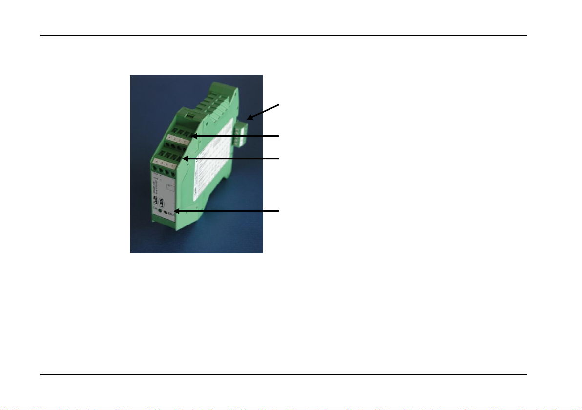
The UMB Analogue/Digital Converter (ANACON) is an intelligent analogue/digital converter with electrical
isolation, suitable for integration into UMB networks. The devices are easily installed on standard EN mounting
rails and networked together by means of mounting rail bus connectors. The 24V feed for the power supply
takes place via the bus connector. Windows software is available for the configuration of the ANACON via
RS232 port and an additional ISOCON (8160.UISO).
Features
2 analogue inputs with 24 bit resolution and signal conditioning for resistance, PT100/PT1000, voltage,
current, frequency and pulses as well as pre-defined settings for a large number of Lufft environmental
sensors. A half-duplex RS485 interface for networking the converters together.
Easy mounting on standard EN mounting rails
Easy networking of up to 32 subscribers via mounting rail bus connectors
24V DC power supply suitable for switchgear cabinets
ESD protection for all interfaces
Configuration via Windows software provided
Functions displayed via LED’s
Low space requirement; width approx. 23mm/module
Low energy consumption / dissipation

UMB Analogue/Digital Converter ANACON Operating Manual
6 G. Lufft Mess- und Regeltechnik GmbH, Fellbach, Germany
ANACON UMB Analogue/Digital Converter
Summary
Status LED’s
Input Channel B
Input Channel A
Power supply & RS485 bus
interface

Operating Manual UMB Analogue/Digital Converter ANACON
G. Lufft Mess- und Regeltechnik GmbH, Fellbach, Germany 7
Analogue Inputs Channel A and Channel B
ANACON-UMB
Connection
Channel B
Channel A
PIN
Name
1
Power, Sensor Power Supply
2
ANA_+, Sense High Input
3
ANA_I, Force Low Input
4
ANA_-, Force High Input

UMB Analogue/Digital Converter ANACON Operating Manual
8 G. Lufft Mess- und Regeltechnik GmbH, Fellbach, Germany
Mounting Rail Bus Connector
NOTE: The assembly must take place on a grounded DIN rail !
Earth 24V Power Supply, Feed
+24V Power Supply, Feed
B1, Internal Bus
A1, Internal Bus

Operating Manual UMB Analogue/Digital Converter ANACON
G. Lufft Mess- und Regeltechnik GmbH, Fellbach, Germany 9
Status LED’s
There are 2 LED’s on the front side of the device in order to display the correct configuration and functioning of
the ANACON. Their meanings are as follows:
Red LED: - If this LED lights up permanently after switch-on there is a configuration fault.
- If this LED lights up during operation an unforeseen fault has occurred; the device must be
reset.
Green LED: - This LED flashes briefly (20ms) every 10 seconds to display the function of the device.
- This LED lights up for a longer period (>500ms) during measurement.

UMB Analogue/Digital Converter ANACON Operating Manual
10 G. Lufft Mess- und Regeltechnik GmbH, Fellbach, Germany
Configuration
The ANACON modules are all supplied from the factory with ID 1. If several modules are installed in a UMB
network, it must be ensured that all modules on the network have a different ID. The following steps should be
taken in order to configure the device:
1. Clip a mounting rail bus connector onto the Din rail and connect the 24V supply with the aid of the
connector provided. Please ensure that the polarity and pin assignment are correct on connection.
Incorrect connection can cause the destruction of the ANACON module!
2. Next mount the ANACON module which you wish to configure.
3. For the connection to the RS232 port of your PC a additional ISOCON (8160.UISO) is necessary. Clip
the ISOCON also on the mounting rail and connect the module to your PC via the RS232 interface.
4. Set the desired ID and channel configuration using the UMB-Config-Tool software. You can enter the
configured ID in the inscription field on the front side of the module.
5. The ANACON is now ready for operation and can be detached from the DIN rail. Please repeat steps 2
to 5 for all additional ANACON modules.

Operating Manual UMB Analogue/Digital Converter ANACON
G. Lufft Mess- und Regeltechnik GmbH, Fellbach, Germany 11
Installation and Commissioning
1. First configure all the modules using the UMB-Config-Tool configuration software in accordance with
your requirements (see Configuration chapter).
2. Clip the required number of mounting rail bus connectors onto the DIN rail and then connect all the
ANACON modules.
3. Connect the sensors to channels A and B of the ANACON module. Please note that a fixed assignment
is specified for channels A and B for the combined sensors for temperature and relative humidity as well
as the wind speed and wind direction sensors. A summary of the sensor connection scheme is provided
in the table below.
4. Now connect the 24V power supply to the mounting rail bus connectors.
5. Connect your host system to any desired ISOCON RS232 interface. The equipment is now ready for
operation.
Connecting the ANACON modules to the DIN rail
ATTENTION: Only mount or remove modules
from the DIN rail when the power is switched
off
The assembly must take place on a grounded
DIN rail!

UMB Analogue/Digital Converter ANACON Operating Manual
12 G. Lufft Mess- und Regeltechnik GmbH, Fellbach, Germany
Table: Sensor connection scheme
8160.UANA
Channel A
Channel B
Input
Pin1
Pin2
Pin3
Pin4
Pin1
Pin2
Pin3
Pin4
Resistance (3 wire),
PT100/PT1000
Voltage
V+
V-
V+
V-
Current self powered
I-
I+
I-
I+
Current ANACON powered
I+
I-
I+
I-
Frequency
F-
F+
F-
F+
Impulse/ Digital Input
D-
D+
D-
D+
Lufft Sensors
8160.TF (T)
red
red
white
red
red
white
8160.TFF (T/H)
brown
orange
black
red
yellow
8355.03 (Baro)
red
orange
red
orange
8368.01 (WS/WD)
orange
black
black
brown
brown
black
8352.USH4M/US6M
blue
brown
blue
orange
8353.02/4/5
brown
orange
brown
orange

Operating Manual UMB Analogue/Digital Converter ANACON
G. Lufft Mess- und Regeltechnik GmbH, Fellbach, Germany 13
Sensor Channel List
Channel assignment equipment class 6 universal measurement transmitters
UMB Channel
Measurement Range
Act
Min
Max
Avg
Special
Input
Variable
Min
Max
Unit
Temperature
100
120
140
160
A
temperature
-200.0
450.0
°C
105
125
145
165
A
temperature
-328.0
842.0
°F
101
121
141
161
B
temperature
-200.0
450.0
°C
106
126
146
166
B
temperature
-328.0
842.0
°F
110
130
150
170
dewpoint
-200.0
450.0
°C
111
131
151
171
dewpoint
-328.0
842.0
°F
Humidity
201
221
241
261
B
relative humidity
0,0
100,0
%
206
226
246
266
B
absolute humidity
g/m²
211
231
251
271
B
mixing ratio
g/kg
Pressure
300
320
340
360
A
air pressure
0
1200
hPa
305
325
345
365
A
abs. air pressure
0
1200
hPa
301
321
341
361
B
air pressure
0
1200
hPa
306
326
346
366
B
abs. air pressure
0
1200
hPa

UMB Analogue/Digital Converter ANACON Operating Manual
14 G. Lufft Mess- und Regeltechnik GmbH, Fellbach, Germany
Wind
Vect. avg
400
420
440
460
480
A
Wind Speed
0
100.0
m/s
405
425
445
465
485
A
Wind Speed
0
360.0
km/h
410
430
450
470
490
A
Wind Speed
0
223.7
mph
415
435
455
475
495
A
Wind Speed
0
194,4
kts
501
521
541
561
581
B
Wind Direction
0
359.9
°
Precipitation
600
A
precipitation absol.
mm
601
B
precipitation absol.
mm
620
A
precipitation diff.
mm
621
B
precipitation diff.
mm
640
A
precip. intens.
mm/h
641
B
precip. intens.
mm/h
Digital input
700
720
740
760
A
Digital Input
0
1
701
721
741
761
B
Digital Input
0
1
Voltage
10000
10020
10040
10060
A
Voltage
0
1000
mV
10001
10021
10041
10061
B
Voltage
0
1000
mV
Current
10100
10120
10140
10160
A
Current
0
24
mA
10101
10121
10141
10161
B
Current
0
24
mA

Operating Manual UMB Analogue/Digital Converter ANACON
G. Lufft Mess- und Regeltechnik GmbH, Fellbach, Germany 15
Resistance
10200
10220
10240
10260
A
Resistance
0
2000
Ohm
10201
10221
10241
10261
B
Resistance
0
2000
Ohm
Frequency
10300
10320
10340
10360
A
Frequency
10
10000
Hz
10301
10321
10341
10361
B
Frequency
10
10000
Hz
Pulses
10500
A
impulse absol.
0
65520
pulse
10501
B
impulse absol.
0
65520
pulse
10520
A
impulse diff.
0
65520
pulse
10521
B
impulse diff.
0
65520
pulse

UMB Analogue/Digital Converter ANACON Operating Manual
16 G. Lufft Mess- und Regeltechnik GmbH, Fellbach, Germany
Technical Data
Power supply
Power supply 24VDC +/- 10%
Power consumption < 50mA at 24V; excluding sensor
Connection Phoenix bus connector, gold, 5 pole
Function display Green LED, flashes every 10 seconds
RS485 interface internal bus
Standard RS485 2 wire, half-duplex
Transmission type Protocol-transparent, 8 data bits, 1 stop bit, no parity
Tri-State 2 bit after stop bit edge
Transmission rate 19200 baud
Connection Phoenix bus connector, gold, 5 pole, maximum 8A
24V output max. 2 A (note the maximum current of the internal bus)

Operating Manual UMB Analogue/Digital Converter ANACON
G. Lufft Mess- und Regeltechnik GmbH, Fellbach, Germany 17
Measurement Variables
Variable
Measurement Range
Resolution
Accuracy (25°C)
Voltage
0 ... 100mV
0.02% of EV
+/- 0.1% of m.v. +/- 2 digits
Voltage
0 ... 1000 mV
0.02% of EV
+/- 0.1% of m.v. +/- 2 digits
Current *1)
0 ... 20 mA (max:
24mA)
0.02% of EV
+/- 0.1% of m.v. +/- 2 digits
Current *2)
4 …20mA (max:
24mA)
0.02% of EV
+/- 0.1% of m.v. +/- 2 digits
Resistance
0 ... 200 Ohm
0.02% of EV
+/- 0.1% of m.v. +/- 2 digits
Resistance
0 ... 2000 Ohm
0.02% of EV
+/- 0.1% of m.v. +/- 2 digits
Temperature with
PT100
-200 ... 500 °C
0.02°C for
(-50°C<t<150°C) otherwise
0.1°C
+/- 0.1°C for
(-50°C<t<150°C) otherwise +/- 0.5°C
Temperature with
PT1000
-200 ... 500 °C
0.02°C for
(-50°C<t<150°C) otherwise
0.1°C
+/- 0.1°C for
(-50°C<t<150°C) otherwise +/- 0.5°C
Frequency *3)
0 ... 1000 Hz
0.02% of EV
+/- 0.1% of m.v. +/- 2 digits
Frequency *3)
0 ... 10 kHz
0.02% of EV
+/- 0.1% of m.v. +/- 2 digits
Pulses *4)
0 ... 65520
1 pulse
Digital input *5)
0 / 1
1. Shunt resistance 51 Ohms
2. Shunt resistance 51 Ohms, voltage on Pin 1 in ANACON powered mode approx. 12V
3. Pulse duty ratio 50%, internal resistance approx. 500 Ohms, Uhigh>6V, Ulow<3V
4. Pulse length > 100µs, pulse spacing > 100µs, internal resistance approx. 500 Ohms, Uhigh>6V, Ulow<3V
5. Internal resistance approx. 500 Ohms, Uhigh>6V, Ulow<3V

UMB Analogue/Digital Converter ANACON Operating Manual
18 G. Lufft Mess- und Regeltechnik GmbH, Fellbach, Germany
LUFFT Sensors
Sensor
Measurement
Variable
Measurement
Range
Physical
Variable
Physical
Measurement
Range
Temperature Sensor
8160.TF
Temperature PT100
-50 ... 100 °C
Resistance
60.34 –138.5
Ohms
Temperature/Humidity
Sensor 8160.TFF
Temperature
PT1000
-30 ... 70 °C
Resistance
882.2 –1270.8
Ohms
Humidity
0 ... 100 %
RH
Frequency
Barometric Air Pressure
Sensor 8355.03
Air Pressure
0 ... 1200 hPa
Current
4 ... 20 mA
Wind Speed and Wind
Direction 8368.01
Wind Speed
0.9 ... 50 m/s
Voltage
0 - 1000 mV
Wind Direction
0 ... 358 °
Resistance
0 –1000 Ohms
Wind Speed and Wind
Direction
8352.USH4M/US6M
Wind Speed
0 ... 60 m/s
Current
4 - 20 mA
Wind Direction
0 ... 359 °
Current
4 - 20 mA
Rain Gauge with 1mm;
0.2mm; 0.1mm
resolution
Precipitation
Pulses
0....65620

Operating Manual UMB Analogue/Digital Converter ANACON
G. Lufft Mess- und Regeltechnik GmbH, Fellbach, Germany 19
Storage conditions
Permissible ambient temp. -40 ... 70°C
Permissible rel. humidity 0 ... 95% RH (non-condensing)
Operating conditions
Permissible operating temp. -30 ... 60°C
Permissible rel. humidity 0 ... 95% RH (non-condensing)
Housing
Material PA-V0, green
Width x Height x Depth 22.5 x 99 x 118.6 mm
Protection class IP20
Weight approx. 120 g
Connections COMBICON plug-in connectors 0.2 –2.5 mm² (AWG 24 –12)

UMB Analogue/Digital Converter ANACON Operating Manual
20 G. Lufft Mess- und Regeltechnik GmbH, Fellbach, Germany
Maintenance and Care
The product is designed in such a way as to require no maintenance. It does not contain any parts (e.g.
batteries) requiring maintenance or exchange.
Disposal
The device must be disposed of in accordance with European Directives 2002/96/EC and 2003/108/EC
(waste electrical and electronic equipment). Waste equipment must not be disposed of as household
waste! For environmentally sound recycling and the disposal of your waste equipment please contact a
certified electronic waste disposal company.
Manufacturer
For matters of guarantee or repair please contact:
G. Lufft Mess- und Regeltechnik GmbH
Gutenbergstraße 20
D-70736 Fellbach
Postfach 4252
D-70719 Fellbach
Germany
Tel: +49(0)711-51822-0
Fax: +49(0)711-51822-41
E-mail: info@lufft.de
Other manuals for 8160.UANA
2
Table of contents
Other Lufft Media Converter manuals
Popular Media Converter manuals by other brands

Belden
Belden Grass Valley SME-1901 Guide to installation and operation

Eltek Valere
Eltek Valere PSC305-LV user manual

HDTV Supply
HDTV Supply HDTVSXHDCP01 operating instructions

Precision Digital Corporation
Precision Digital Corporation PROVU PDA1232 instruction manual

ProVideoInstruments
ProVideoInstruments VECOAX ULTRA BT Series manual

Snell & Wilcox
Snell & Wilcox HD5050 Operator's manual