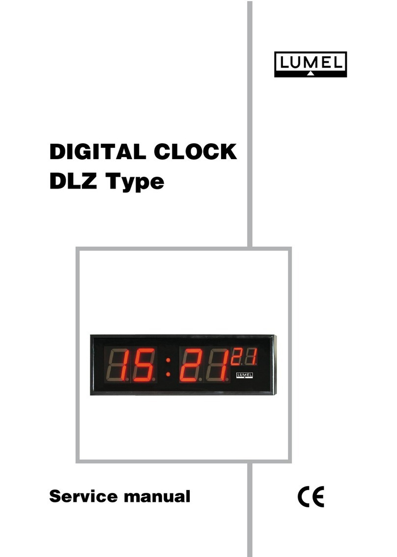
Lumel DZ2 User manual

1
USER’S MANUAL
LARGE SIZE
DIGITAL CLOCKS
DZ2 AND DZ3 TYPES

2

3
Contents
1. APPLICATIONS......................................................................................................... 5
2. CLOCK SET ............................................................................................................. 5
3. BASIC REQUIREMENTS, OPERATIONAL SAFETY ................................................................. 5
4. DESIGN AND INSTALLATION ........................................................................................ 7
5. WIRING CONNECTIONS............................................................................................... 8
6. REGISTER MAP OF THE CLOCK CONTROLLER.................................................................... 9
7. TECHNICAL DATA..................................................................................................... 11
8. ORDERING CODES ................................................................................................... 12
9. BEFORE A FAILURE WILL BE DECLARED ......................................................................... 13
10. MAINTENANCE AND WARRANTY .................................................................................. 13

4

5
1. APPLICATIONS
The DZ digital clock shows the date and time alternately. The quantity switching over is set arbitrarily.
The default value is equal 5 seconds.
These digital clocks are intended to be installed outside and inside shops, by production lines, in sto-
res, refrigeration plants, sports and commercial objects.
The DZ2 clock (digits of 200 mm high) ensures a good readout from 80 m distance. The DZ3 clock
(digits of 300 mm high) ensures a good readout from 120 m distance.
These clocks are offered with digits in 3 versions of colours: red, green and yellow.
DZ clocks co-operate with an external DCF receiver, atomic time standard. These clocks are synchro-
nized every now and again with the time standard.
They have additionally the RS-485 interface with MODBUS RTU protocol. This interface enables to set
the clock in case when the DCF signal is too weak and there is no possibility to synchronize the clock
with the time standard.
The luminosity of digits is programmed by the user taking into consideration the night-time.
2. CLOCK SET
The set consists of:
- digital clock 1 pc.
- user’s manual 1 pc.
- warranty card 1 pc.
- female connector on the cable 2 pcs
- DCF receiver with the cable 1 pc
When unpacking the watt-hour meter, please check the delivery completeness and whether the
type and version code on the data plate correspond to the order.
3. BASIC REQUIREMENTS, OPERATIONAL SAFETY
Symbols located in this user’s manual mean:
WARNING!
Warning of potential, hazardous situations. Especially important. One must be familiar with
this before connecting the digital clock. The non-observance of notices marked by these
symbols can occasion severe injuries of the personnel and the damage of the device.
CAUTION!
Designates a general useful note. If you observe it, handling of DZ digital clocks is made
easier. One must take note of this, when the digital clock is working inconsistently to the
expectations.
Possible consequences if disregarded!
In the security scope the DZ digital clock fulfils the requirements of the international EN 61010-1 stan-
dard.

6
Remarks concerning the operator safety:
1. General
nThe digital clock is destined to be installed inside or outside buildings.
nNon-authorized removal of the required housing, inappropriate use, incorrect installation or opera-
tion create the risk of injury to personnel or damage to equipment. For more detailed information
please study the user’s manual.
nAll operations concerning transport, installation, and commissioning as well as maintenance must be
carried out by qualified, skilled personnel and national regulations for the prevention of accidents
must be observed.
nAccording to this basic safety information, qualified, skilled personnel are persons who are familiar
with the installation, assembly, commissioning, and operation of the product and who have qualifi-
cations necessary for their occupation.
2. Transport, storage
Please observe the notes on transport, storage and appropriate handling.
Observe the climatic conditions given in Technical Data.
3. Installation
nThe DZ digital clock must be installed according to the regulation and instructions given in this user’s
manual.
nEnsure proper handling and avoid mechanical stress.
nDo not bend any components and do not change any insulation distances.
nDo not touch any electronic components and contacts.
nElectronic devices may contain electrostatically sensitive components, which can easily be dama-
ged by inappropriate handling.
nDo not damage or destroy any electrical components since this might endanger your health!
4. Electrical connection
nBefore switching the digital clock on, one must check the correctness of connection to the network.
nIn case of the protection terminal connection with a separate lead one must remember to connect it
before the connection of the digital clock to the mains.
nWhen working on live instruments or devices, the applicable national regulations for the prevention
of accidents must be observed.
nThe electrical installation must be carried out according to the appropriate regulations (cable cross-
sections, fuses, PE connection). Additional information can be obtained from the user’s manual.
nDo not connect the digital clock to the mains via an autotransformer.
nThe documentation contains information about installation in compliance with EMC (shielding, groun-
ding, filters and cables). These notes must be observed for all CE-marked products.
nThe manufacturer of the installation or installed auxiliary devices is responsible for the compliance
with the required limit values demanded by the EMC legislation.
nThe RS-485 socket serves only for the connection of digital clocks operating with the MODBUS
protocol.
5. Operation
nInstallations including DZ2 or DZ3 digital clocks must be equipped with protection devices accor-
ding to the corresponding standard and regulations for prevention of accidents.
nAfter the digital clock has been disconnected from the supply voltage, live components and power
connections must not be touched immediately because capacitors can be charged.
nThe housing must be closed during operation.
7
6. Maintenance and servicing
nPlease observe the manufacturer’s documentation.
nRead all product-specific safety and application notes in this user’s manual.
nBefore taking the digital clock housing out, one must turn the supply off.
nThe removal of the digital clock housing during the warranty contract period may cause its
cancellation.
4. DESIGN AND INSTALLATION
The clock housing is made of steel sheet with the possibility to fix it on a wall or suspend the digital
clock.
The protection degree is IP54.
Housing dimensions:
DZ2: 1510 ´284 ´77 mm
DZ3: 2020 ´360 ´77 mm
The DCF receiver is fixed separately and should be distant from electromagnetic field sources, current-
carrying wires, big metallic objects, and electronic devices.
If it is possible, the receiver should be situated outside the building. The DCF signal is broadcasted
from Germany in the shape of 0.1 sec. and 0.2 sec. pulses, in one second’ intervals. If the DCF receiver
is properly situated, the receiver diode lights during 0.1 or 0.2 sec and goes out within 0.9 or 0.8 sec.
Fig. 1. Fixing way of the DCF receiver
A complete DCF signal lasts 1 minute, the first synchronization follows after a full minute since the
moment of the place retrieval of the proper signal.

8
Dimensions DZ2 DZ3
L 1510 2020
h 284 360
Fig. 2. Overall dimensions of DZ2 and DZ3 digital clocks and layout of holes and suspension clamps
5. WIRING CONNECTIONS
The clock set includes two female cable connectors: a 3-pole supplying connector and a 4-pole inter-
face connector.
The DCF receiver is delivered with a plug.
One must perform electrical connectors acc. to the Fig. 3.
Fig. 3. Electrical connections

9
Table 1
Fig. 4. Description of sockets to connect the supplying network and interface
Wires:
maximal wire cross-section: 1.5 mm2
maximal cable diameter: 4.5... 7 mm
A shielded double spiral wire is recommended to connect the interface
Connect the shield with the PE terminal of the G2 interface socket.
6. REGISTER MAP OF THE CLOCK CONTROLLER
The MODBUS RTU communication protocol has been implemented in the controller.
Applied markings:
R – readout
W – writing
DZ configuration registers – registers 4000...4037
All configuration registers are 16-bit registers of unsigned integer type.
Register
address operations Range Description
4000 RW 1...247 DZx clock type address in MODBUS network
4001 RW 0...3
Operating mode of the interface no 1:
0: RTU 8N1
1: RTU 8N2
2: RTU 8E1
3: RTU 8O1
4002 RW 0...9
Baud rate of interface no 1 (b/s):
0 –2400; 1 – 4800; 2 – 9600; 3 – 14400; 4 –19200;
5–28800; 6–38400; 7– 57600; 8 – 76800 ; 9 –115200
4007 RW 1...100 Luminosity level for the day
4008 RW 1...100 Luminosity level for the night

10
4009 RW 0...2359 Starting hour in the day expressed as:
GG*100 + MM
4010 RW 0...2359 Starting hour in the day expressed as:
GG*100 + MM
4011 RW 5..60 Display time of time/date before switching over.
Controller status
4037 RW 0x00...0xFFFF
Controller status register. Successive bits are flags in-
forming about the lasting or passed event.
Flags can only be erased.
If a write follows into the register, then a logic product
will be performed on the register value with the written
value.
The meaning of bits is as follows:
Bit 15 – Error of RAM memory.
Bit 14 - erroneous settings. Factory
settings were restored
Bit 13 – Setting error of RTC clock or lack
of the correct DCF frame. The
flag is automatically erased in
case of a correct DCF frame.
Bit 12 – A change of summer/winter time
has occured or inversely.
Bit 11 – Break in the panel supply.
Bit 10...5 – no used.
32-bit registers of float type
7565 RW .... Present time in YY format , MMDD
7566 RW ... Present time in GG format, MMSS
(continuation) Table 1

11
7. TECHNICAL DATA
Power consumption max 45 W
Readout field:
- DZ2 10 characters of 200 mm high;
8 digits + 2 special characters (colon, hyphen, comma)
digit colour: red, yellow, green,
- DZ3 10 characters of 300 mm high;
8 digits + 2 special characters (colon, hyphen, comma)
digit colour: red, yellow, green.
Communication:
- serial interface RS - 485
- transmission protocol MODBUS RTU
Reaction to decays and supply recoveries:
- preservation of configuration data
- continued operation after supply recovery
Protection degree ensured by the housing IP 54
Dimensions:
- DZ2 - width: 1510 mm
- height: 285 mm
- depth: 77 mm
- DZ3 - width: 2020 mm
- height: 360 mm
- depth: 77 mm
Reference conditions and rating operating conditions:
- operating temperature -10...23...55°C
- storage temperature -20... 80°C
- humidity 25... 95%
- supply 85... 253 V
- external magnetic field 0...40...400 A/m
- operating position any
- heating time 1 minute
Standards fulfilled by the digital clock:
Electromagnetic compatibility:
- noise immunity acc. to EN 61000-6-2
- noise emission acc. to EN 61000-6-4
Safety requirements
According to EN 61010-1 standard:
lisolation ensured by the housing: basic
lisolation between circuits: basic
linstallation category: III
lpollution level: 2
lmaximal phase-to-earth voltage:
- supply 300 V a.c.
- interface 50 V a.c.

12
8. ORDERING CODES
ORDERING EXAMPLE
Code: DZ 2 - R 00 means:
DZ2 – digital clock with digits of 200 mm high,
R– digit colour on display: red,
00 – standard version
DIGITAL CLOCK DZ X- X XX
Digit height:
200 mm ....................................................................... 2
300 mm........................................................................ 3
Digit colour on the display field:
red....................................................................................... R
yellow...................................................................................Y
green................................................................................... G
Version:
standard..................................................................................... 00
custom-made* ........................................................................... XX
* the code number will be established by the manufacturer

13
Table 2
9. BEFORE A FAILURE WILL BE DECLARED
In case of incorect symptoms, please to get acquinted with the table below.
SYMPTOMS PROCEDURE
1. Messages are not displayed Check the connection of the network cable
2. flashing of diode point on the last
digit of the clock Lack of synchronization with the time standard
3. Lack of certainty if all character fields
are efficient.
The test clock is starting each time when the supply is
turned on.
Character fields are lighted successively by segments
and simultaneously in all digits. If differently, contact the
nearest servicing workshop.
4.The clock does not communicate
with the computer via the RS-485
interface.
Check the setting of the RS-485 port or the converter:
Default setting of the panel:
Address 1, Mode RTU 8N2, baud rate 9600 kb/s
10. MAINTENANCE AND WARRANTY
DZ2 and DZ3 digital clocks do not require any periodical maintenance.
In case of some incorrect operations:
1. In the period of 12 months since the date of purchase:
One should take the digital clock down from the installation and return it to the Manufacturer
Quality Control Dept. If the unit has been used in compliance with the instructions, the
Manufacturer warrants to repair it free of charge.
2. After the warranty period:
One should turn over the digital clock meter to repair it in a certified service workshop. The
disassembling of the housing causes the cancellation of the granted warranty. Spare parts are
available for the period of five years from the date of purchase.
Our policy is one of continuous improvement and we reserve the right to make changes
in design and specifications of any products as engineering advances or necessity
requires and revise the above specifications without notice.
This user’s manual has been designed as a tool to help you get the most from the ordered product.
We hope that you carefully read this manual and follow its recommended procedures so that you will
be able to properly use and maintain this product.
We welcome any suggestions you may have that could help us improve the product and this user’s
manual.

14

15

16
DZ2-07
Lubuskie Zak³ady Aparatów Elektrycznych LUMEL S.A.
ul. Sulechowska 1
65-022 Zielona Góra - Poland
Tel. (48-68) 329 51 00 (exchange)
Fax: (48-68) 329 51 01
http://www.lumel.com.pl
Export Department:
Tel: (48-68) 329 53 02
Fax.: (48-68) 325 40 91
e-mail: [email protected]
MEASUREMENT
CONTROL
RECORDING
SALES PROGRAM
nDIGITAL and BARGRAPH PANEL METERS
n
MEASURING TRANSDUCERS
n
ANALOG PANEL METERS (DIN INSTRUMENTS)
n
DIGITAL CLAMP-ON METERS
n
INDUSTRIAL PROCESS and POWER CONTROLLERS
n
CHART and PAPERLESS RECORDERS
n
LARGE SIZE DISPLAY PANELS
n
ELEMENTS OF INTEGRATION SYSTEMS
n
ACCESSORIES FOR MEASURING INSTRUMENTS (SHUNTS)
n
MEASURING SYSTEMS (ENERGY, HEAT, CONTROL)
n
CUSTOM-MADE PRODUCTS
WE ALSO OFFER OUR SERVICES IN THE PRODUCTION OF:
n
ALUMINIUM ALLOY PRESSURE CASTINGS
n
PRECISION ENGINEERING and THERMOPLASTIC PARTS
n
SUBCONTRACTING of ELECTRONIC DEVICES (SMT)
n
PRESSURE CASTINGS and OTHER TOOLS
QUALITY PROCEDURES:
According to ISO 9001 and ISO 14001 international requirements.
All our instruments have CE mark.
For more information, please write to or phone our Export Department
This manual suits for next models
1
Table of contents
Other Lumel Clock manuals