Lumina Power CCPF-3500 Series User manual

02100004 Rev 1 CCPF-3500-XX User Manual Page 1 of 15
26 Ward Hill Ave., Bradford, MA 01835
Phone: 978-2 1-8260 Fax: 978-2 1-8262
USER MANUAL
CCPF-3500-XX
CCPF- 000-XX
3.5 to .0 kJ/s Capacitor Charging
Power Supply Series

02100004 Rev 1 CCPF-3500-XX User Manual Page 2 of 15
Table of Contents
1.Descrip ion of CCPF-3500-XX Power Supply ........................................................... 3
2.Explana ion of Symbols............................................................................................... 4
3.CCPF-3500 Specifica ions .......................................................................................... 5
4.CCPF-3500 In erface ................................................................................................... 6
5.Typical Applica ions.................................................................................................... 9
5.1 Using a CCPF wi h a pulse forming ne work (PFN) ............................................. 9
5.2 Using a CCPF wi h a par ial discharge ne work (Reservoir Charging) .............. 10
5.3 Using a CCPF wi h mul iple PFNs or capaci ors ................................................ 11
6.Warnings .................................................................................................................... 12
7.Ins alla ion ................................................................................................................. 13
8.Produc Limi ed Warran y ......................................................................................... 14
9.Service ....................................................................................................................... 15
Tables and Figures
Table 1, CCPF In erface ..................................................................................................... 6
Table 2, CCPF Connec ions .............................................................................................. 13
Figure 1, CCPF-3500 Block Diagram ................................................................................ 3
Figure 2, CCPF-3500 In erface Schema ic ......................................................................... 7
Figure 3, CCPF-3500 Mechanical Ou line Drawing .......................................................... 8

02100004 Rev 1 CCPF-3500-XX User Manual Page 3 of 15
1. Description of CCPF-3500-XX Power Supply
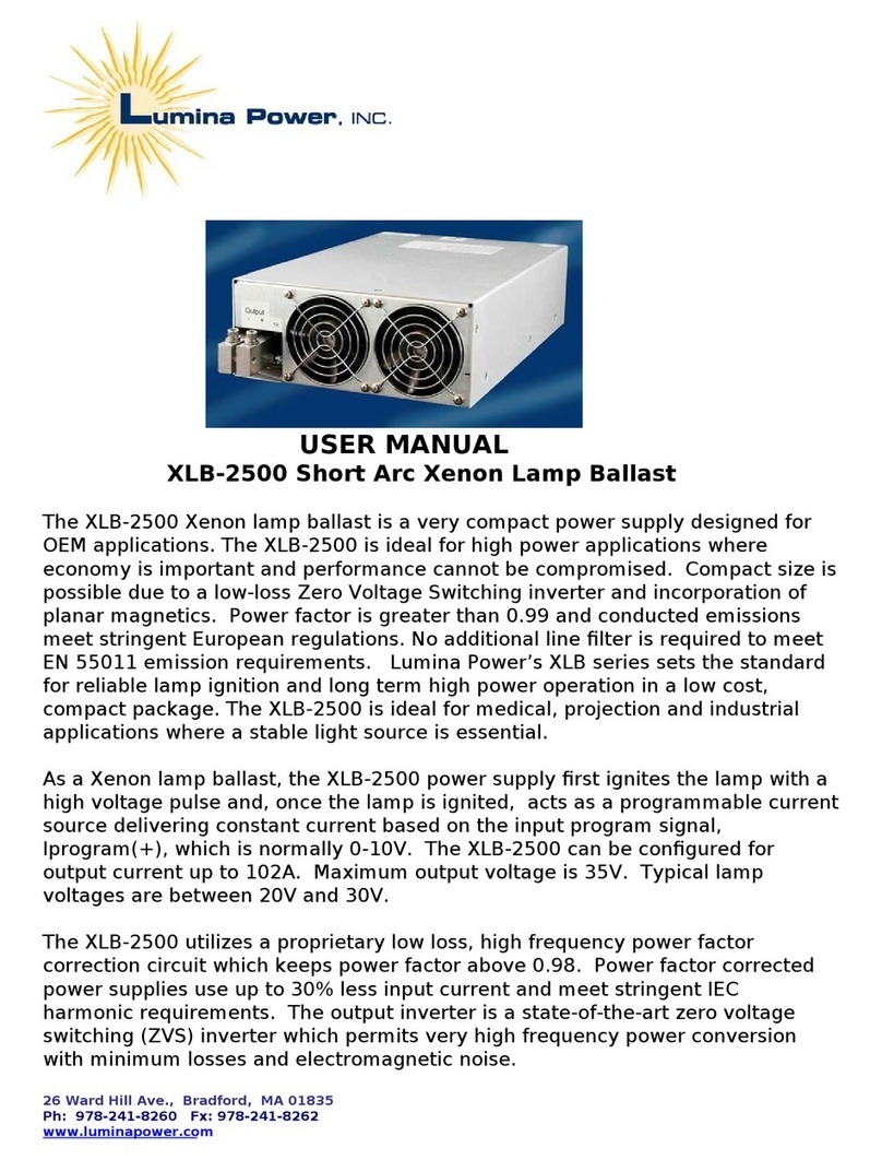
The CCPF-3500/4000-XX capaci or charging power supplies are designed for OEM laser
manufac urers. The CCPF-3500 power supply provides up o 3500 J/s average charging
power for full discharge PFN applica ions, while he CCPF-4000 power supply provides
up o 4000 J/s charging power for reservoir capaci or banks. The main power ou pu
provides a cons an curren o charge up a capaci or o he programmed value.
The CCPF-3500/4000-XX can be configured for maximum ou pu vol ages up o 4000V
where he XX indica es he maximum ou pu vol age. As an example, a CCPF-3500
configured for 1000V maximum ou pu vol age is designa ed as a CCPF-3500-1P, where
P indica es a posi ive ou pu which is he s andard polari y. An op ional +24VDC ou pu
is available for auxiliary power.
The CCPF akes AC inpu from 200 – 240VAC, 50/60 Hz and rec ifies i by he inpu
rec ifier bridge. The rec ified vol age is boos ed o non-isola ed 400 VDC by he Power
Fac or Correc ion (PFC) circui . The purpose of he PFC is o force he inpu curren o
be in phase wi h he inpu vol age, close o uni y power fac or; such ha from 20% o
100% load he power fac or is be er han 98%. The PFC also produces he auxiliary
power for he fans and con rol circui s. The 400 VDC power is he source for he inver er
o genera e he high ou pu vol age for he capaci or load.
Figure 1, CCPF-3500 Block Diagram

02100004 Rev 1 CCPF-3500-XX User Manual Page 4 of 15
2. Explanation of Symbols
Hazard: This equipmen produces high vol ages
which can be fa al. Only service personnel of Lumina
Power, Inc. are qualified o service his equipmen .
High Voltage Present.
This power supply
produces le hal high vol ages. Only service personnel
of Lumina Power, Inc., are qualified o service his
equipmen . Only qualified service personnel are
permi ed o ins all his power supply.
Chassis Ground:
This symbol where he pro ec ive
ear h ground connec ion is loca ed.

02100004 Rev 1 CCPF-3500-XX User Manual Page 5 of 15
3. CCPF-3500/ 000-XX Speci=cations
XX indica es ou pu vol age wi h P for posi ive and N for nega ive.
Input
Vol age 200 - 240 VAC, single phase
Curren 22 A maximum a 200 VAC and 18.4A maximum a 240 VAC
Frequency 47 - 64Hz
Output
Power: 3500 J/s average charge ra e for full discharge PFN
4000 J/s maximum charge ra e for reservoir charging
See sec ion 5 Typical Applica ions below
Ou pu Vol age Fixed vol age be ween he ranges of 400VDC – 4.0kVDC
(fac ory configured, con ac fac ory for vol ages > 4kVDC)
Polari y Posi ive or Nega ive (fac ory configured)
Efficiency >80% a full ou pu
Regula ion: 0.5% @100Hz
Aux. Ou pu +24VDC @ 3A (op ional fea ure)
Interface
Connec or 15 Pin “D” Sub Female
Vol age Program 0-10V for 0-Max Vol age
Vol age Moni or 0-10V for 0-Max Vol age
Inhibi /Rese Inpu , low level (high level op ional, con ac fac ory)
End of Charge Ou pu indica ion
Overvol age Ou pu indica ion
Over emp Ou pu indica ion
Overload Ou pu indica ion
+15V Aux Power
Environment
Opera ing Temp 0 o 40 oC
S orage -20 o 85 oC
Humidi y 0 o 90% non-condensing
Cooling Forced air
Al i ude and Pressure 2000 me ers maximum, 80 o 103 kPa
Dimensions Please see Figure 3, CCPF-3500 Mechanical Ou line Drawing
Ou line 14.2 inch leng h, 5.5 inch wide, 6.0 inch high
(does no include moun ing flanges or elec rical erminals)

02100004 Rev 1 CCPF-3500-XX User Manual Page 6 of 15
. CCPF-3500 Interface
Connector Type 15 pin D-sub Female
Refer to Figure 2, CCPF-3500 Interface Schematic
Table 1, CCPF Interface
Pin # Pin Name Functional Level Description
Inhibit/Fault
Reset
!"#$#%&'% %
&()%* "!& %&(
%"'"&&'"&"% #& "%+&(
% , , % %'%- %""&
."!& ","&"!& #"#'"#%( /
Over-Temp
Fault
"&
/
"'
%"
"%
Indica es an in ernal high empera ure condi ion. When an over
empera ure faul occurs, he signal is pulled ei her o GND or
15V/5V based on specific cus omers’ requiremen . Please
refer o he es da a shee for a specific power supply o see
how ha uni is configured. A N/O (a N/C swi ch is available)
hermal swi ch closes during an over empera ure condi ion.
Under normal empera ure condi ions, he over empera ure
ou pu is pulled o 15V via a 4.99k resis or. For a 5V in erface,
a 2.49k resis or is in parallel wi h he hermal swi ch. The
hermal swi ch will rese i self when he empera ure has been
reduced by approxima ely 20˚C.
0/ No connect "&-"(! *'%#- % #1 *
'#"&( /
Voltage
Program
2
2 -"3
Ou pu is programmed ex ernally wi h a 0 o +10V signal for 0
o Vou max. See no e 1. Note: Accuracy and linearity will be
compromised when operating below 20% of the max value.
4
OVERVOLTAGE /
OVERLOAD / NO
LOAD STATUS
INDICATOR
5
, %&"*
When he ou pu is open or shor ed circui ed, or if he capaci or can’ be
fully charged o he programmed level in a given ime, he Over-Load
Faul will la ch Low and he power supply will shu down o pro ec
i self. Typically, i is 15V a an open collec or wi h a 4.99k pull up
during normal opera ion. To Clear he Faul : Correc he problem a he
load and oggle he Inhibi signal or recycle he AC inpu .
6
Vout Peak
Hold
2
2 -"3
7 "8* ##%#' ,&" -%
- #""%3-" &( #*9
: Vout Monitor
2
2 -"3;%,&" 9
< +15V @0.1A
= >?'%#- % %'"# -"3--
#%% -+
End of Charge
Status
Indicator
?"%
"*#"% *
&"
7%%"-
When he load capaci or is fully charged o he programmed level, he
EOC signal will go Low hru an NPN ransis or. The signal is Normally
High via a 4.99k pulled up o 15V. The EOC signal will oggle when he
power supply is refreshing he load cap. La ched EOC is op ional: The
EOC signal will la ch Low when he capaci or is fully charged and s ays
Low un il he cap is discharged and he Inhibi signal is asser ed.
0 Ground
)%*% %'%#%& %'"# "&
02100004 Rev 1 CCPF-3500-XX User Manual Page 7 of 15
Figure 2, CCPF-3500 Interface Schematic
No es:
1. Analog vol age range of 0-5V available per cus omer reques .
2. O her in erface configura ions are available o conform o older capaci or charger
models or cus omer reques s, con ac Lumina Power for any in erface changes.

02100004 Rev 1 CCPF-3500-XX User Manual Page 8 of 15
Figure 3, CCPF-3500 Mechanical Outline Drawing

02100004 Rev 1 CCPF-3500-XX User Manual Page 9 of 15
5. Typical Applications
5.1 Using a CCPF with a pulse forming network (PFN)
The above block diagram shows a ypical connec ion be ween a CCPF capaci or charging
power supply and a well ma ched pulse forming ne work. In a ypical opera ion, when
he CCPF is ENABLED via Pin 1, he INHIBIT func ion, he CCPF will charge up he
PFN capaci or o he programmed value and hen ransmi an END OF CHARGE signal
o he user. Before discharging he load capaci or in o he PFN, he CCPF should be
disabled via he INHIBIT func ion. Once he PFN is comple ely discharged and he SCR
has comple ely urned off, he charging func ion can be ENABLED via he INHIBIT
func ion and he CCPF will charge he capaci or again o he programmed value. PFN
designers may choose o include a limi ing resis or and a reversal pro ec ion diode o
pro ec he power supply if here is any possibili y of an arc in he PFN circui ry.

02100004 Rev 1 CCPF-3500-XX User Manual Page 10 of 15
5.2 Using a CCPF with a partial discharge network (Reservoir
Charging)
In his applica ion, he power supply is ENABLED via he INHIBIT func ion and charges
up he capaci or bank o he programmed vol age. The IGBT will deliver shor , high
curren pulses o he flashlamp. The power supply does no need o be inhibi ed during
his process and con inuously main ains he capaci or bank charged.

02100004 Rev 1 CCPF-3500-XX User Manual Page 11 of 15
5.3 Using a CCPF with multiple PFNs or capacitors
In applica ions where he power supply has o charge 2 or more separa e capaci ors which
are discharged a differen imes, diodes mus be used in series wi h he ou pu o preven
one cap from discharge in o he o her. Also, a resis or mus be in parallel wi h each diode
o help he power supply o “see” he cap vol age which is now blocked by he diodes.
Failure o add he parallel resis ors will resul in over charging he cap as he power
supply does no see he real vol age on he caps.
The diodes mus have vol age ra ed a leas 300V higher han he max vol age and 2 imes
he curren .
The resis or values are calcula ed as follows:
R (in Ohm) >= 100 * Vou .
P (in Wa s) >= V^2 /R.

02100004 Rev 1 CCPF-3500-XX User Manual Page 12 of 15
6. Warnings
WARNING : Only Lumina Power, Inc. qualified service personnel are allowed o
remove he covers and service his equipmen .
WARNING : NEVER OPERATE THE POWER SUPPLY:
1. Wi hou providing adequa e pro ec ion of personnel from high vol age.
2. Wi hou proper ground connec ions.
3. Wi hou covers and panels properly ins alled.
4. Wi h cus omer in erlocks defea ed.
5. Wi hou a sui able load for he applica ion and properly ra ed for he
required power dissipa ion.
Warning:
To avoid risk of elec ric shock, his equipmen mus only be
connec ed o a supply mains wi h pro ec ive ear h
Warning:
Equipmen is no sui able for use in presence of a flammable
anes he ic mix ure wi h air or wi h oxygen or ni rous oxide.
Warning:
These power supplies are no provided wi h any isola ion
devices and shall only be used inside o her equipmen ha has
means o isola e i s circui s elec rically from he supply mains
on all poles simul aneously.
High Voltage Present:
This power supply produces le hal high vol ages. Only service
personnel of Lumina Power, Inc., are qualified o service his
equipmen . Only qualified service personnel are permi ed o
ins all his power supply.
Warning:
This equipmen produces high vol ages which can be fa al.
Only service personnel of Lumina Power, Inc. are qualified o
service his equipmen .

02100004 Rev 1 CCPF-3500-XX User Manual Page 13 of 15
7. Installation
These power supplies are designed for and in ended only for ins alla ion in o OEM pulse
forming sys ems.
Only qualified echnicians or qualified assemblers may ins all hese power
supplies.
Only qualified Lumina Power personnel may service hese power supplies.
There are no user serviceable par s in his equipmen .
Required wire and connectors: Refer o Figure 3, CCPF-3500 Mechanical
Ou line Drawing for he loca ions of connec ions. Table 2, CCPF Connec ions
below shows required cables and connec ors:
Table 2, CCPF Connections
Connection Description Required Wire and Connectors
AC Inpu Power 2 Posi ion erminal s rip
#10-32 s ud for ground A leas 12AWG wire
In erface 15 pin “D” female 15 pin “D” male
HV Ou pu
TE/AMP LGH
recep acle
*See no e below
LGH plug wi h coax cable ra ed for a
leas 150% of maximum ou pu
vol age of uni
24V Aux Ou pu
(op ional)
2 Pin Tyco Ma e-N-Lok
Connec or.
Tyco 35077-1 2 Pos Plug
(Digikey P/N A14279-ND)
Tyco 350550-1 Con ac s
(Digikey P/N A1441-ND)
* No e: o her connec ors or flying lead configura ion also available, con ac
Lumina Power for any in erface changes.
Ventilation: This uni is forced air cooled via in ernal DC fans. A clearance of
2” should be main ained a ei her side of he power supply he fan end of he
power supply as well as he grill side of he power supply. Ho air exi s he grill
side and should be duc ed ou of he sys em. Do no le he ho air exhaus
recircula e o he power supply air inle . Fully sealed sys ems should implemen a
hea exchanger sys em o main ain he environmen al condi ions lis in sec ion 3
CCPF-3500/4000-XX Specifica ions on page 5.
IMPORTANT APPLICATON NOTE REGARDING AC INPUT POWER
AC Inpu wires should be a leas #12 AWG,
ra ed for a leas 600V and 105 Degree C.

02100004 Rev 1 CCPF-3500-XX User Manual Page 14 of 15
8. Product Limited Warranty
Lumina Power, Inc., as Seller, warran s ha each Produc sold by i is free of defec s in ma erials and
workmanship. Dura ion of warran y is as follows:
a. All Chassis enclosed produc s are covered for wen y four (24) mon hs from da e of shipmen . Produc s
included bu are no limi ed o he following produc families: CCPF, CCHP, LDY, LDYHC, LDQCW,
XLB (excluding XLB-300), and MLB. Cus om fully enclosed produc s may be covered for he same 24
mon hs. Please consul fac ory for specific erms.
b. All Open Frame produc s are covered for 12 mon hs from da e of shipmen . Open frame power supplies
are defined as any produc ha is no enclosed in a me al or plas ic enclosure. Produc s included bu are no
limi ed o he following produc families: LDPC, LDQPC, XLB-300 and any open frame cus om produc s.
c. All produc s re urned for repair are covered for a period of 6 mon h or he balance of he original
warran y, whichever is longer.
Warran y is no ransferable o par ies ou side of original Buyer's corpora e or educa ional organiza ion.
Seller will have sole discre ion in making de ermina ion of validi y of warran y if he Produc is ransferred
o a differen user group han he original Buyer.
Normal wear and ear and i ems expendable in normal use are no covered by his warran y. All warran y
repair or replacemen of par s shall be limi ed o Produc malfunc ions, which, in he sole opinion of Seller,
are due or raceable o defec s in original ma erials or workmanship. Such de ermina ion will be made when
he Produc is re urned o he Seller's fac ory, ranspor a ion prepaid by he Buyer, wi hin he warran y
period.
All obliga ions under his warran y shall cease immedia ely in he even of abuse, acciden , al era ion,
misuse, or neglec of he Produc . Use and service of he Produc in a manner no in accordance wi h he
Owner's Manual (if furnished) will likewise cause all obliga ions under his warran y o cease. Repaired or
replacemen par s are warran ed only for he remaining unexpired por ion of he original warran y period
for he Produc . Af er expira ion of he applicable warran y period, Buyer shall be charged a he hen
curren prices for par s, labor and ranspor a ion.
Seller has no responsibili y under his warran y for he cos of any work (ma erial, labor, and/or o her
expenses) performed by or incurred by Buyer or any hird par y for modifica ion or repair of he Produc
unless specifically au horized in advance in wri ing by Seller.
Reasonable care mus be used o avoid hazards. Seller expressly disclaims responsibili y for loss or damage
caused by use of i s Produc s o her han in accordance wi h proper opera ion procedures. O her han hose
expressly s a ed herein, here are no o her warran ies of any kind, expressed or implied, and specifically
included bu no by way of limi a ion are he implied warran ies of fi ness or merchan abili y for a
par icular purpose.
I is unders ood and agreed he seller’s liabili y whe her in con rac , in or , under any warran y, in
negligence or o herwise shall no exceed he re urn of he amoun of he purchase price paid by he
purchaser and under no circums ance shall seller be liable for special, indirec , inciden al or consequen ial
damages. The price s a ed for he produc is a considera ion in limi ing seller's liabili y. No ac ion,
regardless of form, arising ou of he ransac ions of his agreemen may be brough by purchaser more han
one year af er he cause of ac ion has accrued.
Seller’s maximum liabili y shall no exceed and buyer's remedy is limi ed o ei her (i) repair or replacemen
of he defec ive par of produc , or a seller's op ion (ii) re urn of he produc and refund of he purchase
price, and such remedy shall be he buyer's en ire and exclusive remedy.

02100004 Rev 1 CCPF-3500-XX User Manual Page 15 of 15
9. Service
Rev ECO Descrip ion Doc C rl Da e App
1 7612 Ini ial Release MJ 08/17/2016 EK
This unit contains no user serviceable parts. Service and repair
should be performed only by quali=ed personnel from Lumina Power, Inc.
For more information contact
Lumina Power, Inc.
26 Ward Hill Ave.,
Bradford, MA 01835
Ph: 978-2 1-8260
Fx: 978-2 1-8262
This manual suits for next models
1
Table of contents
Other Lumina Power Power Supply manuals

Lumina Power
Lumina Power LDD-3000 User manual

Lumina Power
Lumina Power CCPF-500 Series User manual

Lumina Power
Lumina Power LDD-600 Series User manual

Lumina Power
Lumina Power LDD-3000 User manual

Lumina Power
Lumina Power LDD-100 User manual

Lumina Power
Lumina Power HPP-1000 User manual

Lumina Power
Lumina Power XLB-2500 User manual

Lumina Power
Lumina Power CCPF-1500 User manual