luminii Easy-Link User manual

*LUMINII RESERVES THE RIGHTS TO CHANGE SPECIFICATION & INSTRUCTION WITHOUT NOTICE
Instruction page index:
Mounting & Powering fixture
Sensor/Switch installation
Sensor/Switch programming instructions
2
3
4
Easy-Link - Installation Instructions, LED Cabinet Luminaires
Models EL-
REV0.4 03152019
6264 Oakton St
Morton Grove
IL 60053
T 224.333.6033
F 224.757.7557
www.luminii.com
Page 1 of 4
PORTABLE CABINET
LED LUMINAIRE
E475914

6264 Oakton St
Morton Grove
IL 60053
T 224.333.6033
F 224.757.7557
www.luminii.com
Easy-Link - Installation Instructions, LED Cabinet Luminaires
Please read all instructions prior to installation and keep for future reference!
*LUMINII RESERVES THE RIGHTS TO CHANGE SPECIFICATION & INSTRUCTION WITHOUT NOTICE
Models EL-
2
Page 2 of 4
1
1.1 Determine the location of where the fixture(s) will be installed. Lay the fixture(s) on the surface, and make reference marks for the mounting brackets.
Make marks 4" from each end of the fixture(s).
1.2 Lay the mounting bracket onto the mark points and secure using the provided hardware.
2.1 Snap fixture into the brackets to secure in place.
2.1
1. Product to be installed by a qualified electrician.
2. Prior to installation ensure power is off at fuse box to prevent electrical shock.
mark
1.1
4"
4"
fixture
1.1
mounting bracket
1.2
1.2
screw
mounting
bracket
screw
1.2
mounting
bracket
fixture
2.2 If joining multiple fixtures together use the
provided joiner to connect together.
2.2
fixture
fixture
joiner
2.3 Connect the 120VAC power cord to the
end of the fixture. If using sensor/switch
reference page 3.
fixture power cord
2.3
3Easy-Link sample layout
up to 10 fixtures can be put together
fixture fixture
power cord to 120VAC
(sold separately)
jumber cable
(sold separately)
or can use
joiner
PORTABLE CABINET
LED LUMINAIRE
E475914
OR
occupancy sensor/switch
(for more information reference page 3)
joiner
connect to
power
REV0.4 03152019
4.1 Connect the power cord (120V AC).
4.2 Program sensor reference page 4
6264 Oakton St
Morton Grove
IL 60053
T 224.333.6033
F 224.757.7557
www.luminii.com
Easy-Link - Installation Instructions, LED Cabinet Luminaires
Please read all instructions prior to installation and keep for future reference!
*LUMINII RESERVES THE RIGHTS TO CHANGE SPECIFICATION & INSTRUCTION WITHOUT NOTICE
Models EL-
Page 3 of 4
4
1. Product to be installed by a qualified electrician.
2. Prior to installation ensure power is off at fuse box to prevent electrical shock.
PORTABLE CABINET
LED LUMINAIRE
E475914
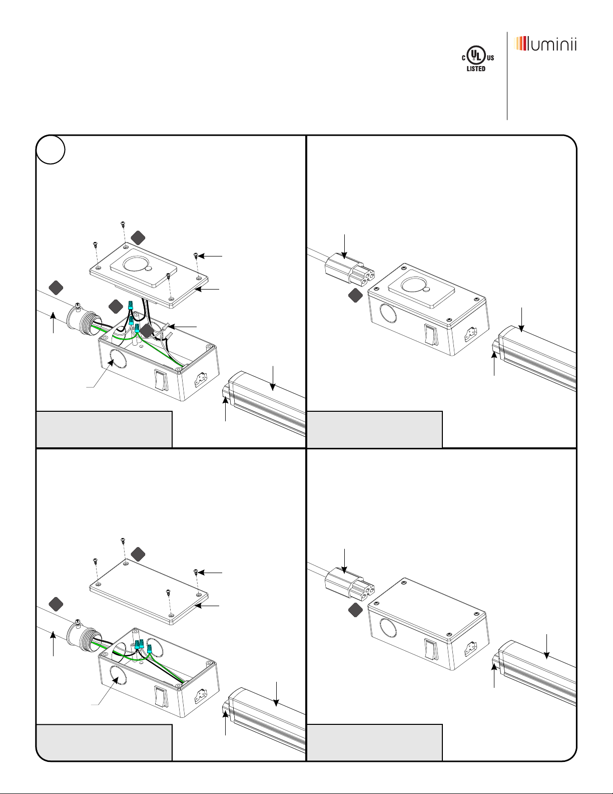
SENSOR/SWITCH INSTALLATION (only follow the directions to your particular model)
occupancy sensor / switch
(splice box)
part # EL-OSSB-WH
on/off switch
(splice box)
part # EL-SB-WH
on/off switch
(used with power cord accessory)
part # EL-SB-PC-WH
4.1 Carefully, remove the 4 screws from the sensor cover.
4.2 Run & connect a 120V AC conduit to the sensor, and secure
(lock nut not shown for clarity in diagram).
4.3 Connect the white (neutral) & black (hot) sensor wires to the
white & black power wires (120VAC). Ground wire in
accordance with local electrical codes. Secure cover back on.
Program sensor reference page 44.4
occupancy sensor / switch
(used with power cord accessory)
part # EL-OSSB-PC-WH
4.1
4.3
4.2
4.4
cover
screw
fixture
conduit
4.1 Connect the power cord (120V AC).
4.1 Carefully, remove the 4 screws from the on/off switch cover.
4.2 Run & connect a 120V AC conduit to the on/off switch and
secure (lock nut not shown for clarity in diagram).
4.3 Connect the white (neutral) & black (hot) wires on/off switch
to the white & black power wires (120VAC). Ground wire in
accordance with local electrical codes. Secure cover back on.
4.1
4.2 cover
screw
fixture joiner
or jumper cable
conduit
DO NOT REMOVE FACTORY
SPLICE CONNECTIONS
4.1
power cord
fixture
fixture joiner
or jumper cable
fixture
fixture joiner
or jumper cable
4.1
power cord
fixture
fixture joiner
or jumper cable
3x1/2"
knockouts
3x1/2"
knockouts
REV0.4 03152019

6264 Oakton St
Morton Grove
IL 60053
T 224.333.6033
F 224.757.7557
www.luminii.com
Easy-Link - Installation Instructions, LED Cabinet Luminaires
Please read all instructions prior to installation and keep for future reference!
*LUMINII RESERVES THE RIGHTS TO CHANGE SPECIFICATION & INSTRUCTION WITHOUT NOTICE
Models EL-
Page 4 of 4
1. Product to be installed by a qualified electrician.
2. Prior to installation ensure power is off at fuse box to prevent electrical shock.
PORTABLE CABINET
LED LUMINAIRE
E475914
SENSOR/SWITCH PROGRAMMING INSTRUCTIONS
sensor/switch
on/off
switch
LED light
indicator
button
technical support
(224) 333-6033
REV0.4 03152019
Table of contents
Other luminii Lantern manuals


