Please read all instructions prior to installation and keep for future reference!
1. Product to be installed by a qualied electrician.
2. Prior to installation ensure power is off at fuse box to prevent electrical shock.
7777 N. Merrimac Ave
Niles, IL 60714
T 224.333.6033
F 224.757.7557
www.luminii.com
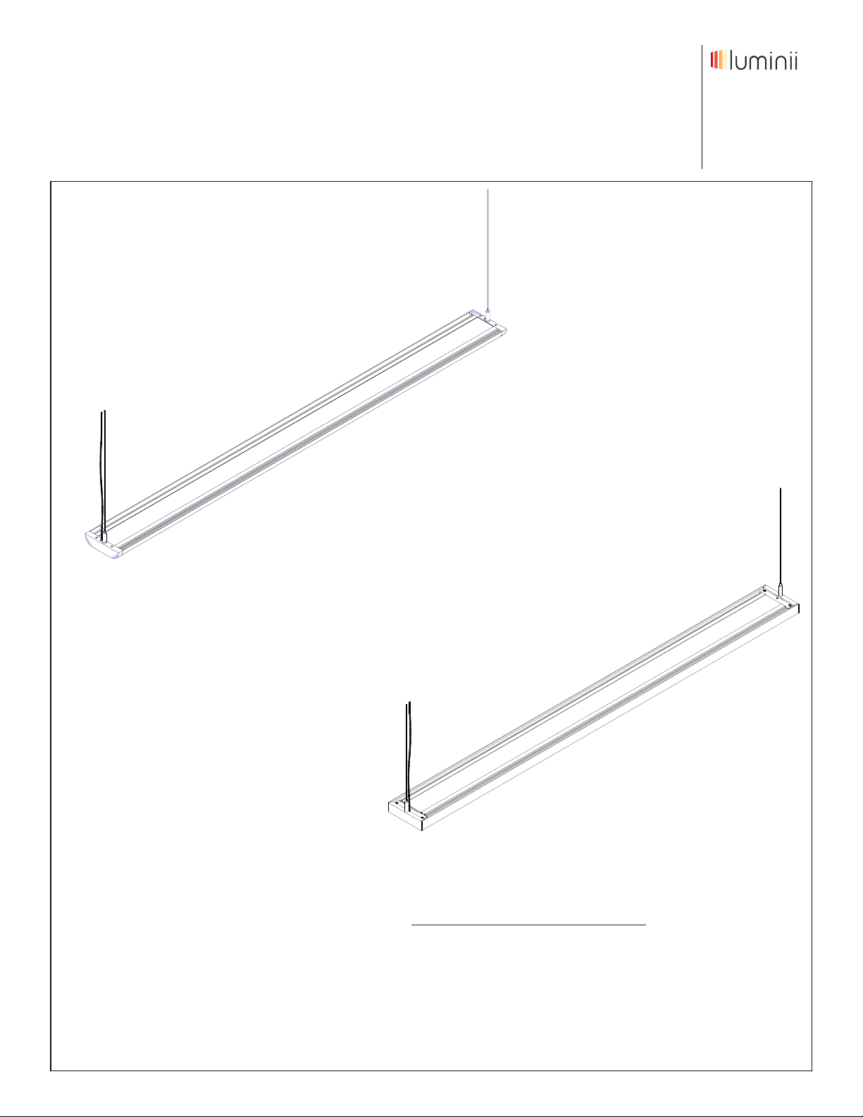
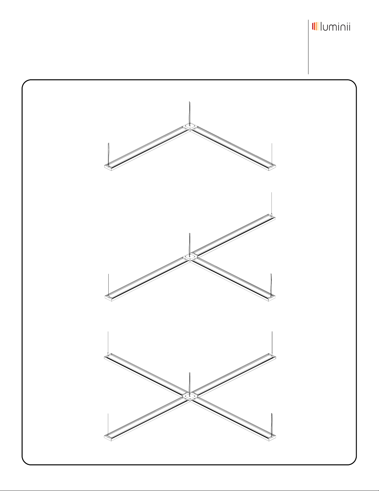
Tavan - Tavan stand-alone installation
REV0.0*LUMINII RESERVES THE RIGHTS TO CHANGE SPECIFICATION & INSTRUCTION WITHOUT NOTICE
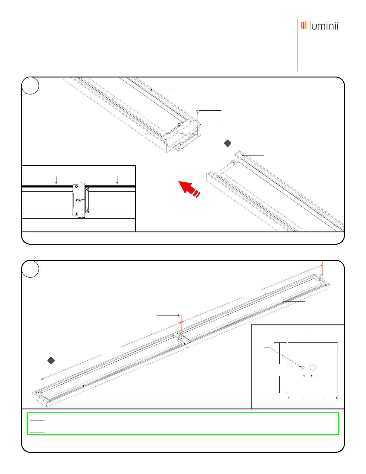
4
4.1 While one person is holding the fixture, the other person can
slide the coaxial cable end through the clear o-rings, thumb
nut, backplate & crossbar assembly.
4.2 Refer to the wiring diagram on page 12 and make all necessary
connections.
junction box
backplate
crossbar
assembly
fixture
power wire
4.1
Note: Prior to wiring the desired fixture height must be
determined to cut off any un-necessary wire.
thumb nut
-4.2
strain
relief
coaxial
cable
4.1
o-ring
3Prior to installing fixture to power, coaxial cable
must be prepared to go inside crossbar assembly.
If this step if skipped coaxial cable metal sleeve
will tangle up.
1 - while holding the coaxial cable end.
2 - Pull back about an 1-1/2" of the
metal sleeve to expose the wires.
metal sleeve wires
3 - Cut off 1-1/2" of the wires.
4 - Pull forward the metal sleeve and
twist to make a firmer single wire.
Models TAV-XX-XX
Note: Prior to installation all wires must be present in
junction box. Junction box must be located within 96” from
the power cable on the fixture. Reference page 12 for wiring
diagrams.
Note: More than one person is recommended for this
installation.
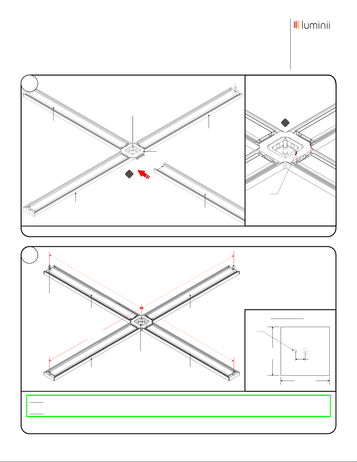
1
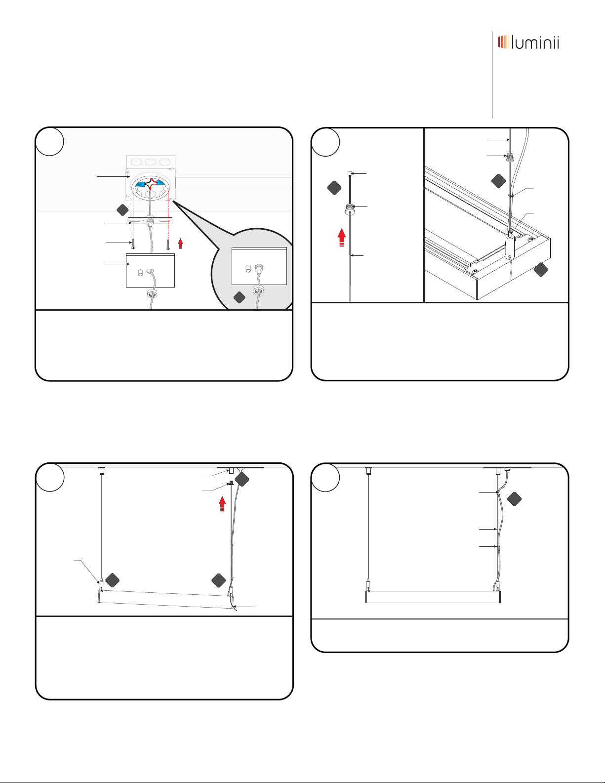
1.1 For stand-alone fixture, align one standoff hub to the junction
box & measure the distance from standoff hub to the other hub.
Then mark this location to the ceiling. Use canopy detail to
slighting off center standoff hub.
canopy detail
4-3/8"
4-3/8"
7/8"
standoff
cap
standoff
location
marks
anchor
2.1 On the marked location(s), make a hole using a 13/64" drill
bit.
2.2 Insert the anchor into the hole and push completely in.
2.3 Insert wood screw through cap & washer and then tighten to
secure into the anchors.
ceiling
drill
13/64"
drill bit
2.1
2.3
2.3
hole
2.2
2
wood screw
cap
spacer
1.1
standoff hub
Tavan
measure
Page 2 of 12
+