Luna 6415 User manual

Setup Guide │Luna 6415

Luna 6415
Luna 6415 Setup Guide
Page i
Many regions prohibit the disposal of WEEE (Waste Electrical
and Electronic Equipment) in the normal waste stream, to
comply with the Restriction of Hazardous Substances (RoHS)
released into the environment. Please contact your local waste
authority for instructions on proper recycling of the electronic
product(s) described in this User Guide.
Luna 6415:
Luna 6415 Setup Guide
© 2019
Luna Innovations Inc.
3155 State Street
Blacksburg, VA 24060
Phone: (866) 586-2682
Fax: (540) 961-5191
E-mail: solu[email protected]m
Web: www.lunainc.com

Luna 6415
Luna 6415 Setup Guide
Page ii
Table of Contents
1 Safety...................................................................................................................................... 3
2 Technical Support................................................................................................................... 4
Mail................................................................................................................................... 4
Phone............................................................................................................................... 4
E-mail............................................................................................................................... 4
3 System Overview.................................................................................................................... 5
Luna 6415 Hardware Configuration.................................................................................. 5
4 What you get with the Luna 6415............................................................................................ 5
A Closer Look at the Luna 6415 ....................................................................................... 7
Front Panel ................................................................................................................ 7
Rear Panel................................................................................................................. 8
Air Vents.................................................................................................................... 8
5 Hardware Setup...................................................................................................................... 9
Power on Sequence................................................................................................... 9
6 Software Setup ......................................................................................................................10
Reflection Mode...............................................................................................................10
Transmission Mode.........................................................................................................12
7 Maintenance and Cleaning.....................................................................................................13
Optical Connector Cleaning Materials..............................................................................13
Cleaning Optical Connectors...........................................................................................14
Cleaning Optical Bulkhead Connections..........................................................................15
Cleaning the Air Filter......................................................................................................16
Cleaning the Case...........................................................................................................17
Replacing Fuses..............................................................................................................17

Luna 6415
Luna 6415 Setup Guide
Page 3
1Safety
The advisory words Danger, Warning and Caution used in this manual identify the level of
hazard that may be encountered by the user.
•DANGER means if the danger is not avoided, it will cause death or serious injury.
•WARNING means if the warning is not heeded, it can cause death or serious injury.
•CAUTION means if the precaution is not taken, it may cause minor or moderate injury.
Warning
The protection provided by the equipment may be impaired if the equipment is used
in a manner not specified by the manufacturer, resulting in serious injury or death.
The power cord is the main electrical disconnect for this equipment. If it is necessary
to ensure no power to the unit, remove the power cord.
The use of controls, adjustments, performance, or procedures other than those
specified herein may result in hazardous laser radiation exposure and one or more
safety protections may be impaired or rendered ineffective.
Attention
La protection fournie par l'équipement peut être compromise si l'équipement est
utilisé d'une manière non spécifiée par le fabricant, entraînant des blessures graves
ou la mort.
Le cordon d'alimentation est le principal disjoncteur électrique de cet équipement. S'il
est nécessaire de ne pas mettre l'appareil hors tension, retirez le cordon
d'alimentation.
L'utilisation de commandes, d'ajustements, de performances ou de procédures
autres que celles spécifiées ici peut entraîner une exposition dangereuse au
rayonnement laser et une ou plusieurs protections de sécurité peuvent être altérées
ou rendues inefficaces.

Luna 6415
Luna 6415 Setup Guide
Page 4
2Technical Support
If you have concerns with or questions about the information contained in this document,
contact our technical support staff using one of the following methods:
Mail
Luna Innovations Inc.
3155 State Street
Blacksburg, VA 24060
Phone
Main Phone: (540) 961-5190
Toll-Free Support: 1.866.LUNA OVA (866.586.2682)
E-mail
solutions@lunainc.com
www.lunainc.com

Luna 6415
Luna 6415 Setup Guide
Page 5
3System Overview
The Luna 6415 provides users with the ability to make high resolution insertion loss and
return loss measurements of optical devices in both reflection and transmission. These
measurements can be viewed in both the delay and spectral domains for improved visibility
in characterizing and screening optical components and networks.
Luna 6415 Hardware Configuration
The flexibility of the reflection or transmission measurement modes allows you to design and
execute tests that perfectly fit your needs. First, it can be set up to measure an optical
device in reflection, meaning the measurement data will consist of all of the light that was
reflected from the device under test and back to the instrument. Secondly, it can be set up to
measure in transmission, meaning that the measurement data will consist of all of the light
that passes through the device under test and then back into the instrument.
4What you get with the Luna 6415
The Luna 6415 is shipped with everything needed to conduct strain and temperature
measurements,including the measurementinstrument and all supporting hardware,
software, documentation,and cables. Read and follow all assembly and startup instructions
before attempting to operate the Luna 6415.
The following components are shipped with each Luna 6415:
Luna 6415 Instrument
One power cord for the Luna 6415
Flash drive containing the user guide and
recovery software

Luna 6415
Luna 6415 Setup Guide
Page 7
A Closer Look at the Luna 6415
Front Panel
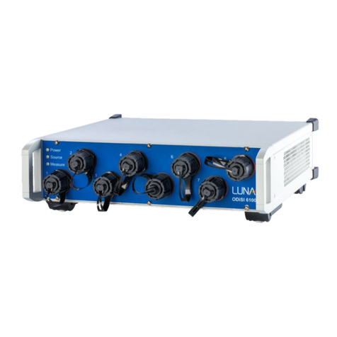
The front panel of the Luna 6415 contains the two optical connectors, as well as three LED
system status indicators.
•Power Lit while the system is powered on
•Source Lit while front panel optical connectors are energized
•Measure Lit while the system is making measurements
Eight optical connectors are located on the front panel of the system. In order to keep the
optical connections clean, it is important to keep dust covers attached while connections are
not in use. Refer to the maintenance information section of this guide for instructions.
Figure 4-1 –Luna 6415 Front Panel

Luna 6415
Luna 6415 Setup Guide
Page 8
Rear Panel
The rear panel of the system contains all of the electrical connections to the system.
Power Entry Module
BNC Triggers (three input and one output)
USB 3.1 Gen I Type B Port
Figure 4-2 –Luna 6415 Panel
Air Vents
Air vents are located on both the sides and rear of the Luna 6415. These vents should
remain unobstructed whenever the system is powered on.
Figure 4-3 - Luna 6415 Air Vents

Luna 6415
Luna 6415 Setup Guide
Page 9
5Hardware Setup
1. Remove all of the Luna 6415 components from the packaging and verify that no
components are damaged or missing (see components list).
2. For best performance, place the unit on a stable surface capable of supporting the
entire weight of the unit. This surface must be clear from any objects that may
reduce the airflow into and out of the fan ducts at the side and rear of the unit.
3. Clean the duplex FC-APC connectors of the device to be tested using the provided
Cletop connector cleaner (see Maintenance section).
4. Unpack and set up the laptop according to the manufacturer’s instructions.
5. Connect the Luna 6415 to the laptop using the USB 3.1 Gen I cable.
6. Attach the power cords to the laptop and Luna 6415.
ATTENTION: Luna requires the use of surge protected and grounded outlets
with the Luna 6415.
Power on Sequence
1. Turn on the Luna 6415 using the power switch on the rear panel.
2. Turn on the laptop.
Note: The Luna 6415 can be restarted without restarting the laptop.

Luna 6415
Luna 6415 Setup Guide
Page 10
6Software Setup
This section provides a short introduction to the main displays in the Luna 6415 software. For
complete instructions on how to start and configure the application, refer to the Luna 6415
User’s Guide, which can be accessed from the Help menu on the Luna 6415 software.
Reflection Mode
When the Luna 6415 software is started, the system will initialize and then launch the
hardware in reflection mode. When the “Measure” button is pressed, a measurement will be
made and will be displayed to the screen.
Figure 6-1 Reflection measurement of a fiber array
It is possible to view this data in different ways using the three plot types presented as tabs
at the top of the plot.
•The “Delay Plot” shows the reflected light as a function of optical time of flight
(generally shown in meters).
•The “Spectral Plot” allows you to see the spectral amplitude response from a subset
of the delay data.
•The “Events” tab displays insertion loss and return loss measurements for any fiber
events detected within the delay data.

Luna 6415
Luna 6415 Setup Guide
Page 11
Figure 6-2 Spectral amplitude response plot showing the spectral amplitude of a single FBG
Figure 6-3 Event tab showing found events and their associated insertion and return losses
Note: It is important to disconnect any devices from the transmission port on the Luna 6415
when using the reflection measurement mode.

Luna 6415
Luna 6415 Setup Guide
Page 12
Transmission Mode
The 6415 can be swapped to transmission mode using the dropdown menu located in the
upper left corner of the screen. The system will configure itself for transmission
measurements and then you will be able to use the same three plot types to interpret the
transmission data.
While in transmission mode, the delay plot shows the amount of transmitted light as a
function of time of flight delay (shown in meters). For any single optical path, there should be
one clear peak, located at the path length of the device being measured. The spectral plot
and event plots work in the same manner as in when in the reflection mode.
Figure 6-4 Transmission measurement of an optical network containing a gas absorption cell.

Luna 6415
Luna 6415 Setup Guide
Page 13
7Maintenance and Cleaning
Optical Connector Cleaning Materials
It is extremely important to clean connectors before attaching optical fibers to the Luna 6415
for testing. Failure to do so may result in noisy data or damaged equipment. Optical fiber
connectors on cables should be cleaned before every connection to the Luna 6415. The
bulkhead connectors on the front panel should be cleaned frequently, roughly once every 25
connections.
The cleaning supplies used with the Luna 6415 are:
•CLETOP connector cleaner –P/N F1-6270
•CLETOP connector cleaner replacement reel –P/N F1-6271
•Cletop 2.5mm Stick (5/package) –P/N F10400
These supplies can be ordered from:
FIS Incorporated
161 Clear Road
Oriskany, NY 13424
Web: www.fiberinstrumentsales.com
E-mail: info@fiberinstrumentsales.com
Important: Use only cleaners approved for use with fiber optic bulkheads and fiber
connectors. Do not use any type of cleaning fluid, cotton swabs, or cloths. Using
unapproved cleaning tools or fluids may result in erroneous or noisy data, or may damage
the fibers and Luna 6415 components.
The optical fiber connector cleaner is used for cleaning connectors:
Figure 7-1 - Connector Cleaner
Cletop sticks are used for cleaning the Luna 6415 bulkhead connectors:

Luna 6415
Luna 6415 Setup Guide
Page 14
Figure 7-2 –Cletop 2.5mm Sticks
Cleaning Optical Connectors
1. Expose the cleaning tape by pushing down the cover release lever.
Figure 7-3 - Exposing the Cleaning Tape

Luna 6415
Luna 6415 Setup Guide
Page 15
1. Hold the fiber connector perpendicular to the cleaner tape surface
2. Swipe the tip of the connector down the first cleaning strip, then swipe on the second
strip.
Figure 7-4 - Cleaning the Connector on the Tape
3. Close the cleaning tape cover before swiping another connector. This advances the
cleaning tape.
Cleaning Optical Bulkhead Connections
Important: The bulkhead should be cleaned approximately every 25 connections. Dirty
connections can lead to connector damage and poor system performance.
1. Turn off the Luna 6415.
2. Make sure that no devices are connected to the Luna 6415.
3. Open the protective cover on the front panel.
4. Gently insert one of the supplied cleaning sticks, as shown below.
5. Twist the stick in one direction and then remove.
Sticks should be discarded after a single use.
Figure 7-5 - Cleaning Optical Bulkhead Connections

Luna 6415
Luna 6415 Setup Guide
Page 16
Cleaning the Air Filter
The left side of the system contains an air filter intended to limit dust buildup within the
chassis. This filter should be cleaned or replaced yearly or as soon as dust buildup is visible
on the filter foam.
1. Ensure that the system is powered down and unplugged.
2. Remove the four screws on the side panel of the system using a #1 Phillips head
screw driver.
Figure 7-6 - Cleaning Air Filter: Remove Screws
3. Remove the side panel to expose the air filter.
Figure 7-7 - Cleaning Air Filter: Remove Filter
4. Remove the air filter and clean with running water. Allow the filter to dry before
reassembly.
5. Insert the air filter back into the space between the top and bottom panels.
6. Replace the side panel and secure using four screws.

Luna 6415
Luna 6415 Setup Guide
Page 17
Cleaning the Case
1. Clean the case by wiping it with a soft cloth dampened with water or a mild, non-
abrasive cleaning fluid such as window cleaner.
Warning
Do not spray any fluid directly on case surfaces. It may seep into the interior of the case and
damage components.
Replacing Fuses
The fuse drawer is located on the power module of the instrument on the back panel.
Warning
To avoid the risk of serious injury or death, ensure that the power cord is disconnected from
the instrument when checking or replacing fuses.
1. Disconnect the instrument power cord.
2. Place the blade of a screwdriver or similar tool in the slot at the bottom of the fuse
drawer, then gently pry the drawer out of the power module.
Figure 7-8 - Remove Fuse Drawer

Luna 6415
Luna 6415 Setup Guide
Page 18
3. Replace fuses with Bussmann AGC-2 type 2A @ 250VAC 1 ¼” x ¼” fast acting (FA)
fuses, rated FS01008.
Figure 7-9 - Insert New Fuses
4. Push the drawer back into the power module until it snaps into place.
5. Reconnect the power cord.
Table of contents
Other Luna Measuring Instrument manuals
Popular Measuring Instrument manuals by other brands

Ametek
Ametek Land SDS installation guide

GHM
GHM GREISINGER G 1500 Compact manual

Milkotester
Milkotester MASTER MINI User information

JENCO
JENCO VisionPlus pH 618 Operation manual

Craind Impianti
Craind Impianti KPO Installation, operation and maintenance manual

Ross
Ross MB-651 Installation and cabling guide

Sper scientific
Sper scientific 850051 quick start guide

TESA
TESA TESA-hite 400 instruction manual

Red Seal Measurement
Red Seal Measurement Datamate 2200 operating & maintenance manual

Kingfisher
Kingfisher KI 2600 Series Operation and maintenance guide

cape cod
cape cod Marine Barometer Installation and operation manual

Bender
Bender LINETRAXX RCM410R-1 manual