Table of Contents
1 Safety .........................................................................................................................................................4
2 Technical Support ......................................................................................................................................5
Mail .....................................................................................................................................................5
Phone ..................................................................................................................................................5
E-mail ..................................................................................................................................................5
3 Hardware and Physical Setup ....................................................................................................................6
Starting the System.............................................................................................................................6
Shutting the System Down..................................................................................................................6
Charging the System ...........................................................................................................................6
4 User Interface.............................................................................................................................................7
UI Layout Overview.............................................................................................................................7
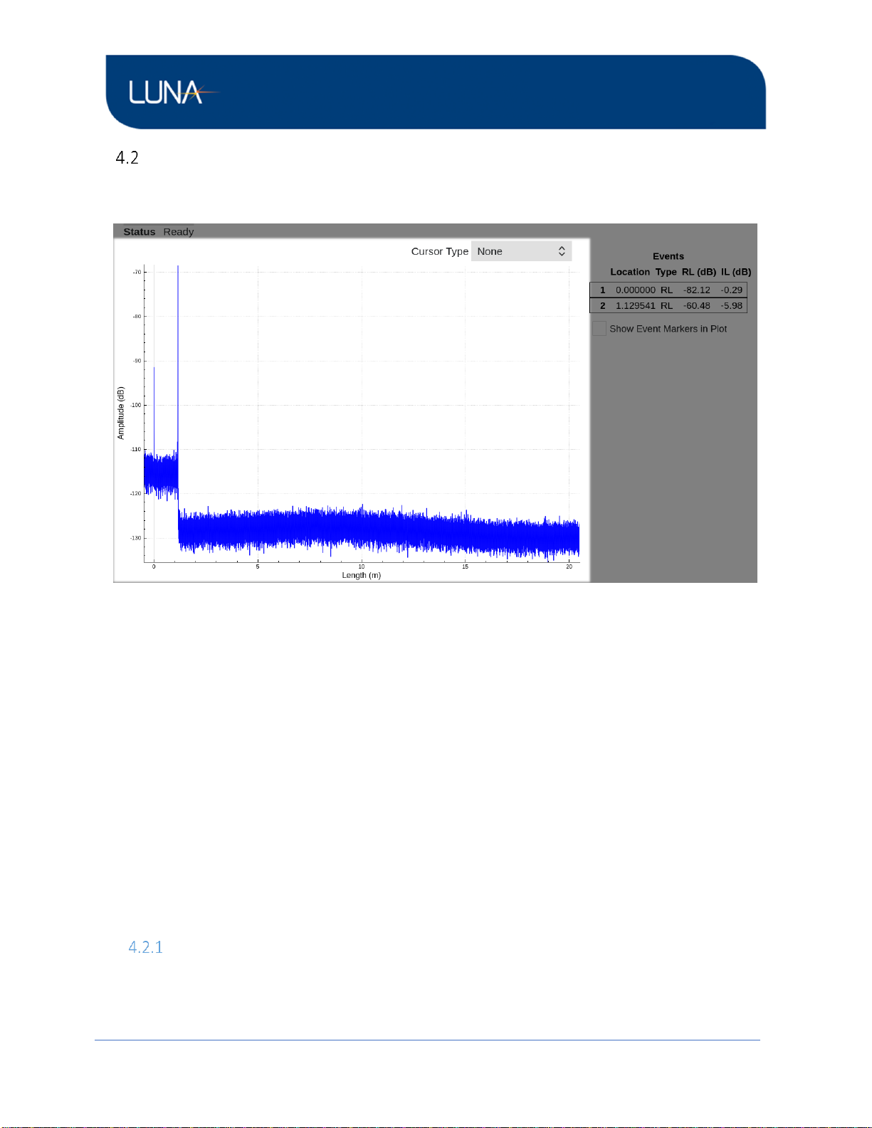
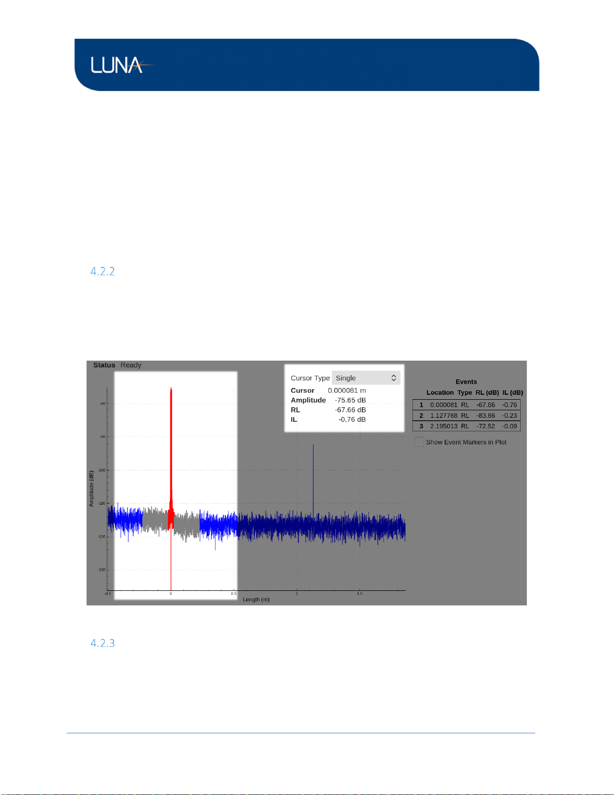
Delay Plot............................................................................................................................................8
Plot Navigation.............................................................................................................................8
Single Cursor ................................................................................................................................9
Vertical Cursor..............................................................................................................................9
Horizontal Cursors......................................................................................................................11
Event Table........................................................................................................................................12
Events.........................................................................................................................................12
Turn Event Table Display On/Off ...............................................................................................13
Event Marks in the Delay Plot....................................................................................................13
Measurement Control and Information ...........................................................................................15
Overview....................................................................................................................................15
Settings and Tools......................................................................................................................15
Measurement Tab...............................................................................................................16
System Tab..........................................................................................................................17
About Tab............................................................................................................................17
File Operations...........................................................................................................................18
Save File ..............................................................................................................................19
Load File ..............................................................................................................................20
Export File ...........................................................................................................................21