LUNATONE 24035465 User manual

© 2017/01/16, Lunatone Industrielle Elektronik GmbH DALI Tou hpanel
DALI Touchpanel
Manual
Control Device
Multifun tional DALI ontrol devi e
with flexible layout
Art. Nr. 24035465
Art.Nr. 24035465-AL

© 2017/01/16, Lunatone Industrielle Elektronik GmbH DALI Tou hpanel
DALI Touchpanel
Control Module
Content
1. Fun tion ........................................................................................................................................... 3
1.1 6-Button Layout / 7-Button Layout – Default-Settings....................................................... 3
1.2 Tunable White Layout ......................................................................................................... 5
1.3 Colour Layout ...................................................................................................................... 6
2. Configuration via DALI-Co kpit Software ........................................................................................ 7
2.1 Configuration of DALI Tou h for Firmwareversion below 4.8 ............................................. 7
2.2 Configuation of DALI Tou h with firmware version =4.8) .................................................. 8
3. Installation ..................................................................................................................................... 14
4. Appli ation Examples .................................................................................................................... 14
5. Appendix A: RGBW or CW-WW for 3 Groups ................................................................................ 15
6. Appendix B: Typi al Colour S ene Values for RGB (Colour) and RGBW Layout ............................ 16
7. Appendix C: Print template ........................................................................................................... 17

3
DALI Tou hpanel, Manual © 2017/01/16, Lunatone Industrielle Elektronik GmbH
1. Function
The DALI-Tou hpanel is a multifun tional input devi e for the ontrol of DALI lighting systems.
The layout of the input devi e an be hanged easily by inserting another layout design and hanging
the fun tion with the help of the DALI-Co kpit. Hen e the devi e offers high flexibility with respe t to
the desired appli ation. The following printed layout- ards are in luded in delivery:
6-Button Layout
7-Button Layout
Tunable White Layout
Color Layout
Ea h layout offers a default- onfiguration for ontrolling the DALI- ir uit immediately out of the box.
The effe tive range is broad ast per default.
For swit hing between layouts and making hanges on the onfiguration the DALI-Co kpit software
tool is available at the Lunatone website.
1.1 6-Button Layout / 7-Button Layout – Default-Settings
The design support s s ene re alls as well as dimming the effe tive range (default=broad ast).

4
DALI Tou hpanel, Manual © 2017/01/16, Lunatone Industrielle Elektronik GmbH
The 7-Button Layout is supported from firmware version 3.1 and higher.
Scene buttons:
Go To S ene 0-2
Dim buttons
:
Up and Down
Off
:
Swit h
Finder
-
L D:
Red led for identifi ation
and finding panel in the
dark.
Led On/Off via long press
Scene buttons:
Go To S ene 0-3
On/Off
:
Swit h
Dim buttons
:
Up and Down
Finder
-
L D:
Red led for
identifi ation and
finding panel in the
dark.
Led On/Off via long
press

5
DALI Tou hpanel, Manual © 2017/01/16, Lunatone Industrielle Elektronik GmbH
1.2 Tunable W ite Layout
The tunable white layout is used for swit hing, dimming and adjusting the olour temperature of
DT8-DALI ballasts with tunable white luminaires (DALI DT8, Mode T ). The effe tive range an be
defined via the DALI-Co kpit (Default=Broad ast)
The tunable white layout is supported from firmware version 2.7 and higher.
On/Off
:
Swit h
Finder
-
L D:
Red led for
identifi ation and
finding panel in the
dark.
Led On/Off via long
Dimming Wheel
Sends DAP ommands
depending on position
Tunable White
Warmer
Tunable White
Cooler

6
DALI Tou hpanel, Manual © 2017/01/16, Lunatone Industrielle Elektronik GmbH
1.3 Colour Layout
The Colour Layout is used for olour ontrol in DALI lighting systems. The olour wheel is divided in
16 s enes. When pressing on the olour wheel the orresponding s ene is re alled for the defined
effe tive range.
Hint
:
The correct scene values have to be stored in the ballasts to ensure that the
correct colours are recalled (see attachment B).
Due to the use of s enes the method an be used for different olour wheels as well as for olour
temperature wheels. The method is working with DT8 ontrol gear as well as with systems at whi h
for ea h olour another ontrol gear is used. The design an be easily adapted for other olours by
hanging the inserted slide.
Colour layout supported from firmware version 3.0 and higher
Colour Wheel
Sele t Colour, the
orresponding s ene is
re alled
On/Off
:
Swit h
Dim buttons
:
Up and Down
Finder
-
L D:
Red led for
identifi ation and
finding panel in the
dark.
Led On/Off via long
Goto
Scene 0
Goto
Scene 1
Goto
Scene 2
Goto
Scene 7
Goto
Scene 8
Goto
Scene 15

7
DALI Tou hpanel, Manual © 2017/01/16, Lunatone Industrielle Elektronik GmbH
2. Configuration via DALI-Cockpit Software
The options of setup depend on the firmware version. Up from firmware version 4.8 the user an
reate layouts by his own, i.e. arranging buttons and assigning fun tions. In older firmware version
the standard layouts an be set up. For onfiguring the devi es the DALI-Co kpit software tool and a
DALI USB interfa e are required.
2.1 Configuration of DALI Touc for Firmwareversion below 4.8
With the help of the DALI-Co kpit tool the a tive layout an be sele ted and the fun tion an be
onfigured. For the predefined layouts only the effe tive range an be set. For Colour and Tunable
White effe tive range and fading an be onfigured.
For the 6- and 7-Button layout ustomized types are available at whi h the fun tion of ea h button
an be onfigured individually (see s reenshot below).
In the most upper dropdown-menu the layout an be sele ted. The firmware-version of the devi e is
shown, hen e you have information about the supported layouts.
firmware version
Selected button
effective range
ON/OFF
-
Command
Dire t Ar Cmd
or Cmd
Dim
-
Mode and
Fading

8
DALI Tou hpanel, Manual © 2017/01/16, Lunatone Industrielle Elektronik GmbH
For ea h Button effe tive range, ON/OFF-Command and Dim-Mode an be onfigured.
Parameter Dim Mode:
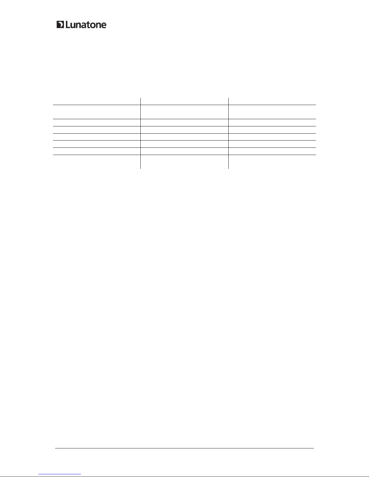
Dim-Mode Short Press Long Press
Toggle ON/OFF Toggles between ON and OFF
Command
Dim Up Only ignored Swit h On if required, Dim Up
Dim Up and ON for Short Press On-Cmd Swit h On if required, Dim Up
Dim Down Only ignored Dim Down
Dim Down and OFF for Short Press Off-Cmd Dim Down
Toggle UP/DOWN ignored Alternating Dim Up/Down
Toggle UP/DOWN and ON/OFF for
Shortpress
Alternating ON- and OFF-Cmd Alternating Dim Up/Down
Example1:
•Effe tive Range: Group G2
•Dim Mode: toggle ON/OFF
•ON/OFF-Cmd: On – GoTo S ene 1, Off – GoTo S ene 1
On ea h press the ommand l GOTO SCENE 1 is sent to group 2.
Example 2:
•Effe tive Range: short addressA03
•Dim Mode: ToggleUp/Down and On/Off for Short Press
•ON/OFF-Cmd: On-Re all Max, Off-Off
On short press alternating on/off using mds RECALL MAX and OFF. On long press alternating dim up
and down. This way it is possible to swit h on/off and dim A03 by one button only.
2.2 Configuation of DALI Touc wit firmware version =4.8)
The onfiguration site is divided in several tabs. For ea h layout and for the general settings tabs are
available.
The menu on the left provides general fun tions: display of the existing layouts, reating new layouts,
deleting existing layout, adding pi s for layouts et . Furthermore the alibration algorithm of the
tou h panel an be started.
On the top of ea h site general devi e information is shown (manufa turer, arti le name, arti le
number, serial number, firmware version et .)

9
DALI Tou hpanel, Manual © 2017/01/16, Lunatone Industrielle Elektronik GmbH
General Settings:
Df
General Settings:
Power-Up: Behaviour of the devi e after power up
TouchPanel-L D and Beeper: De-/a tivate Led and Beeper of the panel
Create New Layout:
With „Add New Layout“ a new layout an be generated . As new layout either a standard layout, an
empty layout or a opy of an already existing layout or a previous exported layout an be hosen. For
ea h new layout a new tab appears (maximum 4). Only one an be used as urrently a tive layout.
Device Info:
Type, Manufa turer …
Firmwareversion,
Update
Add New Layout:
Standard layout
Empty layout
Copy of layout
Import
l
ayout
General Settings:
PowerUp behaviour
Tou hpanel LED
Tou hpanel Beeper

10
DALI Tou hpanel, Manual © 2017/01/16, Lunatone Industrielle Elektronik GmbH
Layout Settings:
In the layout tab several options for onfiguration are available. The layout an be deleted and a pi
an be assigned. This is useful when oordinates of the buttons are defined. The areas of the buttons
an be displayed in the as well by using the he kbox “Show button hints”.
If a standard layout has been sele ted the buttons and ba kground pi are already predefined, but
an be edited by the user.
Beside of adding and deleting layouts, layouts an be exported and the profile an then be imported
for other devi es. Hen e the time intensive generation of a layout has to be done only on e and an
be opied easily to other devi es with the Export/Import feature
The layout that has to be used has to be a tivated using the “Use For Panel“ he kbox.
Buttons:
Ea h layout an onsist of up to 12 buttons. Ea h button is defined by its oordinates (respe tively its
enter and width and height). The values are in % of the omplete layout size (0/0 top left, 100/100
bottom right)
If „Show button hints“ is a tivated all buttons are displayed in the layout overview. The a tive button
is highlighted.

11
DALI Tou hpanel, Manual © 2017/01/16, Lunatone Industrielle Elektronik GmbH
Buttons may overlap, in this ase the button with the highest number is sele ted (in the example
below -> button 7 overrules button 6 in the area of button 7)
For ea h button a fun tion an be defined. Therefore effe tive range, buttonfun tion and DALI
Commands have to be defined.
Up to three destination addresses an be sele ted. The defined ommands are sent to all three
destination addresses.
0/0
100/100
Display
buttons
Add/Delete
Button
Tabs
for
buttons
Coordinates
of Button
DALI
-
Fun
c
tion:
Effe tive Range,
Fun tion, Dali
Cmd

12
DALI Tou hpanel, Manual © 2017/01/16, Lunatone Industrielle Elektronik GmbH
Configuration of the button function:
Definition:
Button Duration
Definition min max
short 40 ms 400 ms
long >400 ms
button-
function
key press release after
short press
long press repeat remarks
0 - - - - -
1 CmdX - - - sends CmdX on key press
2 CmdX - CmdY - sends CmdX on key press
sends CmdY after long press delay
3 CmdX - CmdY CmdY sends CmdX on key press
sends CmdY with 200ms repetition after long
press delay
4 CmdX /
CmdY toggle
- - - sends CmdX and CmdY alternating on key press
5 CmdX /
CmdY toggle
- - - CmdX/Y depending on bus status
6 - CmdX / CmdY
toggle
ON and
STEPUP
UP / DOWN CmdX/Y depending on bus status, UP/DOWN
alternating, ON AND STEPUP, if bus state is OFF
before UP
7 CmdX - - - Swit h , CmdX on Press, CmdY on Release
8 CmdX /
CmdY toggle
- - - Changeover swit h. CmdX/CmdY dependent on
bus status, CmdY/CmdX on Release
9 CmdX - - - Stair ase ontrol. CmdY is sent after a
programmable delay.
10 - CmdX CmdY CmdY CmdX after short press, CmdY for repeat
11 CmdX - - CmdY CmdX with repeat; repeats CmdY without long
press delay
16 DAP ir le
17 S ene ir le
18 CCT ir le
19 RGB ir le
25 Address Sele tion - Instead of all 3 destination
addresses the a tive address an be sele ted (the
sele tion is valid for ea h button on the layout).
26 Finder LED toggle
Hin
t
:
The
ommands are sent
to all effe tive ranges assigned to the button. The address
sele tion ma ro an be used to sele t one of them or to swit h between the destination
addresses.

13
DALI Tou hpanel, Manual © 2017/01/16, Lunatone Industrielle Elektronik GmbH
Configuration of CmdX/CmdY
CmdX and CmdY are ommands or ommand lists that are exe uted as result on the swit hing a tion.
These are:
•DALI ommands
•Predefined ma ros ( ommand lists)
•Customized ma ros
DALI-commands:
Command
Number Command Name Function
- DIRECT ARC POWER dire t ar power level in %
0 OFF Light off
1 UP Dim up (fade-rate)
2 DOWN Dim down (fade-rate)
3 STEP UP In reases light level by one in rement
4 STEP DOWN de reases light level by one in rement
5 RECALL MAX Re alls max level
6 RECALL MIN Re alls min level
7
STEP DOWN AND
OFF de rease light level by one in rement, if already at min level turn off
8 ON AND STEP UP
Swit h to minimum if off, in any other ase in rease light level by one
in rement
10
GOTO LAST ACTIVE
LEVEL (DALI 2) DALI2 ommand: swit h to last a tive level
16-31 GO TO SCENE Re all s ene 0-15
Macros:
Nr Macro (memory) Function
M1 Go Home
(2 Byte)
The light dims to 0 with predefined fade time, at the end a new fade time
is set
M2 Sequential S enes
(3Byte) Swit h to another s ene with ea h button press, s ene list an be defined
M3 Dynami S enes
(9 Byte)
Dynami sequen es of up to 4 s enes, fade time and delay an be defined,
stops with next button press
M4 DALI-Reset
(1 Byte) Sends DALI-Reset ommand (as option the address an be deleted, too)
M5 User Defined Cmd-List
(5 Bytes for ea h md)
User defined ommand list
M6 3x Cooler (DT8)
(0 Byte) a tivates DT8 and sends 3x STEP COOLER
M7 3x Warmer (DT8)
(0 Byte) a tivates DT8 and sends 3x STEP WARMER
Hin
t
:
The memor
y for ma ros is limit
ed
(236
-
16*
number of buttons
)
a
nd
must not
ex eeded ( he k memory of ea h ma ro in ma ro table)

14
DALI Tou hpanel, Manual © 2017/01/16, Lunatone Industrielle Elektronik GmbH
3. Installation
The DALI-Tou hpanel is onne ted dire tly to the DALI-line. It is supplied by the DALI-line dire tly
(typi al urrent onsumption 4mA). The onne tion to the DALI-line is polarity free.
The DALI-Tou hpanel an be mounted on a ba k box. Conne ting wire ross se tion should range
from 1,0mm
2
to 2,5mm
2
.
The DALI-Tou hpanel supports multi-master operation, several modules an be onne ted to the
same DALI-system.
The DALI-Tou hpanel has no DALI-address.
4. Application Examples
typi al stru ture s ene and group ontrol

15
DALI Tou hpanel, Manual © 2017/01/16, Lunatone Industrielle Elektronik GmbH
Typi al stru ture olour and olour temperature ontrol
5. Appendix A: RGBW or CW-WW for 3 Groups
In these spe ial layouts the fun tionality of the olour layout is iused. Press on the olour wheels
re alls the orresponding s ene. The buttons 1-3 an be used to hange the effe tive range.
The layout with address sele tion is supported and the profile an be loaded. The layout ard is not
in luded in delivery.
gr
oup selection

16
DALI Tou hpanel, Manual © 2017/01/16, Lunatone Industrielle Elektronik GmbH
Example:
•default effe tive range: broad ast
•effe tive range button 1-3: G0, G1, G2
With these settings the olour ontrol of 3 groups an be realized using one tou hpanel only.
Appli ation: tunable white ontrol of 3 groups using one tou h panel
6. Appendix B: Typical Colour Scene Values for RGB (Colour) and
RGBW Layout
For making the olour wheel layouts work, the s ene values of the ontrol gear have to be set
orre tly.
RGB:
for
RGB
devices
RGBW: f
or
RGBW
-
devi
ces
,
layout card not included
in delivery

17
DALI Tou hpanel, Manual © 2017/01/16, Lunatone Industrielle Elektronik GmbH
RGB (s ene ballast settings for the RGB layout, default s ene values for Lunatone RGB dimmer)
DT8-scene values Single channel devices (100% brightness)
Szene R G B R G B
0 211 0 42 83% 0% 17%
1 169 0 84 67% 0% 33%
2 127 0 127 50% 0% 50%
3 84 0 169 33% 0% 67%
4 42 0 211 17% 0% 83%
5 0 0 254 0% 0% 100%
6 0 50 203 0% 20% 80%
7 0 101 152 0% 40% 60%
8 0 152 101 0% 60% 40%
9 0 203 50 0% 80% 20%
10 0 254 0 0% 100% 0%
11 50 203 0 20% 80% 0%
12 101 152 0 40% 60% 0%
13 152 101 0 60% 40% 0%
14 203 50 0 80% 20% 0%
15 254 0 0 100% 0% 0%
RGBW (layout ard not in luded in delivery, default s ene values of Lunatone RGBW dimmers, the
differen e to RGB dimmers is marked in red):
DT8-Szenenwerte Single channel devices (100% brightness
Szene R G B W R G B W
0 211 0 42 0 83% 0% 17% 0%
1 169 0 84 0 67% 0% 33% 0%
2 127 0 127 0 50% 0% 50% 0%
3 84 0 169 0 33% 0% 67% 0%
4 42 0 211 0 17% 0% 83% 0%
5 0 0 254 0 0% 0% 100% 0%
6 0 50 203 0 0% 20% 80% 0%
7 0 101 152 0 0% 40% 60% 0%
8 0 152 101 0 0% 60% 40% 0%
9 0 203 50 0 0% 80% 20% 0%
10 0 254 0 0 0% 100% 0% 0%
11 0 127 0 127 0% 50% 0% 50%
12 0 0 0 254 40% 60% 0% 100%
13 152 101 0 0 60% 40% 0% 0%
14 203 50 0 0 80% 20% 0% 0%
15 254 0 0 0 100% 0% 0% 0%
7. Appendix C: Print template


This manual suits for next models
2
Table of contents
Other LUNATONE Control Panel manuals
Popular Control Panel manuals by other brands

Beijer Electronics
Beijer Electronics T15B installation manual

Johnson Controls
Johnson Controls IFC-3030 Operation manual

urmet domus
urmet domus 1061/004 Installation and programming manual

ADEMCO
ADEMCO Galaxy 16 Engineer's manual

Satel
Satel CA-10 Installer manual

SALUPO
SALUPO STAR-DELTA SQ720.00 Instruction and installation manual

Riedel
Riedel CCP1116 quick guide

olympia electronics
olympia electronics BS-316 Installation & operation manual

Bosch
Bosch B9512G quick start guide

Jupiter Avionics
Jupiter Avionics JCP3-070 Installation and operating manual

Snow Switch
Snow Switch GF PRO installation manual

Johnson Controls
Johnson Controls IFC-200 Wiring Manual