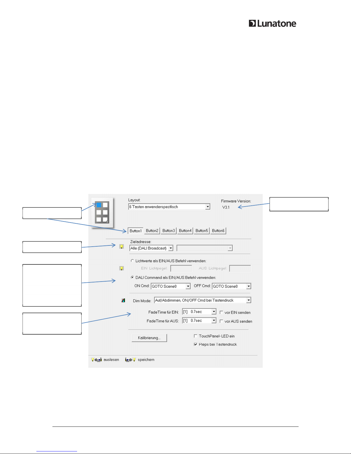
LUNATONE DALI 24035465 User manual

© 2014, Lunatone Industrielle Elektronik GmbH DALI Touch anel
DALI Touchpanel
Manual
Control Device
Multifunctional DALI control device
with flexible layout
Art. Nr. 24035465

© 2014, Lunatone Industrielle Elektronik GmbH DALI Touch anel
DALI Touchpanel
Control Module
Content
1. Function ........................................................................................................................................... 3
1.1 6-Button Layout / 7-Button Layout – Default-Settings....................................................... 3
1.2 6- und 7-Button Layout with user defined buttons ............................................................. 5
1.3 Tunable White Layout ......................................................................................................... 5
1.4 Colour Layout ...................................................................................................................... 6
2. Configuration via DALI-Cock it Software ........................................................................................ 7
3. Installation ....................................................................................................................................... 8
4. A lication Exam les ...................................................................................................................... 9
5. A endix A: RGBW or CW-WW for 3 Grou s – cusotmized Layout ............................................... 9
6. A endix B: Ty ical Colour Scene Values for Colour Wheels of RGB (Colour) and RGBW (Colour
3Button) Layout ..................................................................................................................................... 10

DALI Touch anel, Manual © 2014, Lunatone Industrielle Elektronik GmbH
1. Function
The DALI-Touch anel is a multifunctional in ut device for the control of DALI lighting systems.
The layout of the in ut device can be changed easily by inserting another layout design and changing
the function with the hel of the DALI-Cock it. Hence the device offers high flexibility with res ect to
the desired a lication. The following rinted layout-cards are included in delivery:
6-Button Layout
7-Button Layout
Tunable White Layout
Color Layout
Each layout offers a default-configuration for controlling the DALI-circuit immediately out of the box.
The effective range is broadcast er default.
For switching between layouts and making changes on the configuration the DALI-Cock it software
tool is available at the Lunatone website.
The effective range can be changed for each layout. At the 6-Button and 7-Button layout for each
button the function can be configured as well.
1.1 6-Button Layout / 7-Button Layout – Default-Settings
Ex lanation of the 6- and 7-Button default-layout.
The standard configuration su orts scene recalls as well as switching and dimming commands sent
to a definable effective range (broadcast er default, can be changed via DALI-Cock it software tool).

DALI Touch anel, Manual © 2014, Lunatone Industrielle Elektronik GmbH
The 7-Button Layout is su orted from firmware version 3.1 and higher.
S
c
ene
buttons
:
Go To Scene 0-2
Dim buttons
:
U and Down
Off
:
Switch
Finder
-
L D
:
Red led for identification
and finding anel in the
dark.
Led On/Off via long ress
Scene buttons:
Go To Scene 0-3
On/Off
:
Switch
Dim buttons
:
U and Down
Finder
-
L D:
Red led for
identification and
finding anel in the
dark.
Led On/Off via long
ress

DALI Touch anel, Manual © 2014, Lunatone Industrielle Elektronik GmbH
1.2 6- und 7-Button Layout with use defined buttons
The button ositions are the same like in the default configuration. The function of a button can be
selected. The design of the layout can be changed easily by using another insertion slide.
For each button the effective range and the button function can be configured. The rogrammable
buttons can be configured as follows:
•Switch On/Off a single control gear, grou s or broadcast
•Dimming of a single control gear, grou s or broadcast
•Recall Scenes
For details lease check the cha ter “Configuration via DALI Cock it Software”.
1.3 Tunable White Layout
The tunable white layout is used for switching, dimming and adjusting the colour tem erature of
DT8-DALI ballasts with tunable white luminaires (DALI DT8, Mode Tc). The effective range can be
defined via the DALI-Cock it (Default=Broadcast)
The tunable white layout is su orted from firmware version 2.7 and higher.
On/Off
:
Switch
Finder
-
L D:
Red led for
identification and
finding anel in the
dark.
Led On/Off via long
Dim
ming Wheel
Sends DAP commands
de ending on osition
Tunable White
War,er
Tunable White
Cooler

DALI Touch anel, Manual © 2014, Lunatone Industrielle Elektronik GmbH
1.4 Colou Layout
The Colour Layout is used for colour control in DALI lighting systems. The colour wheel is divided in
16 scenes. When ressing on the colour wheel the corres onding scene is recalled for the defined
effective range. This means that the colour values have to be set in the scenes of the control gear
belonging to the effective range. Due to the use of scenes the method can be used for different
colour wheels as well as for colour tem erature wheels. The method is working with DT8 control
gear as well as with systems at which for each colour another control gear is used. The design can be
easily ada ted for other colours by changing the inserted slide.
Colour layout su orted from firmware version 3.0 and higher
Colour Wheel
Select Colour, the
corres ing scene is
recalled
On/Off
:
Switch
Dim buttons
:
U and Down
Finder
-
L D:
Red led for
identification and
finding anel in the
dark.
Led On/Off via long
Goto
Scene 0
Goto
Scene 1
Goto
Scene 2
Goto
Scene 7
Goto
Scene 8
Goto
Scene 15

DALI Touch anel, Manual © 2014, Lunatone Industrielle Elektronik GmbH
2. Configu ation via DALI-Cockpit Softwa e
With the hel of the DALI-Cock it tool the active layout can be selected and the function can be
configured. To ensure that all available functions are su orted we recommend you to load the last
recent version of the DALI-Cock it software tool down from the Lunatone website. For the
connecting your PC to the DALI-line a DALI-USB interface is required. With the hel of the DALI
Cock it the DALI Circuit can be addressed and configured.
For the redefined layouts only the effective range can be set. For Colour and Tunable White
effective range and fading can be configured.
User defined layouts can be defined more individually (see screenshot below)
In the most u er dro down-menu the layout can be selected. The firmware-version of the device is
shown, hence you have information about the su orted layouts.
For each Button effective range, ON/OFF-Command and Dim-Mode can be configured.
f
irmware
v
ersion
Selected button
effective range
ON/OFF
-
Command
Direct Arc Cmd
or Cmd
Dim
-
M
ode
a
nd
Fading

DALI Touch anel, Manual © 2014, Lunatone Industrielle Elektronik GmbH
Parameter Dim Mode:
Dim-Mode Short Press Long Press
Toggle ON/OFF Toggles between ON and OFF
Command
Dim U Only ignored Switch On if required, Dim U
Dim U and ON for Short Press On-Cmd Switch On if required, Dim U
Dim Down Only ignored Dim Down
Dim Down and OFF for Short Press Off-Cmd Dim Down
Toggle UP/DOWN ignored Alternating Dim U /Down
Toggle UP/DOWN and ON/OFF for
Short ress
Alternating ON- and OFF-Cmd Alternating Dim U /Down
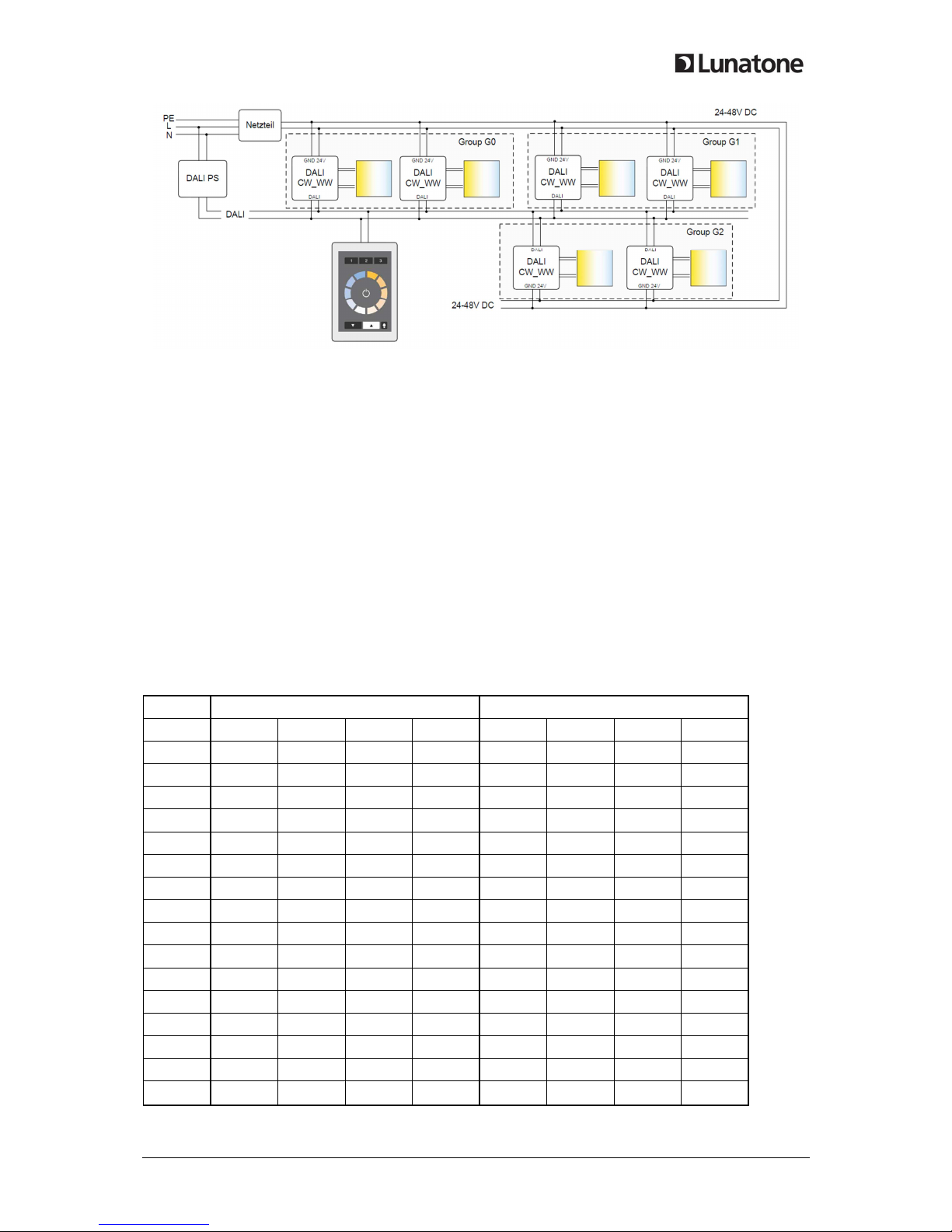
Exam le1:
•Effective Range: Grou G2
•Dim Mode: toggle ON/OFF
•ON/OFF-Cmd: On – GoTo Scene 1, Off – GoTo Scene 1
On each ress the command l GOTO SCENE 1 is sent to grou 2.
Exam le 2:
•Effective Range: short addressA03
•Dim Mode: ToggleU /Down and On/Off for Short Press
•ON/OFF-Cmd: On-Recall Max, Off-Off
On short ress alternating on/off using cmds RECALL MAX and OFF. On long ress alternating dim u
and down. This way it is ossible to switch on/off and dim A03 by one button only.
3. Installation
The DALI-Touch anel is connected directly to the DALI-line. It is su lied by the DALI-line directly
(ty ical current consum tion 4mA). The connection to the DALI-line is olarity free.
The DALI-Touch anel can be mounted on a back box. Connecting wire cross section should range
from 1,0mm
2
to 2,5mm
2
.
The DALI-Touch anel su orts multi-master o eration, several modules can be connected to the
same DALI-system.
The DALI-Touch anel has no DALI-address.

DALI Touch anel, Manual © 2014, Lunatone Industrielle Elektronik GmbH
4. Application Examples
Scene/Grou -Control
Colour/TunableWhite Control
5. Appendix A: RGBW o CW-WW fo 3 G oups – customized layout
In these customized
1
layouts the functionality of the colour layout is im lemented. Press on the
colour wheels recalls the corres onding scene. The buttons 1-3 can be used to change the effective
range. After 5 seconds without ress action the effective range is switched back to default.
Exam le:
•default effective range: broadcast
•effective range button 1-3: G0, G1, G2
With these settings the colour control of 3 grou s can be realized using one touch anel only.
1
customized layouts on request
group selection

DALI Touch anel, Manual © 2014, Lunatone Industrielle Elektronik GmbH
A lication: tunable white control of 3 grou s using one touch anel
6. Appendix B: Typical Colou Scene Values fo Colou Wheels of
RGB (Colou ) and RGBW (Colou 3Button) Layout
For making the colour wheel layouts work, the scene values of the control gear have to be set
correctly. Please find attached ty ical values ( lease note that the colour is de endent on the
luminaire itself).
RGBW 4-Channel control gear (colour layout with address selection):
DT8-Scene Value Single Channels (100% brightness)
Scene R G B W R G B W
0 0 0 0 254 0% 0% 0% 100%
1 84 42 0 127 33% 17% 0% 50%
2 127 63 0 63 50% 25% 0% 25%
3 170 73 0 12 67% 29% 0% 5%
4 210 44 0 0 83% 17% 0% 0%
5 254 0 0 0 100% 0% 0% 0%
6 220 0 26 0 87% 0% 10% 0%
7 182 0 71 0 72% 0% 28% 0%
8 0 0 254 0 0% 0% 100% 0%
9 0 20 235 0 0% 8% 93% 0%
10 0 70 180 0 0% 28% 71% 0%
11 0 120 120 15 0% 47% 47% 6%
12 0 250 10 0 0% 98% 4% 0%
13 0 254 0 0 0% 100% 0% 0%
14 70 170 0 0 28% 67% 0% 0%
15 112 112 0 30 44% 44% 0% 12%

DALI Touch anel, Manual © 2014, Lunatone Industrielle Elektronik GmbH
RGB 3-Channel (colour layout without white):
DT8-Scene Value Single Channels (100% brightness)
Scene R G B R G B
0 211 0 42 83% 0% 17%
1 169 0 84 67% 0% 33%
2 127 0 127 50% 0% 50%
3 84 0 169 33% 0% 67%
4 42 0 211 17% 0% 83%
5 0 0 254 0% 0% 100%
6 0 50 203 0% 20% 80%
7 0 101 152 0% 40% 60%
8 0 152 101 0% 60% 40%
9 0 203 50 0% 80% 20%
10 0 254 0 0% 100% 0%
11 50 203 0 20% 80% 0%
12 101 152 0 40% 60% 0%
13 152 101 0 60% 40% 0%
14 203 50 0 80% 20% 0%
15 254 0 0 100% 0% 0%
Table of contents