© Lundell Plastics Corporation · 400 W Market St. · Odebolt, IA 51458 · P 712.668.2400 · TF 877.367.7659 · F 712.668.2402
1317:4
Page 2 of 2
(Do this only after the initial troubleshooting measure of transmitter battery replacement has been completed.) Each
transmitter generates a unique signal,and your receiver unit needs to be able to identify and respond to that signal in
order to operate.The use of a unique signal for each transmitter prevents your receiver from being susceptible to outside
interference, and protects against stray signals causing potentially undesirable operation.Some customers prefer to have
multiple key fob controls for their units.Each FreeFloWireless Remote is capable of handling and responding to multiple
(up to five) key fob transmitters;you simply have to“learn”each individual transmitter to your receiver unit.Additional key
fob controls are available through Lundell Plastics (877) 367-7659.
To complete the“learn”procedure,simply do the following.Power up the unit.When you do so,the LED on the receiver unit
will flash RED four times.This indicates that the unit has received power.There is a magnetically controlled switching circuitry
embedded in the receiver unit.Place a fairly powerful magnet over the receiver“learn”area (see diagram on page 1 for location)
for a brief moment (3 seconds),and then remove it.(Learn magnets are available through Lundell Plastics.) The LED will go to
a constant RED state.Now immediately press any button on the transmitter you are attempting to“learn”.The LED will go to a
GREEN/YELLOW color.This confirms that the receiver has picked up a signal from the transmitter,and subsequently“learned”that
signal.Communication has been established,and it is now ready to function properly.
Should the above procedure not complete successfully, wait until the LED light goes out,and repeat the procedure.If for
any reason you experience a second failure of the“learn”procedure,do the following:place the magnet on the“learn”
area and the LED will go to a constant RED state,leave the magnet in place on the receiver until the LED light goes out
(approximately 10 seconds).This action completely clears the receiver’s memory.It’s akin to reformatting,or freeing up all
of the space on a computer hard drive.Once you have cleared the memory,proceed with the standard“learn”procedure
detailed above for each of the key fob transmitters you wish to use with the device.If,after all of the procedures detailed
above are completed,the unit is still not functioning,check the battery in the transmitter once again.(Occasionally,even
new batteries fail,or are defective from the factory. If you have a voltage meter,confirm that battery voltage is at least 2.7
volts.) If that still does not solve the problem,contact our wireless control customer service at (877) 367-7659
for assistance.
During standard operation,to confirm the receiver is picking up a signal from the transmitter,the receiver will respond to keypad
inputs by illumination of the receiver LED (see diagram on page 1.This system has a triple momentary configuration;the three
outputs (White,Gray and Orange wires) are controlled through operation of the remote. The control button configuration on your
FreeFlo wireless system (01T0TM) is as follows:
Troubleshooting :
About Frequency“Learning”:
“Learning”Instructions :
Operational Parameters :
Visit us online at www.lundellplastics.com to see other innovative products!
INSTRUCTION MANUAL
FreeFlo Wireless Remote
Model 01T0TM - Triple Momentary Output
(cont. from prev. page)
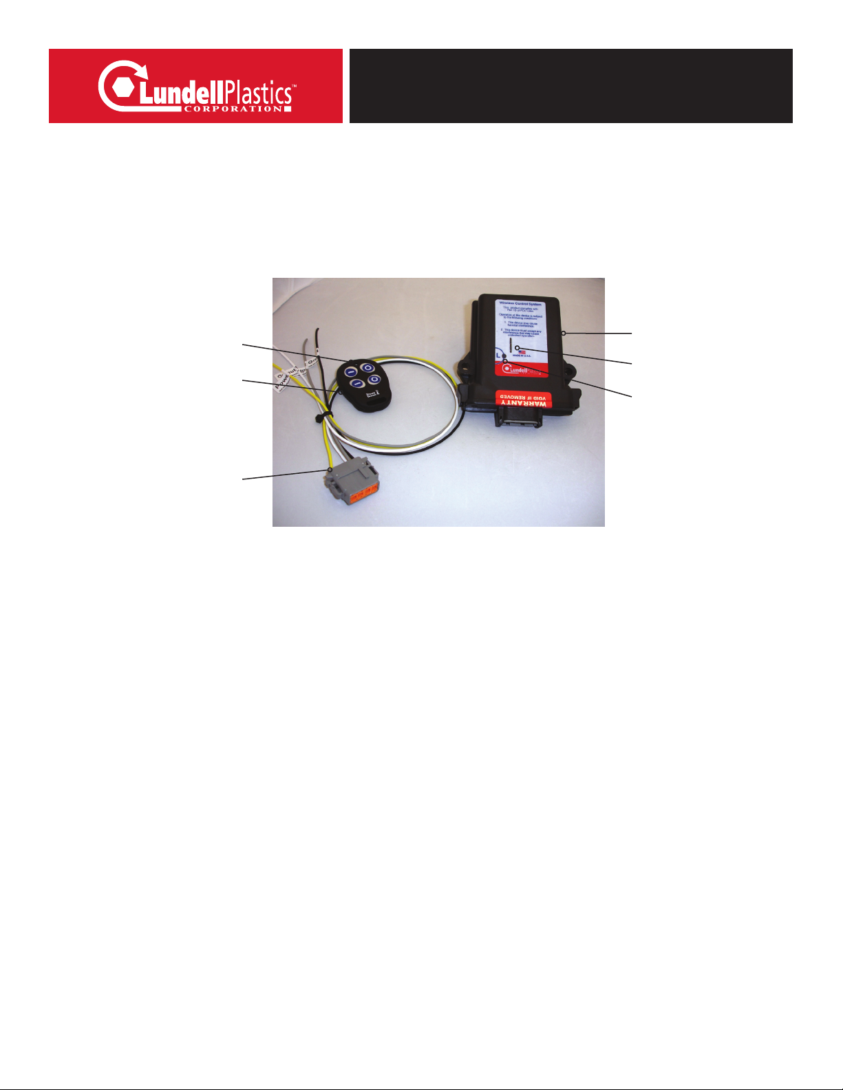
The wiring harness has three wires coming out of the RF receiver unit.The plug
pin-out and wire colors are as follows:
Pin 1 – Yellow - Power Lead (+12V IN)
Pin 3 – Orange - Output (+12V momentary - while button 3 is depressed)
Pin 5 – White - Output (+12V momentary - while button 1 is depressed)
Pin 7 – Black - Ground Lead (connect to ground)
Pin 8 – Gray - Output (+12V momentary - while button 2 is depressed)
Button 1 – On - Momentary
(+12V Momentary)
Gray Wire
Button 3 – On - Momentary
(+12V Momentary)
Orange Wire
Button 1 – On - Momentary
(+12V Momentary)
White Wire
Button 4 – Inactive
IMPORTANT: The receiver is intended for 12 volt input and 7 amp max output.
Exceeding these limits will void any product guarantee and cause damage to the receiver.