Lupus Electronics LUPUSEC-XT2 User manual

XT2 Version 2.14
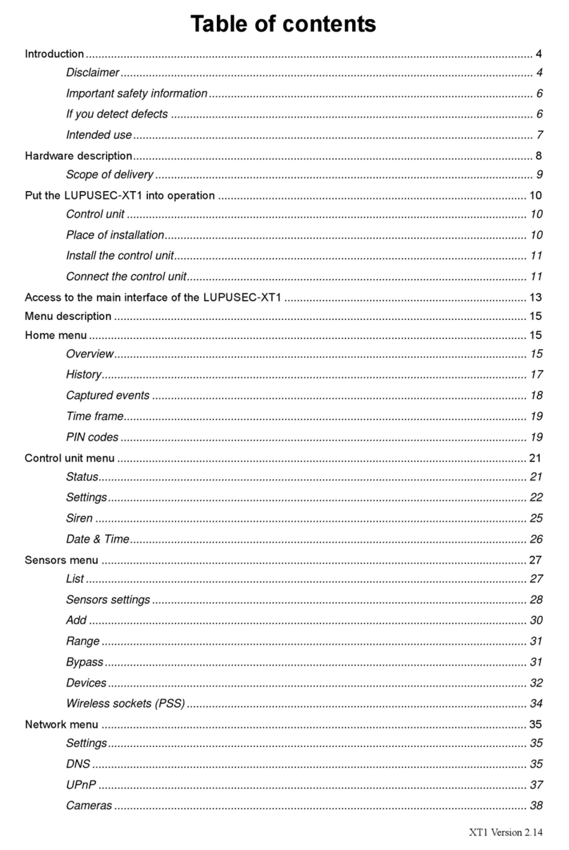
Table of contents
Introduction.............................................................................................................................................. 4
Disclaimer................................................................................................................................... 4
Important safety information....................................................................................................... 6
Detection of defects.................................................................................................................... 7
Designated use........................................................................................................................... 7
Hardware description............................................................................................................................... 8
Scope of delivery........................................................................................................................ 9
Put the LUPUSEC-XT2 into operation .................................................................................................. 10
Control unit ............................................................................................................................... 10
Place of installation................................................................................................................... 10
Install the control unit................................................................................................................ 11
Connect the control unit............................................................................................................ 11
Access to the main interface of the LUPUSEC-XT2 ............................................................................. 13
Change the language of the XT2 interface............................................................................................ 14
Description of menus............................................................................................................................. 15
Home menu ........................................................................................................................................... 15
Overview................................................................................................................................... 15
History....................................................................................................................................... 18
Captured events ....................................................................................................................... 18
PIN codes ................................................................................................................................. 19
Control unit menu .................................................................................................................................. 20
Status........................................................................................................................................ 20
Automation................................................................................................................................ 21
Wireless switches ..................................................................................................................... 23
UPIC (universal IR transmitter)................................................................................................. 24
Sensors menu ....................................................................................................................................... 25
List ............................................................................................................................................ 25
Edit sensor................................................................................................................................ 27
Add............................................................................................................................................ 32
Range ....................................................................................................................................... 32
Devices..................................................................................................................................... 33
Siren.......................................................................................................................................... 36
Network menu ....................................................................................................................................... 38
Settings..................................................................................................................................... 38
DNS .......................................................................................................................................... 38
UPnP......................................................................................................................................... 39
GSM & SMS ............................................................................................................................. 40

2
ENGLISH
Cameras ................................................................................................................................... 44
Settings menu........................................................................................................................................ 46
Contact ID................................................................................................................................. 46
Contact ID syntax .................................................................................................................................. 47
Control unit ............................................................................................................................... 49
Special codes ........................................................................................................................... 55
Report....................................................................................................................................... 56
E-mail........................................................................................................................................ 57
Upload....................................................................................................................................... 59
Language.................................................................................................................................. 60
System menu......................................................................................................................................... 61
Password.................................................................................................................................. 61
Firmware................................................................................................................................... 62
Backup & Restore..................................................................................................................... 63
Log files..................................................................................................................................... 63
Remote access via the internet ............................................................................................................. 65
Create Dynamic DNS account.................................................................................................. 67
Access via your iPhone ............................................................................................................ 72
The user interface of the LUPUSEC-XT2 mobile app (iPhone) ............................................... 74
Access via the LUPUSEC-Android app.................................................................................... 80
Profile list ..................................................................................................................... 81
Main menu ................................................................................................................... 82
Navigation through the app.......................................................................................... 83
Description of sensors and controls ...................................................................................................... 84
Remote keypad KP-01.............................................................................................................. 84
Put keypad into operation............................................................................................ 85
Window / door contact.............................................................................................................. 88
Put the window/door contact into operation................................................................. 89
Wireless indoor siren................................................................................................................ 89
Put the wireless in door siren into operation................................................................ 90
Wireless outdoor siren.............................................................................................................. 92
Put the wireless outdoor siren into operation .............................................................. 92
Smoke detector......................................................................................................................... 96
Put the smoke detector into operation......................................................................... 96
PIR motion detector.................................................................................................................. 98
Put the PIR motion detector into operation.................................................................. 98
Water detector........................................................................................................................ 100
Put the water detector into operation......................................................................... 100
Remote control ....................................................................................................................... 101
Put the remote control into operation ........................................................................ 101
Medical emergency controller................................................................................................. 102

3
ENGLISH
Put the medical emergency controller into operation ................................................ 102
Wireless sockets (PSS).......................................................................................................... 103
Put the wireless sockets into operation ..................................................................... 103
Glass breakage detector......................................................................................................... 105
Put the glass breakage detector into operation......................................................... 105
PIR network camera............................................................................................................... 107
Put the PIR network camera into operation............................................................... 107
Temperature sensor ............................................................................................................... 110
Put the temperature sensor into operation ................................................................ 110
Temperature sensor with display............................................................................................ 111
Put the temperature sensor into operation ................................................................ 111
Wireless relay......................................................................................................................... 113
Put the wireless relay into operation.......................................................................... 113
Magnetic locking device.......................................................................................................... 115
Install the magnetic locking device to the doorframe and put it into operation.......... 116
Mechanical locking device...................................................................................................... 117
Install the mechanical locking device to the doorframe and put it into operation...... 118
Panic button............................................................................................................................ 120
Put the Panic button into operation............................................................................ 120
Wireless repeater.................................................................................................................... 121
Connect the repeater to the control unit .................................................................... 122
CO detector ............................................................................................................................ 124
Put the CO detector into operation:........................................................................... 124
Heat detector .......................................................................................................................... 125
Put the heat detector into operation:.......................................................................... 125
Wireless sensor input ............................................................................................................. 127
Put the wireless sensor input into operation:............................................................. 128
Wireless lock contact.............................................................................................................. 130
Install the wireless lock contact to a door and put it into operation: .......................... 130
In-wall relay with electric meter .............................................................................................. 132
Put the in-wall relay with electric meter into operation .............................................. 132
In-wall relay without electric meter ......................................................................................... 133
Put the in-wall relay without electric meter into operation ......................................... 133
Tag reader .............................................................................................................................. 134
Put the tag reader into operation............................................................................... 136
Dual motion detector............................................................................................................... 138
Put the PIR / microwave motion detector into operation ........................................... 141
Mini indoor siren ..................................................................................................................... 143
Put the mini indoor siren into operation..................................................................... 143
All information subject to change. Errors and omissions excepted.

4
ENGLISH
Introduction
Thank you for purchasing the LUPUSEC-XT2 wireless security system. Before you
start the system, please take the time to read the following safety and installation
information carefully and attentively. It is imperative to comply with these instructions
in order to ensure the safe operation. If you have any further questions, please
contact your local retailer or LUPUS-Electronics directly. Your LUPUSEC-XT2 was
developed and built with state-of-the-art technology and complies with European and
German standards. Declarations of conformity are available on request or for
download at www.lupus-electronics.de.
Please keep this manual safely to be able to answer possible questions in the future.
The manual is an integral part of the product even in case it is resold to a third party.
Disclaimer
All technical details and descriptions in this manual have been written with the
greatest care. However, Lupus-Electronics cannot entirely exclude mistakes in this
manual. Therefore, we do not assume any legal responsibility or liability, which is
result of wrong information in this manual. Descriptions, technical images and
technical data are subject to change according to technical progress without notice.
In addition, LUPUS-Electronics reserves the right to change this product and its
manual without prior notice. We do not assume any guarantee with regard to the
content of this document. We appreciate any comments on mistakes or inaccuracies,
which may help us to improve this product and this manual.
This symbol is intended to attract the user’s attention to the potential risk
of dangerous unprotected voltage inside the housing. This may lead to
an electric shock.
This symbol is intended to attract the user‘s attention to use and
maintenance instructions in the manual and documents enclosed to the
product.

5
ENGLISH
WARNING:
TO MINIMIZE THE RISK OF AN ELECTRIC SHOCK, YOU MUST NOT EXPOSE
THIS PRODUCT TO WET AND MOIST CONDITIONS AT ANY TIME.
All Lupus-Electronics products are lead-free and meet the requirements
stated under the European Directive on the Restriction of Hazardous
Substances (RoHS). This guarantees that the entire production process
and the product itself are free of lead and of all listed hazardous substances.
This product was tested and complies with the regularities for a class of
digital devices stated under FCC part 15. These limits were specified to
provide reasonable protection against harmful exposure when operating
the device in a commercial environment. This product emits and uses
radio energy. It may in addition interfere with other radio communication systems, if it
is not installed or used according to this manual. Using the device in residential areas
may cause disturbances to be possibly remedied at the user’s expense.
If installed properly according to this manual, the product complies with
CE regularities. To avoid the risk of electromagnetic interferences (e.g.
with radios or radio traffic), it is highly recommended to use shielded
cables only.
Conformity:
The declaration of conformity is available at:
LUPUS-Electronics GmbH
Otto-Hahn-Str. 12
D-76829 Landau

6
ENGLISH
Important safety information
Warning
The warranty claim will expire in case of damages resulting from
the non-observance of this manual.
We do not assume any liability for consequential damages.
We do not assume any liability for damages to persons and/or
material whatsoever, which result from improper handling or
noncompliance with the safety instructions. The warranty claim
will expire in such cases!
This wireless alarm system is equipped with a high-quality housing. However, please
observe the following safety regulations:
Never open the control unit housing! This is dangerous and your warranty will
expire immediately.
Connect this product only to the approved voltage according to this manual.
Operate the alarm system only with the provided power supply unit.
The socket must be located in an easily accessible, moisture-proof indoor location.
Handle the alarm system with care, heavy vibration or bumps may damage this
alarm system.
Do not expose the alarm system to direct sunlight or strong heat, e.g. heaters.
To prevent overheating, install the control unit only in the shade and not close to
any heat source, e.g. heater!
Provide for sufficient ventilation of the system. Keep a minimum safety distance of
20 cm (8 inch) on all sides.
Do not install the alarm system close to strong electric power lines or magnetic
fields, as this may impair the transmission quality significantly.
Do not install the alarm system directly on iron or aluminium surfaces without
isolating the foot of the alarm system from the floor, as this may impair the
wireless transmission significantly.
Do not install the alarm system in moist, very cold or very hot environments.
Please observe the maximum humidity and temperature limits.
Persons (including children) with limited physical, sensory, or mental abilities
and/or lacking experience and/or knowledge must not use this product.
Keep children away from the product and other connected electric appliances at all
times. The alarm system includes cables, which may strangle children, and small
parts, which they may swallow. Lay cables expertly so that they are neither bent
nor otherwise damaged. Assemble the alarm system out of children’s reach. Do
not leave packaging materials unattended, they may be dangerous for playing
children.
Use a damp cloth to clean the alarm system’s surface. Afterwards, dry the surface.
Cleaning agents will damage the surface.

7
ENGLISH
Detection of defects
If you notice any kind of defect, disconnect the alarm system from the power supply
and contact your retailer or Lupus-Electronics directly. Any further usage of the
system may lead to fire or electric shock!
Designated use
This alarm system is intended for property security purposes. Install the control unit
indoors only. Any other use than described in this manual is not permitted and will
lead to the expiry of any warranty or guarantee as well as to the exclusion of liability.
The same applies to modifications and retrofitting.
Information on disposal:
Do not dispose of the device with the domestic waste!
This product complies with the EU Directive on waste electrical and electronic
equipment (WEEE) and therefore must not be disposed of with the domestic
waste. Dispose of the device via your local collection point for waste
electronic equipment!
This product contains software programs subject to the GPL free software
license.
This product contains software that was developed by third parties and/or software
subject to the GNU General Public License (GPL) and/or the GNU Lesser General
Public License (LGPL). We will send you the source code of these programs on
request. The GPL and/or LGPL code used and offered in this product is EXCLUSIVE
OF ANY GUARANTEE WHATSOEVER and is subject to the copyright of one or
several authors. For further details, please refer to the GPL and/or LGPL code of this
product and to the terms of usage of GPL and LGPL.
You can read the complete license text at http://www.gnu.org/licenses/gpl-2.0.html.
For the unofficial German translation, please go to
http://www.gnu.de/documents/gpl.de.html

8
ENGLISH
Hardware description
The LUPUSEC-XT2 control unit has three different control LEDs, which inform you
about the control unit’s status.
1. Error LED
Red on = system error (list via Control unit Status XT2 Status)
Off = system in proper state
2. Area 1 LED
Red on = Area 1 in Armed mode (Arm)
Green on = Area 1 in Home mode (Home 1, Home 2, Home 3)
Flashes red = Alarm in Area 1
Flashes red + Area 2 LED flashes green = Control unit in Add sensors mode or
Test range mode
3. Area 2 LED
Red on = Area 2 in Armed mode (Arm)
Green on = Area 2 in Home mode (Home 1, Home 2, Home 3)
Flashes red = alarm in Area 2
Flashes green + Area 1 LED flashes red = Control unit in Add sensors mode or
Range test mode
1
2
3

9
ENGLISH
1. (Mini) SIM card slot
2. Battery on/off switch
3. Power supply connection
4. USB port
5. LAN port
6. Learn button
Scope of delivery
Please check immediately after the delivery of the LUPUSEC-XT2 control unit,
whether the product’s scope of delivery includes the following components:
Alarm system LUPUSEC-XT2
Drilling template including screw set
LAN cable
12 V power supply unit (power consumption: 2.1 Watt in normal state, 5 Watt with
activated internal siren)
If anything is missing, please contact your retailer immediately.
2
3
6
5
1
4

10
ENGLISH
Put the LUPUSEC-XT2 into operation
The following pages describe the installation and start-up of the LUPUSEC-XT2
systematically. To avoid damages to the system, please observe these instructions in
detail and read the manual carefully before you start. For your convenience, you will
find detailed installation videos on the enclosed CD.
Control unit
Take the control unit out of the packaging. Check for possible transportation
damages immediately after the delivery. If you see any damage, please complain to
your local retailer promptly.
Place of installation
The place of installation is crucial for the smooth operation of the system, as all
sensors (door/window contacts, smoke detectors, glass breakage detectors, etc.) are
connected to the control unit wirelessly (868 MHz or 2.4 GHz). Therefore, choose the
place of installation so as to ensure the shortest airline distance between the control
unit and all sensors. A central, open place is a good choice.
Furthermore, make sure that neither metals nor strong magnetic fields interfere with
the radio communication.
Do not install the control unit in the following locations:
Basements
Close to microwaves, ovens, hobs, iron doors, or iron walls
Garages
Cupboards or drawers
Do not place objects in front of the device.
The device is not intended for the operation in space with high temperatures or
humidity (e.g. bathrooms) or excessive dust.
Max. operating temperature and operating humidity:
10°C to +50°C, maximum 75 % relative humidity
Operate the device in a moderate climate only.
Please note and/or ensure:
That this manual might be outdated. For the latest pdf version, go to www.lupus-
electronics.de or contact the Lupus support service.
Always to provide sufficient ventilation.
To leave a safety clearance of 10 cm on all sides.
That no direct heat sources (e.g. air conditioning/heaters) are close to the device,
which may affect the device.
That no direct sunlight hits the device.
That the device is not located close to magnetic fields (e.g. speakers).
Not to place any open fire sources (e.g. candles) on or next to the device.

11
ENGLISH
To avoid the contact with splash or dripping water and aggressive liquids.
That the device is not operated close to water. In particular, never submerge the
device (do not place any objects filled with liquids, e.g. vases or drinks, on or next
to the device).
That no foreign objects enter the device.
That the device is not subject to great temperature fluctuations, as this may cause
humidity to condense and cause electric short circuits.
Not to expose the device to excessive vibrations.
Warning When in doubt do not assemble, install, and wire the system by yourself,
but hire a specialized electrician. Improper and unprofessional execution
of works at the power supply system pose a danger to you and other
persons.
Install the control unit
You can either position the LUPUSEC-XT2 in a central place or mount it to the wall.
For the latter purpose, screws, dowels, and a drilling template are included in the
scope of delivery. To mount the device to wall, remove the rubber nubs from the
bottom of the device.
Connect the control unit
1. Remove the rubber cover from the back and turn the battery switch to ON.
Note:
In case of power failure, the internal battery can supply the control unit with power for
approx. 12 hours.
2. Connect the LAN cable to the control unit and then connect it to your router. Most
routers are equipped with several ports for gadgets.

12
ENGLISH
3. Connect the provided power supply unit to the LUPUSEC-XT2.
The control unit needs about 30 seconds to boot.
4. The Error LED of the control unit lights up and an warning signal sounds every 30
seconds. The cause is that usually no SIM card is inserted upon the first start-up,
which the control unit interprets as a system error. The chapter “Status” describes
how to ignore such errors.

13
ENGLISH
Access to the main interface of the LUPUSEC-XT2
The control unit administration is controlled via a browser-based user interface, which
is built like a web page. On these web page, you can control all system functions of
the XT2, add and edit sensors, arm or disarm the control unit, check for open
windows or doors, and view pictures from your LUPUSNET HD network camera and
recorder (if installed and connected).
To open the main menu of the control unit, proceed as follows:
1. Start the link “LUPUSEC-XT2 network finder” from the CD (or enter the IP address
of the XT2 - if already known - in your browser).
2. Click on “Search”. The control unit should be found. Select the XT2 from the list
with the left mouse button.
3. Click on “Configure Setting”, if you want to change the IP settings of the control
unit. If your network includes a DHCP server, this should not be required.
Otherwise, e.g. in case of a direct connection via a crossover cable or no
router/DHCP server available, you need to assign an IP address to the control unit
manually, which is in the same network as your access device (PC, notebook…).
4. Double-click on the found control unit or alternatively on “Open Web Page”. Your
standard browser opens and the connection to the XT2 is established.

14
ENGLISH
Enter one of the following access data:
User name: admin, password: admin1234
The admin can configure all settings of the XT2, only he can change network settings
and system settings (firmware, backup, factory settings).
User name: expert, password: expert1234
Provides experts with all the required rights. All the important system settings
(add/configure sensors) can be changed. The user can configure neither network nor
system settings.
User name: user, password: user1234
Provides inexperienced user with rights.
Note:
We recommend using Mozilla Firefox for web access to the XT2, which is available
on the provided CD.
After you accessed your control unit once via the IP finder, this method is not
required anymore. You can save the IP address of the control unit e.g. in the list of
favourites or bookmarks of your browser to access the user interface of the control
unit in an easier and quicker way.
Change the language of the XT2 interface
You can change the language of the XT2 interface via System Language. Select
the required language and confirm with OK.

15
ENGLISH
Description of menus
Home menu
Provides you with an overview of important information all in one: overview, history,
PIR camera, and PIN codes.
Overview
The main window of the LUPUSEC-XT2 shows all the important information on the
status of your alarm system. You can see at a glance, whether e.g. a window is open,
an alarm was triggered, a battery runs low, or live pictures from your LUPUSNET HD
camera (not included in scope of delivery).
The main window comprises 10 main sections:
1
2
5
6
7
8
9
10
3
4

16
ENGLISH
1. The main menu
Is the main control unit of the XT2. The selected main menu is always highlighted in
orange. Via the main menu, you navigate to the sub-menus (9) and thus access all
configuration menus of the XT2.
2. Battery status, date, and time:
Shows the battery status of all sensors connected to the system. If the battery of
one or more sensors is low or empty, a red dot is shown. If the battery status of all
sensors is OK, the dot is green.
To the right of the battery status, the current time is shown and below that (if
activated) times of sunrise and sundown of the current day.
3. The sub-menus
You can access the selection of various sub-menus via the main menu (1). The font
colour of the selected sub-menu is orange. The displayed configuration menu
changes with the selection.
4. Firmware version, GSM, logout
Shows the currently installed firmware version. Please note that Lupus Electronics
offers regular updates of firmware version for download in order to implement new
functions or correct mistakes.
GSM: Active means that the XTC identified a SIM card.
By means of the logout, you leave the web interface of the XT2 and log out of the
control unit.
5. The Alarm Status widget
The Alarm Status shows, whether the alarm system is armed/ disarmed or in a
home mode. You can change it by means of the alarm buttons. It also shows an
overview of the most important system messages and events.

17
ENGLISH
oIf the alarm system is set to Arm, it is armed, i.e. each activation of a sensor
causes an alarm.
oUse the Home modes 1-3 to activate specific partial areas. If e.g. a motion
detector is located in the kitchen, which would trigger an alarm when someone
enters the kitchen at night, set the item “Home 1 response” to “No response” in
the settings of the motion detector to deactivate it in this mode.
oIf the alarm system is set to Disarm, it is disarmed and will not trigger any alarm
as a rule. There are exceptions (water, medical emergency, fire alarm…), which
the chapter “Edit sensor” describes in more detail.
oThe two areas to be selected in the upper right corner stand for two separately
controlled partial areas. Thus, you can control e.g. the living room and the office
in one object separately – like two alarm systems.
Note:
You can work with 80 sensors per area, in total up to 160.
You can arm the Home modes out of the Disarm mode only.
6. The Sensor widget
Shows the most important seven sensors connected to the system. Window and door
contacts are listed on top. You can see promptly, whether e.g. a sensor is open,
entirely out of service, detected motions or activated tamper contacts.
7. The Control widget
If you bought PSS sensors (wireless + in-wall relays) for your alarm system, you can
activate, deactivate, and create automations for the connected devices.
8. The Recent Events widget
Shows the last event, system, and contact ID events.
9. The History widget
Shows the last sensor events and system messages.
10. The LUPUS Cameras widget
Shows current images of your LUPUS cameras or recorders. They must have been
configured before via the menu Network Cameras. The PIR network camera can
only take pictures in the Arm mode, but cannot stream live (save battery power).
These screenshots are located in Home PIR camera.

18
ENGLISH
History
The history shows all sensor messages of the connected temperature sensors or
electric meters as well as the system messages. The history lists each system
message, like e.g. armed or disarmed, with date and time.
Shows the recent sensor events, sorted by date, time, sensor name, and event.
Captured events
Shows all recent recordings of motions captured by your PIR cameras, sorted by
zone, picture, and recording date. Click on a recorded picture click to zoom in.

19
ENGLISH
PIN codes
PIN codes are exclusively relevant to the user for controlling the control unit with a
keypad. They enable up to 20 different users (per area) to arm/disarm the system.
Firmware 0.0.2.7M and higher enable controlling both areas with a keypad.
Depending on which area the PIN code belongs to, the respective area is controlled.
User Code
Always consists of four digits. Each PIN code can be assigned only once, even in
different areas.
User name
You can optionally assign the user name.
Expires
You can set a date in the form 2015/12/31 12:00. After this set date/time, the PIN
code is no longer valid. If you leave the field blank, then validity of the code is
unlimited.
Arm/Disarm
This option serves to set the authorization to arm or disarm the control unit with the
respective PIN code.
Report
With this option, you are informed, when the respective PIN code is used.
Delete
Deletes the respective PIN code. To apply changes, click “OK”. If you want to neglect
the last changes, click “Reset”.

20
ENGLISH
Control unit menu
Contains the Status menu to see possible failures of the control unit, the Automation
menu to create automations, the menu for wireless switches (wireless sockets + in-
wall relays) as well as the UPIC control for air conditioning systems.
Status
The menu “XT2 Status” shows the status of the LUPUSEC-XT2.
Zones:
Areas:
To arm or disarm the two areas of the LUPUSEC-XT2 alarm system or to activate the
Home mode.
XT2 Status:
Shows the battery status, the tamper contact status, possible radio interferences with
other transmitters, the DC power supply status, as well as the transmission power.
Transmission power shows the quality of the transmission in the current environment.
The smaller the number, the more optimal are the conditions on location.
XT2 Restart: Reboots the system.
XT2 Error display: A table lists each system error (control unit, sensors,
connections, lacking SIM card). Every new system error triggers a regular audio
alarm. You can disable each of these warnings with “Ignore system error”. If the list
contains a system error that was not ignored, this will be indicated upon arming or
activation of the home mode.
Table of contents
Other Lupus Electronics Security System manuals
Popular Security System manuals by other brands

Fike
Fike TWINFLEX 313-0021 Installation and maintenance instructions

Pambry
Pambry Listen Ear PED-1704-L user manual

Magellan
Magellan MG-6060 Reference and installation manual

Data Aire
Data Aire MINI DATA ALARM PROCESSOR II Operation and maintenance manual

Speaks z wave
Speaks z wave SSA1 instruction manual

Steren
Steren TRS-400 user manual