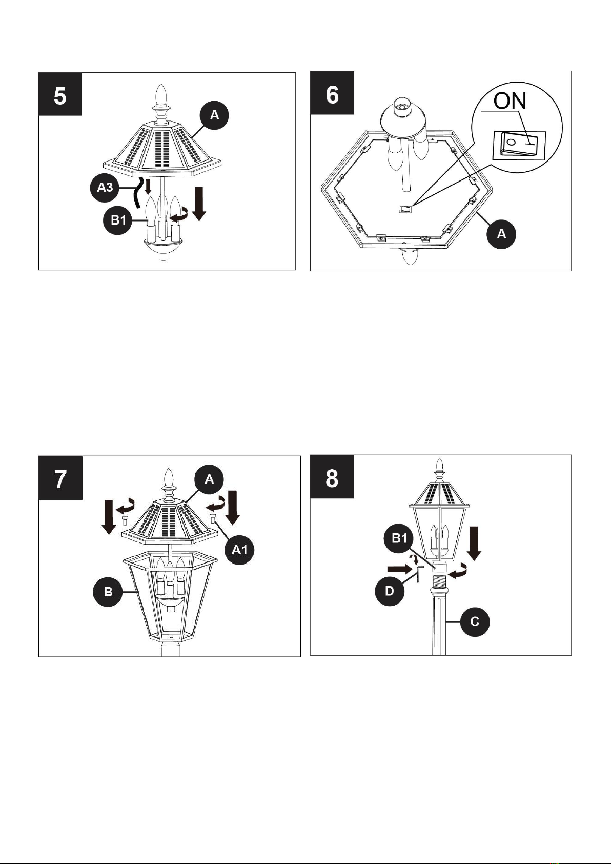
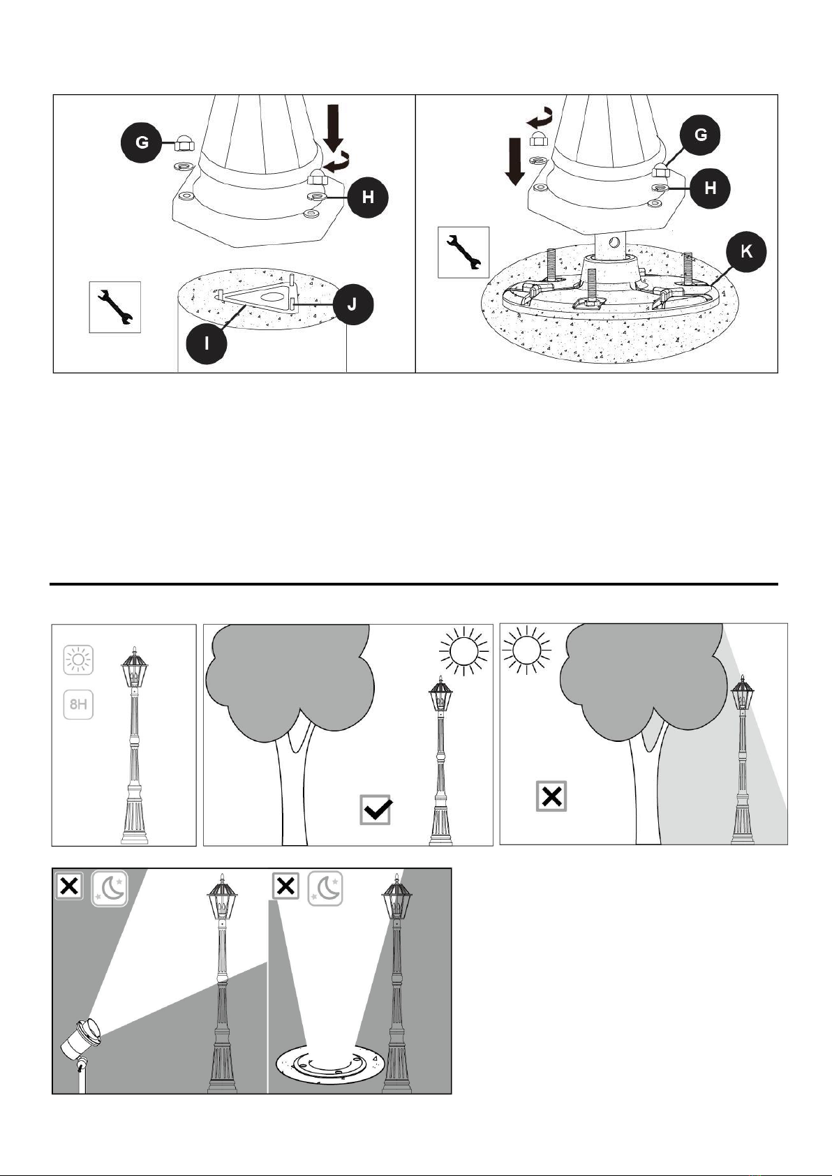
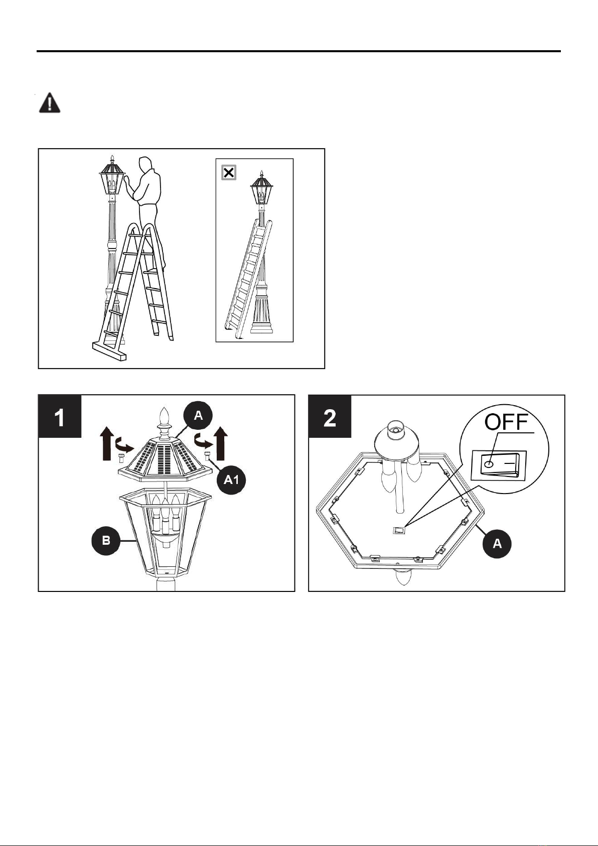
LUTEC 12513LE-SL User manual

1
ASSEMBLY, INSTALLATION, CARE & USE
INSTRUCTIONS
IMPORTANT, RETAIN FOR FUTURE REFERENCE:
READ CAREFULLY
For assistance please contact our customer service hotline Monday-Saturday 8 a.m-6 p.m Pacific Time Zone
Toll Free 1-(877) 714-8669
LUTEC USA CUSTOMER SERVICE
149-B Houston Rd Troutman, NC 28116
E-mail: [email protected]
Website: www.lutec.com
Solar Post Lantern
Owners Manual
Model 12513LE-SL

2
PACKAGE CONTENTS

3
PART
DESCRIPTION
QUANTITY
A
Solar Panel Top
1
A1
Thumbscrew
2
A2
Battery NO. 9700356000
1
A3
Ribbon
1
A4
Battery Cover
1
A5
Battery Cover Screw
1
B
Lamp Head
1
B1
Solar LED Bulb NO. 9700357000
3
B2
Set Screw 1
1
C
Top Pole
1
C1
Set Screw 2
1
D
1/8’’ Allen Wrench
1
E
Middle Pole
1
F
Base
1
F1
Base Screw
3
G
13/32’’ Cap Nut
3
H
13/32’’ Washer
3
I
Concrete Mounting Bracket
1
J
Anchor Bolt
3
K
Ground Base Insert
1
L
Small Ground Stake
3
M
Large Ground Stake
1
N
Turn Rod
1
O
13/32’’ Nut
3
P
13/32’’ x 2 3/16’’ Hex Bolt
3
Q
3/16’’ x 7/8’’ Ground Stake Screw
3
SPECIFICATIONS:
Model: 12513LE-SL
LED Color: 2700K
Lumens: 300LM
Total power: 6W
Battery: Li-ion
Voltage: 7.4V
Battery Capacity: 2200 mAh
Power Source: Monocrystalline Silicon Solar Panel
Light Duration: Up to 10 hours
Measurements: 12 7/32’’ x 10 7/25’’ x 89 3/8’’ (31 x 26.1 x 227 cm)
SAFETY INFORMATION
Please read and understand this entire manual before attempting to assemble, operate or install
the product.
The solar panel “Post Light” requires sunlight to charge the batteries and should be installed in an
WARNING:

4
area with a minimum of 8 hours of direct sun exposure.
Note: Charging conditions differ by time zone locations and affects total hours of light discharge.
PREPARATION
Before beginning to assemble or install lighting fixture, make sure all parts are present. Compare
parts with package contents list and hardware contents list. If any part is missing or damaged, do
not attempt to assemble, install or operate the product.
Estimated Assembly Time: 30-60 minutes.
Tools Required for Assembly: Flathead Screwdriver, Phillips Screwdriver, Pliers, 1/2’’ Wrench,
ladder and hammer.
DETERMINE DESIRED INSTALLATION-PERMANENT CONCRETE PAD OR GROUND STAKE
INSTALLATION: PERMANENT CONCRETE PAD
Thread three J Anchor Bolts into the I Excavate a hole in the groundthat measures
Concrete Mounting Bracket allowing for 2” (5cm) at minimum 10” (26cm) in diameter and has a
above the Mounting Bracket. minimum depth of 5” (12cm).
Fill hole with concrete and insert I and J before
the concrete dries.
Note: The concrete and the concrete mounting bracket I should be at GROUND LEVEL, with
the anchor bolts J 2’’ (5cm) above the ground.

5
INSTALLATION: GROUND STAKE
Install P to K, and tighten with O.
Attach M to K by screwing Q tight with Phillips screwdriver. Then insert N.
Turn ground stake assembly clockwise by using Ninto the dirt until K is tight against the dirt. Insert
L into the grass. You may have to use a hammer to get L into your dirt.
Note: Make sure that the level in M is always in the horizontal position.

6
ASSEMBLY INSTRUCTIONS
Remove the preassembled C1 set screw from C and screw C clockwise onto E. Re-insert C1 set
screw, then tighten with D. Remove the preassembled 3 base screws F1 from F with a Phillips
screwdriver (not included). Save for later use.
Secure E to F with F1. Tighten with a Phillips Remove A1 thumbscrew, then detach A from B.
screwdriver. Take out B1 bulbs from the box.

7
Install B1 light bulbs, and pull off A3 ribbon. Turn on the switch in A.
Attach A to B with A1. Tighten with Carefully screw the lamp head onto C, securing
flathead screwdriver (not included). with the preassembled set screw B1. Tighten
with D.

8
Installation: Concrete Pad Installation: Ground Stake
With the help of another person, place the With the help of another person, place the
assembly over I and J. Secure with G and H. assembly over K. Secure with G and H.
Tighten with a 1/2’’ wrench (not included). Tighten with a 1/2’’ wrench (not included).
CAUTION: Allow the concrete to dry before
installing the pole assembly.
MAXIMIZING SOLAR LIGHT POST PERFORMANCE

9
Charging: Charge in direct sunlight for 8-10 hours.
Location: Choose location with minimum 6-8 hours sunlight. When choosing a spot for your solar
light, ensure that the device is not placed near nighttime light sources such as porch lighting or
street lighting.
Dusk To Dawn: The light will not activate during daylight hours. At sundown the light will go on
automatically and last approximately 6-8 hours
Cleaning solar panels: It is important that dirt and debris is kept off of the solar panel to the greatest
extent possible. A dirty solar panel will not fully charge the battery and thus shorten the battery life.
Battery replacement: Generally speaking, the rechargeable battery should be replaced every two
years in order to maintain the maximum capacity. Please refer to the specs for max charge cycles.
Note: Run times and lighting performance will vary depending upon sunlight and weather
conditions.

10
BATTERY/BULB REPLACEMENT
Replacement batteries and bulbs are available thru LUTEC USA by calling 877-714-8669. The
model number for the battery is 9700356000, the model number for the bulb is 9700357000.
Warning: The supplied LED bulbs have been specially developed for use with the solar post
light model 12513LE-SL and must be replaced with model 9700357000. The use of any other type
bulbs will not function in the fixture.
Remove A1then detach A from B. Turn off the power switch in A.

6
A
A5
A4
3
A
A5
A4
11
Remove the preassembled screw A5 from the battery cover A4 with a Phillips screwdriver (not
included). Then remove the battery cover A4. Remove the old battery A2 and unplug the black
battery cord. If the bulb is broken, remove the broken bulb B1.
Plug new black battery cable into light fixture. Insert new battery into battery compartment by
carefully placing battery cable into the cable storage area under battery. Install new bulb. Attach the
battery cover A4 to A with screw A5 removed in step 3. Tighten with a Phillips Screwdriver (not
included).

12
Turn on the switch in A. Attach A to B with A1. Tighten with flathead screwdriver (not included).
CARE AND MAINTENANCE
To clean and wipe with a damp, non-abrasive cloth.
TROUBLESHOOTING
PROBLEM
POSSIBLE CAUSE
CORRECTIVE ACTION
The light will not go on.
1. Switch OFF.
2. The battery is completely
discharged.
3. DUSK TO DAWN activited.
4. The bulb is loose.
5. Interference from other light
source.
6. The battery is not charged
1. Set to ON.
2. Charge for 6-8H.
3. Check at night.
4. Re-tighten the bulb.
5. Relocate the solar post light.
6. Make sure the solar panel is in
direct sunlight.
The fixture shakes in high
winds.
1. The mounting bracket could
be loose.
2. The insert may be loose.
3. The screws and cap nuts
may be secured incorrectly.
1. Make sure the mounting
bracket screws are tightened.
2. Make sure the insert is
assembled completely and
tightly.
3. Make sure the screws and cap
nuts were secured tightly.
The lights come on during
the daylight.
1. The light may be installed
in a dark location.
1. Relocate to sunny location.

13
3-YEAR LIMITED WARRANTY
If this product fails due to a defect in materials or workmanship within three (3) years (Battery and
bulbs excluded) from the date of purchase, return it along with proof of date of purchase and it will
be replaced with the same or comparable model free of charge.
This warranty is void if damage or defect has resulted from accident, abuse, misuse or faulty repair.
This warranty gives you specific legal rights and you may have other rights that vary from state to
state.
IN NO EVENT WILL LIABILITY EXTEND TO ANY CONSEQUENTIAL, SPECIAL, INCIDENTAL
OR INDIRECT DAMAGES OF ANY KIND ARISING OUT OF THE USE OR MISUSE OF THIS
PRODUCT. SOME STATES DO NOT ALLOW THE EXCLUSION OR LIMITATION OF
INCIDENTAL OR CONSEQUENTIAL DAMAGES SO THE ABOVE EXCLUSION OR LIMITATION
MAY NOT APPLY TO YOU.

14
INSTRUCTIONS D’ASSEMBLAGE, D’INSTALLATION,
D’ENTRETIEN & D’UTILISATION
IMPORTANT, CONSERVEZ POUR
RÉFÉRENCE FUTURE: LISEZ ATTENTIVEMENT
Pour une aide veuillez contacter notre assistance téléphonique du service client du Lundi au Samedi de 8h à 18h du fuseau horaire
du Pacifique
Appel gratuit 1-(877) 714-8669
LUTEC USA CUSTOMER SERVICE
149-B Houston Rd Troutman, NC 28116
Site Internet : www.lutec.com
Réverbère solaire
Guide de l’utilisateur
Modèle 12513LE-SL

15
CONTENU DE L’EMBALLAGE

16
PIÈCE
DESCRIPTION
QUANTITÉ
A
Haut du panneau solaire
1
A1
Vis papillon
2
A2
Batterie N°9700356000
1
A3
Ruban
1
A4
Couvercle de batterie
1
A5
Vis du couvercle de batterie
1
B
Tête de lampe
1
B1
Ampoule àLED solaire N°. 9700357000
3
B2
Ensemble de vis 1
1
C
Mât du haut
1
C1
Ensemble de vis 2
1
D
CléAllen 1/8’’
1
E
Mât du milieu
1
F
Base
1
F1
Vis de base
3
G
Ecrou capuchon 13/32’’
3
H
Rondelle 13/32’’
3
I
Support de montage sur béton
1
J
Boulon d’ancrage
3
K
Base d’Insertion au sol
1
L
Petit piquet de sol
3
M
Gros piquet de sol
1
N
Tige pivotante
1
O
Ecrou 13/32’’
3
P
Boulon hexagonal 13/32’’ x 2 3/16’’
3
Q
Vis de piquet de sol 3/16’’ x 7/8’’
3
CARACTÉRISTIQUES :
Modèle : 12513LE-SL
Couleur de LED : 2700K
Lumens : 300LM
Puissance totale : 6W
Batterie : Li-ion
Tension : 7.4V
Capacitéde batterie : 2200 mAh
Source d’alimentation : Panneau solaire monocristallin en silicone
Durée d’éclairage : Jusqu’à 10 heures
Dimensions : 12 7/32’’ x 10 7/25’’ x 89 3/8’’ (31 x 26.1 x 227 cm)
INFORMATION DE SÉCURITÉ
Veuillez lire et comprendre en entier ce manuel avant d’essayer d’assembler, de faire fonctionner
ou d’installer le produit.
Le panneau solaire “Réverbère” nécessite la lumière du soleil pour charger les batteries et devra être installé dans un
endroit avec un minimum de 8 heures d’ensoleillement.
Remarque : Les conditions de chargement diffèrent des lieux de fuseau horaire et affectent les heures totales de
AVERTISSEMENT :

17
décharge d’éclairage.
PRÉPARATION
Avant de commencer àassembler ou àinstaller la fixation éclairante, assurez-vous que toutes les pièces sont
présentes. Comparez les pièces dans la nomenclature du contenu de l’emballage et la liste de contenu de matériel. Si
une pièce venait àmanquer ou était endommagée, n’essayez pas d’assembler, ni d’installer, ni d’utiliser le produit.
Durée estimée d’assemblage : 30-60 minutes.
Outils requis pour l’assemblage : Tournevis à tête plate, tournevis Phillips, Pinces, Clé1/2’’, échelle et marteau.
DÉTERMINEZ L’INSTALLATION SOUHAITÉE- SOCLE EN BÉTON PERMANENT OU PIQUET DANS LE SOL
INSTALLATION : AVEC SOCLE PERMANENT EN BÉTON
Vissez trois boulons d’ancrage J dans I
Support de montage en béton
permettant 2” (5cm)
au dessus du support de montage.
Excavez un trou dans le sol qui mesure
à un minimum 10” (26cm) de diamètre et
qui soit
à une profondeur minimum de 5” (12cm).
Remplissez le trou avec du béton et insérez I et J avant que le béton ne sèche
Remarque : Le béton et le support de montage en béton I devront être au NIVEAU DU SOL,
avec les boulons d’ancrage J 2’’ (5cm) au dessus du sol.

18
INSTALLATION : PIQUET AU SOL
Installez P àK, et serrez avec O.
Attachez M àK en vissant Q serréavec le tournevis Phillips. Puis insérez N.
Tournez l’assemblage de piquet au sol dans le sens des aiguilles d’une montre en utilisant Ndans
la terre jusqu’à ce que K soit serré contre la terre. Insérez L dans la terre. Vous pouvez utiliser un
marteau pour que L s’enfonce dans la terre.
Remarque : Assurez-vous que le niveau dans M soit toujours en position horizontale.

19
INSTRUCTIONS D’ASSEMBLAGE
Retirez la vis d’ensemble C1 pré assemblée de C et vissez C dans le sens des aiguilles d’une
montre sur E. Réinsérez la vis d’ensemble C1, puis serrez avec D.Retirez les 3 vis de base pré
assemblées F1 de F avec un tournevis Phillips (non inclus). Conservez pour utilisation ultérieure.
Sécurisez E à F avec F1. Serrez avec un
tournevis Phillips
Retirez la vis papillon A1, puis détachez A
de B.
Sortez les ampoules B1 de la boîte.

20
Installez les ampoules d’éclairage B1, et
retirez le ruban A3.
Allumez le commutateur dans A.
Attachez A àB avec A1. Serrez avec
le tournevis àtête plate (non inclus).
Vissez délicatement la tête de lampe
sur C, en sécurisant avec la vis
d’ensemble pré assemblée B1. Serrez
avec D.
Other manuals for 12513LE-SL
1
Table of contents
Languages:
Other LUTEC Outdoor Light manuals

LUTEC
LUTEC DISO User manual

LUTEC
LUTEC KIRA User manual

LUTEC
LUTEC GHOST SOLAR 6901401337 User manual

LUTEC
LUTEC SECURY'LIGHT VESTA ST1906-CAM User manual

LUTEC
LUTEC 5164202213 User manual

LUTEC
LUTEC cuba User manual

LUTEC
LUTEC PANO User manual

LUTEC
LUTEC Padlight 6907701340 User manual

LUTEC
LUTEC Anda User manual

LUTEC
LUTEC pepper User manual

LUTEC
LUTEC BRICK User manual

LUTEC
LUTEC P9014 SI User manual

LUTEC
LUTEC PANO User manual

LUTEC
LUTEC 6901501000 User manual

LUTEC
LUTEC 6925601345 User manual

LUTEC
LUTEC 7635601331 User manual

LUTEC
LUTEC 6951302012 User manual

LUTEC
LUTEC arrow User manual

LUTEC
LUTEC 6940004012 User manual

LUTEC
LUTEC fran 6941502330 User manual