Knox Video RS8x8HB User manual

RS8x8HB
KNOX VIDEO
TECHNOLOGIES
8547 Grovemont Circle
Gaithersburg, MD 20877
TEL 301•840•5805
FAX 301•840•2946
www.knoxvideo.com
Operation and Technical Manual
Limited Warranty
Unless otherwise stated in the product specific documentation received
with this product, Knox Video Technologies provides a five-year limited
warranty for this product. The above warranty period shall begin on the
date of shipment by Knox to purchaser or, if purchaser is an authorized
reseller of such Knox products, from the date of shipment by the reseller to
the reseller’s original customer.
The warranty set forth above shall not apply to failure or deficiency
whichhasbeencausedbymisuse,abnormalorunusuallyheavyuse,neglect,
alteration,improperinstallation,unauthorizedrepair ormodification,improper
testing, accidental or causes external to the product such as but not limited
to excessive heat or humidity, power failure, or improper installation.
IFSERVICEISREQUIRED:
If the product does not perform as warranted, call Knox Video Technologies
at 301-840-5805 for available service options.
If it is necessary to return an item to Knox, the defective product should be
securelypackaged in original boxes and insured for shipment. Owner agrees
to insure and accept all liability for loss of or damage to this product.
YOU MUST CALLTECHNICAL SUPPORT AT 301-840-5805 FOR
A RETURN AUTHORIZATION NUMBER (RA) AND “SHIP-TO”
ADDRESS BEFORE SHIPPING ANY PRODUCT TO KNOX.
This warranty gives you specific legal rights, and you may also have other
rights, which vary from state to state.
Knox Video Technologies
8547 Grovemont Circle
Gaithersburg, MD 20877
301-840-5805 / 301-840-2946 Fax
www.knoxvideo.com

Warnings, Cautions and Others
Mises en garde, precautions et indications diverses
RISK OF ELECTRIC SHOCK
DO NOT OPEN
CAUTION: TO REDUCE THE RISK OF ELECTRIC SHOCK,
DO NOT REMOVE COVER (OR BACK)
NO USER SERVICEABLE PARTS INSIDE
REFER SERVICING TO QUALIFIED SERVICE PERSONNEL
The lightning flash with arrowhead symbol, within an
equilateral triangle, is intended to alert the user to the
presenceof uninsulated “dangerous voltage”within the
product’s enclosure that maybeof sufficient magnitude
to constitute a risk of electric shock to persons.
Theexclamation point, within anequilateral triangle, is
intended to alert the user to the presence of important
operatingandmaintenance(servicing)instructionsinthe
literatureaccompanying the appliance.
WARNING:TOREDUCETHERISKOFFIRE OR ELECTRIC SHOCK, DO
NOTEXPOSETHISAPPLIANCETORAINOR MOISTURE.
CAUTION
To reduce the risk of electrical shocks, fire, etc.:
1. Do not remove screws, covers or cabinet.
2. Do not expose this appliance to rain or moisture.
ATTENTION
Afin d’éviter tout risque d’électrocution, d’incendie, etc.:
1. Ne pas enlever es vis ni es panneaux et ne pas ouvrir le coff ret de
l’appareil.
2. Ne pas exposer l’appareil a la pluie ni a l’humidité.
Caution — STANDBY/ON switch!
Disconnect the mains plug to shut the power off completely. The STANDBY/ON
switch in any position does not disconnect the mains line. The power cannot be
remote controlled.
Attention — Commutateur STANDBY/ON!
Déconnecter la fiche de secteur pour couper complètement le courant. Le
commutateur STANDBY/ON ne coupe jamais complètement la ligne de secteur,
quelle que soit sa position. Le courant ne peut être télécommandé.
CAUTION
For U.S.A.
This equipment has been tested and found to comply with the limits for a Class B digital
device, pursuant to part 15 of the FCC Rules. These limits are designed to provide reasonable
protection against harmful interference in a residential installation.
This equipment generates, uses and can radiate radio frequency energy and, if not installed and
used in accordance with the instructions, may cause harmful interference to radio
communications. However, there is no guarantee that interference will not occur in a particular
installation. If this equipment does cause harmful interference to radio or television reception,
which can be determined by turning the equipment off and on, the user is encouraged to try to
correct the interference by one or more of the following measures:
Reorient or relocate the receiving antenna.
Increase the separation between the equipment and receiver.
Connect the equipment into an outlet on a circuit different from that to which the receiver is
connected.
Consult the dealer or an experienced radio/TV technician for help.
For Canada/pour le Canada
CAUTION: TO PREVENT ELECTRIC SHOCK, MATCH WIDE BLADE OF PLUG TO
WIDE SLOT, FULLY INSERT.
ATTENTION: POUR EVITER LES CHOCS ELECTRIQUES, INTRODUIRE LA LAME LA
PLUS LARGE DE LA FICHE DANS LA BORNE CORRESPONDANTE DE LA PRISE ET
POUSSER JUSQUAU FOND.
For Canada/pour le Canada
THIS DIGITAL APPARATUS DOES NOT EXCEED THE CLASS B LIMITS FOR RADIO
NOISE EMISSIONS FROM DIGITAL APPARATUS AS SET OUT IN THE INTERFERENCE-
CAUSING EQUIPMENT STANDARD ENTITLED “DIGITAL APPARATUS,” ICES-003
OF THE DEPARTMENT OF COMMUNICATIONS.
CETAPPAREIL NUMERIQUE RESPECTE LES LIMITES DE BRUITS RADIOELEC-
TRIQUES APPLICABLES AUX APPAREILS NUMERIQUES DE CLASSE B PRESCRITES
DANS LA NORME SUR LE MATERIEL BROUILLEUR: “APPAREILS NUMERIQUES,”
NMB-003 EDICTEE PAR LE MINISTRE DES COMMUNICATIONS.
CAUTION:
• Do not block the ventilation openings or holes.
(If the ventilation openings or holes are blocked by a newspaper or cloth, etc., the heat may not be
able to get out.)
• Do not place any naked flame sources, such as lighted candles, on the apparatus.
• When discarding batteries, environmental problems must be considered and local rules or laws
governing the disposal of these batteries must be followed strictly.
• Do not use this apparatus in a bathroom or places with water.Also do not place any containers filled
with water or liquids (such as cosmetics or medicines, flower vases, potted plants, cups, etc.) on top
of this apparatus.
ATTENTION:
• Ne bloquez pas es orifices ou es trous de ventilation.
(Si es orifices ou es trous de ventilation sont bloqués par un journal un tissu, etc., la chaleur peut ne
pasêtre évacuée correctement de l’appareil)
• Ne placez aucune source de flamme nue, telle qu’une bougie, sur l’appareil.
• Lors de la mise au rebut des piles, veuillez prendre en considération es problèmes de l’environnement
et suivre strictement les règles et les lois locales sur la mise au rebut des piles.
• N’utilisez pas cet appareil dans une salle de bain ou un autre endroit avec de l’eau.
• Ne placez aucune récipient contenant de l’ear (tel que des cosmétiques ou des médicaments, un vase de
fleurs, un pot de fleurs, une tasse, uec.) sur cet appareil.

KNOX VIDEO
RS8x8HB ROUTING SWITCHER KNOX VIDEO
RS8x8HB ROUTING SWITCHER
Page 1 Page 2
1.1 INTRODUCTION
The RS8x8HB routing switcher is a device which accepts up to eight video
inputs and up to eight stereo audio inputs (that is, eight channels of left and right
audio), and connects any one of the input channels (buffered electrically) to one or
more of the eight outputs.
1.2 TECHNICALDESCRIPTION
The RS8x8HB uses a single chip microprocessor with backup battery to drive
three monolithic latching crosspoint decoders, one for video and one for each
channel of audio. The video channel features a driver stage with a gain of two to
drive a 75 ohm coaxial line. The audio is set up for high impedance unbalanced
inputs and outputs with a gain of one, or optional 600 ~ balanced inputs and
outputs at up to +16dB.
Crosspointinformation is collectedby the microprocessor from eitherthe front
panelpush-button switches or from the RS232 porton therear panel,and distributed
to the crosspoint decoders.Audio and video may be routed together or separately.
The microprocessor program activates an automatic lamp test at powerup or when
requested on the RS232 port. Each time a routing command is received, the current
routing map can be reported on the RS232 port.
1.3 DETAILSPECIFICATIONS
Video Channels
Levels: 1 v. composite picture video or black burst: with a variety of
lineresolutions including525,625,825,875, and1025, witha
variety of television systems including NTSC, PAL, SECAM
and others.
Frequency Response: DCto200MHz
@300mv;<-3dB@ 150MHz
@1.0v,<-3dB@115MHz
Input Impedance: 75ohm
Output Impedance: 75ohm
Crosstalk: allhostile:
Typ <-70dB@ 5MHz
Typ <-55dB@ 20MHz
Typ<-25dB@ 100MHz
one hostile:
<-40dB@ 200 MHz
AudioChannels,Unbalanced
Levels: 2 V. unbalanced audio
Frequency Response: 20Hzto30KHz
Input Impedance: 100Kohm
Output Impedance: 1Kohm
Crosstalk: less than -85db © 1 KHz
AudioChannels,Balanced
Hum and noise: <-90dB
Frequency Response: 20Hzto 50K Hz± ¼dB
Level: 0, 4, or 16dB, clippingat 18dB
Impedance: Bridging,or 600 ohms termination
Crosstalk: <-90dB@20KHz
General Connectors-Video: (16)BNC orRCA(if specified)
Connectors-Audio: Unbalanced:(32)RCA
Balanced: Phoenix screwtype,
removable
Power Consumption: nominal15 vdc,.75A (fromplug-in
module supplied)
Power Connector: 5mm/2mmcoaxial
Dimensions: 3Urack
19”wide x 5.25” high x 2” deep
Shipping Weight: 5 pounds
SECTION 1. GENERAL INFORMATION

KNOX VIDEO
RS8x8HB ROUTING SWITCHER KNOX VIDEO
RS8x8HB ROUTING SWITCHER
Page 3 Page 4
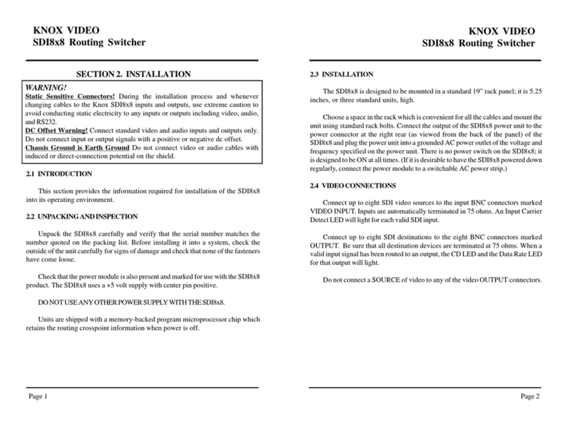
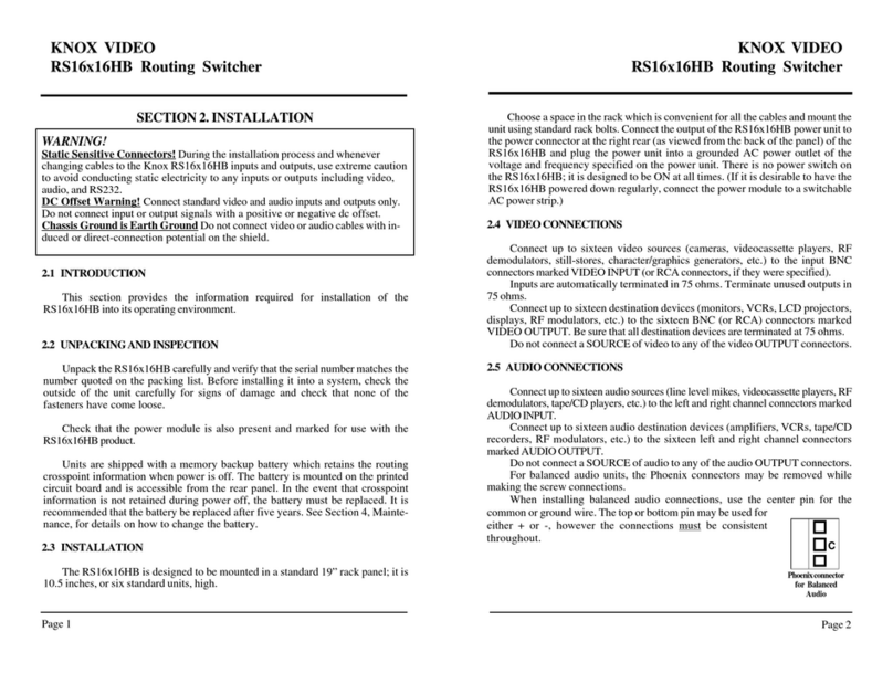
SECTION2.INSTALLATION
WARNING!
Static Sensitive Connectors! During the installation process and whenever changing
cables to the Knox RS8x8HB inputs and outputs, use extreme caution to avoid conducting
static electricity to any inputs or outputs including video, audio, and RS232.
DC Offset Warning! Connect standard video and audio inputs and outputs only. Do not
connect input or output signals with a positive or negative dc offset.
Chassis Ground is Earth Ground. Do not connect video or audio cables with induced or
direct-connection potential on the shield.
2.1 INTRODUCTION
Thissection provides theinformation required for installation ofthe RS8x8HB
into its operating environment.
2.2 UNPACKINGANDINSPECTION
Unpack the RS8x8HB carefully and verify that the serial number matches the
number quoted on the packing list. Before installing it into a system, check the
outsideof the unitcarefully for signs of damageand check that none ofthe fasteners
have come loose. Check that the power module is also present and marked for use
withthe RS8x8HB product.Units are shipped with amemory backup battery which
retainsthe routingcrosspoint information when power is off. Thebattery ismounted
on the main printed circuit board visible through the rear cover. In the event that
crosspointinformation isnot retainedduring poweroff, thebattery mustbe replaced.
It is recommended that the battery be replaced after five years.
2.3 INSTALLATION
TheRS8x8HB is designed to bemounted in a standard 19"rack panel; it is 5.25
inches, or three standard units, high. Choose a space in the rack which is convenient
for all the cables and mount the unit using standard rack bolts. Connect the output
ofthe RS8x8HB powerunit to the power connectorat the right rear (asviewed from
the back of the panel) of the RS8x8HB and plug the power unit into a groundedAC
power outlet of the voltage and frequency specified on the power unit. There is no
powerswitch on theRS8x8HB; it is designed tobe ON atall times. (If it is desirable
to have the RS8x8HB powered down regularly, connect the power module to a
switchableAC power strip.)
2.4 VIDEOCONNECTIONS
Connect up to eight video sources (cameras, videocassette players, RF
demodulators, still-stores, character/graphics generators, etc.) to the input BNC
connectors marked VIDEO INPUT (or RCA connectors, if they were specified).
Inputs are automatically terminated in 75 ohms.Terminate unused outputs in
75ohms.
Connect up to eight destination devices (monitors, VCRs, LCD projectors,
displays,RFmodulators, etc.)tothe eightBNC(or RCA)connectorsmarked VIDEO
OUTPUT. Be sure that all destination devices are terminated at 75 ohms.
Do not connect a SOURCE of video to any of the video OUTPUT connectors.
2.5 AUDIOCONNECTIONS
Connect up to eight audio sources (line level mikes, videocassette players, RF
demodulators,tape/CD players,etc.) tothe leftand rightchannel connectors marked
AUDIOINPUT.
Connect up to eight audio destination devices (amplifiers, VCRs, tape/CD
recorders, RF modulators, etc.) to the eight left and right channel connectors
markedAUDIOOUTPUT.
Do not connect a SOURCE of audio to any of the audio OUTPUT connectors.
For balanced audio units, the Phoenix connectors may be removed while
making the screw connections.
Wheninstalling balancedaudio connections,use thecenter pinfor thecommon
or ground wire. The top or bottom pin may be used for either + or-, however the
connections must be consistent throughout.
2.6 SETTINGTHEBAUDRATE
If the RS8x8HB is to be controlled through its RS232 port, it is important to
set the correct baud rate. One of four baud rates may be selected using position
1 and 2 of the programming switch located on the rear panel of the RS8x8HB. Set
the switches as follows:
C
Phoenixconnector
for Balanced
Audio

KNOX VIDEO
RS8x8HB ROUTING SWITCHER KNOX VIDEO
RS8x8HB ROUTING SWITCHER
Page 5 Page 6
BAUD RATE SWITCH 1 SWITCH2
19200 ON ON
1200 OFF ON
2400 ON OFF
9600 OFF OFF
Switches are ON when pushed to the right (as viewed from the back of the
panel).All Baud Rates are 8 Bit, No Parity, One Stop Bit.
The switches are read by the microprocessor only at power-up; for switch
configuration changes to take effect, cycle the power input to the RS8x8HB.
In the non-verbose mode, only the word DONE will be reported. In either
mode, an incorrect or meaningless command will cause the word ERROR to be
reported.
2.7 ANSWERBACKMODES
The user may choose between two modes of answerback: verbose and non-
verbose. Select the mode using position 3 of the programming switch located on
the rear panel of the RS8X8HB.
Position 3 ON is verbose, while position 3 OFF is non-verbose.
The switches are read by the microprocessor only at power-up; for switch
configuration changes to take effect, cycle the power input to the RS8x8HB.
In the verbose mode, each time a routing command is sent, the current routing
map will be reported on the RS232 line.
OUTPUT1 Video3 Audio 1
OUTPUT2 Video2 Audio 2
OUTPUT3 Video1 Audio 3
OUTPUT4 Video6 Audio 6
OUTPUT5 Video7 Audio 7
OUTPUT6 Video8 Audio 8
OUTPUT7 Video5 Audio 1
OUTPUT8 Video4 Audio 1
1
ON
2345678
Figure2.1 BaudRateSetting
Switches 6-8 should always be off.
Figure2.2
Typical
Routing
MapStatus
Report
2.8 DISABLINGTHETIMEDSEQUENCEMODE
To avoid accidentally enabling the timed sequence mode, turn switch 4 ON.
This will disable the timed mode.
2.9 DISABLINGBREAKAWAYAUDIO
To disable breakaway audio feature, turn switch 5 ON.
2.10 VERTICALINTERVALSWITCHING
Allunits are nowfitted with the vertical switchingoption. Switching will occur
during the vertical interval, referencing the sync signal on input number one. If
input number one has no input, switching will be random with respect to sync.
Note: vertical interval switching has no meaning unless the inputs are synchronous
to one another.

KNOX VIDEO
RS8x8HB ROUTING SWITCHER KNOX VIDEO
RS8x8HB ROUTING SWITCHER
Page 7 Page 8
3.1 INTRODUCTION
This section explains in detail the operation of the RS8x8HB using either the
front panel push-button switches or the RS232 port.
3.2 CONNECTIONS
Connect audio and video sources as described in sections 2.4 and 2.5.There is
no requirement that all inputs be used.
If outputs are left over they may be used like a distribution amplifier to buffer
and distribute an input signal.To use extra outputs in this way simply route the
input you wish to distribute to as many available outputs as desired.
Outputs may be looped back to unused inputs via short cables for the purpose
of adding delays, but be aware that if an output is then routed to that same input,
an illegal condition will exist and the output will oscillate at frequencies which
could spill over onto other crosspoints.
3.3 ROUTINGVIATHEFRONTPANELSWITCHES
3.3.1 HOWTOROUTEAUDIOANDVIDEOTOGETHER
Select the destination (output) you wish to route a signal to and push (and
release) the front panel button with the number; the row of LEDs to the right of the
button you pushed will flash. Then select the source (input) audio and video you
wish to have routed to that output and push the front panel button with that input
number. The row of LEDs will stop flashing and the lamp corresponding to that
crosspoint will then glow steadily.
If you do not push an input button within ten seconds, the LEDs will stop
flashing and the crosspoint will remain where it was.
3.3.2 HOWTOROUTEAUDIOSEPARATELY
Select the destination (output) you wish to route an audio signal only to and
push the front panel button with that number twice (two quick pushes).The row of
LEDs to the right of the button you pushed will flash, as when you route both
signals together. Then select the source (input) audio you wish to have routed to
that output and push the front panel button with that input number. The row of
LEDs will stop flashing and the lamp corresponding to the audio crosspoint will
flash slowly, whilethe LED correspondingto thevideo crosspointwill glow steadily.
If you do not push an input button within ten seconds, the LEDs will stop
flashing and the crosspoint will remain where it was.
SECTION3. OPERATION 3.3.3 HOWTOSTOREANDRECALLCROSSPOINTPATTERNS
TheRS8x8HB has 8stored routingmap configuration memorylocations. These
stored configurations are nonvolatile and are thus maintained during power
interruptions.
To STORE the currently loaded crosspoint pattern to one of the eight pattern
storage areas, push and hold input button #8; an S will appear on the LED display.
Then release button #8 and push an output button, 1 to 8, corresponding to the
storage area you wish to store the crosspoint pattern in.
To RECALL and load one of the stored eight crosspoint patterns from the
front panel, push and hold input button #1; an R will appear on the LED display.
Then release button #1 and push an output button, 1 to 8, corresponding to the
crosspoint pattern you wish to recall.
3.3.4 HOWTOSTARTTHETIMEDSEQUENCER
TheRS8x8HB canbe setto cyclecontinuously throughits eightstored patterns
on a timed basis. To start the cycling, push and hold input button #4.
Push and hold input button #4 again to stop the cycling. The Timed Sequencer
can be disabled by putting switch 4 in the ON position.
3.4 ROUTINGVIATHERS232INPUT
A simple protocol allows all crosspoints to be set through the RS232 port. The
RS232 port will accept inputs from a terminal, computer, or other software-driven
controldevice. Nohandshakingis required.The RS8x8HBRS232port isconfigured
asa DCE. The pinout ofthis port allows connection toa PC-compatible 9-pin serial
COM port with a 1:1 data cable. (Data is sent from the router on pin 2, received on
pin3. Pin 5 is common.)
Note: in the following commands the letters may be upper or lower case;
(ENTER) is the same as Carriage Return (in hex, a 0D). Do not add a Line Feed (in
hex,0A).

KNOX VIDEO
RS8x8HB ROUTING SWITCHER KNOX VIDEO
RS8x8HB ROUTING SWITCHER
Page 9 Page 10
3.4.1 ROUTINGAUDIOANDVIDEO
To route video and audio send a four-byte command in the form:
Bxy(ENTER)
where x is an output number (1-8) and y is an input number (1-8).
To route video alone send a four-byte command in the form:
Vxy(ENTER)
where x is an output number and y is an input number.
To route audio alone send a four-byte command in the form:
Axy(ENTER)
where x is an output number and y is an input number.
To route both video and audio from different inputs, send a six-byte command
inthe form: Bxyz(ENTER)
where x is an output number and y is a video input number and z is an audio input
number.
For example, B123 sends video from input 2 to output 1 and audio from input 3
to output 1.
A crosspoint can be turned OFF by routing it to input zero; e.g. B10 turns off
the video and audio to output 1.
3.4.2 SENDINGASALVOCOMMANDDESCRIPTION
It is possible to send the same input to a number of sequential outputs by a
single eight-byte command of the form:
Xmno(ENTER)
where m is the first output number, n is the last output number, and o is the input
number.
Using X as the first byte sends both video and audio to the range of outputs,
using Y sends video only, and using Z sends audio only.
For example, Y148 sends the audio from input 8 to outputs 1 through 4.
3.4.3 SENDINGASTRINGOFCOMMANDSTOBEEXECUTED
ATTHE SAMETIME
It is possible to send a set of commands to the routing switcher that will be
held until the final command is received, then all the commands are executed at the
same time. For all but the final command in the set use the form:
Exy(ENTER),
where x is the output number and y is the input number.
Using E as the first byte sends both video and audio from input y to output x,
using F sends video only, and using G sends audio only. The final command in the
set must start with the letter B, V, or A instead of E, F, or G. This final command
causes all the previous commands to TAKE. You may also cause a TAKE by
sendingthe three-byte command EE(ENTER).
For example, the following commands sent over a period of time:
E11(ENTER),E22(ENTER),E33(ENTER),B44(ENTER)
will result in connecting input 1 to output 1, 2 to 2, 3 to 3, and 4 to 4 when the last
(ENTER)is received.
3.4.4 USINGCONFERENCEMODE
It is possible to have the video and audio sources from two destinations
cross-connected, as might be used in teleconferencing, by issuing a single
command to the RS8x8. To cross-connect both audio and video from a pair of
inputs and outputs send a command in the form:
Jxy(ENTER),
wherex and yare the two inputs andoutputs. Video and audio from xwill be routed
to y, and video and audio from y will be connected to x.
To cross-connect video only send a command in the form:
Kxy(ENTER),
where x and y are the two inputs and outputs. Video from x will be routed to y, and
video from y will be connected to x.
To cross-connect audio only send a command in the form:
Lxy(ENTER),
where x and y are the two inputs and outputs.Audio from x will be routed to y, and
audio from y will be connected to x.

KNOX VIDEO
RS8x8HB ROUTING SWITCHER KNOX VIDEO
RS8x8HB ROUTING SWITCHER
Page 12
Page 11
3.4.5 STORINGANDRECALLINGCROSSPOINTPATTERNS
To STORE the currently loaded crosspoint pattern to one of the eight pattern
storage areas, send the three-byte command:
Sn(ENTER),
where n is a number from 1 to 8. The pattern stored in that memory area will be
overwritten with the current pattern.
To RECALL and load one of the eight crosspoint patterns in the battery back
up memory, send the three-byte command:
Rn(ENTER),
where n is a number from 1 to 8.
3.4.6 TIMEDSEQUENCER
TheRS8x8HB can be set tocycle continuously through its eightstored patterns
on a timed basis. To set the time interval and start the cycling send the four-byte
command:
Tnnn(ENTER),
where nnn is a one- to three-digit number from 1 to 999.
To stop the cycling, send the two-byte command:
N(ENTER).
3.4.7 LAMPTEST
Thelamp test whichoccurs automaticallyon power-up canbe initiatedthrough
the RS232 port by sending the two-byte command:
T(ENTER)
The lamp test does not disturb the existing crosspoint pattern.
3.5 ANSWERBACKMODES
The user may choose between two modes of answerback: verbose and non-
verbose. Select the mode using position 3 of the programming switch located on
the rear panel of the RS8x8HB. Position 3 ON is verbose, while position 3 OFF is
non-verbose.
In the verbose mode, each time a routing command is sent, the current routing
map will be reported on the RS232 line followed by the word DONE.
The switches are read by the microprocessor only at power-up; for switch
configuration changes to take effect, cycle the power input to the RS8x8HB.
3.6 READINGSYSTEMSTATUS
The crosspoint status can be read from the RS232 port at any time by sending
the two-byte command: D(ENTER)
A condensed version of the status can be read by sending:
D0(ENTER)
The status report does not disturb the existing crosspoint pattern.
OUTPUT1 Video3 Audio 1
OUTPUT2 Video2 Audio 2
OUTPUT3 Video1 Audio 3
OUTPUT4 Video6 Audio 6
OUTPUT5 Video7 Audio 7
OUTPUT6 Video8 Audio 8
OUTPUT7 Video5 Audio 1
OUTPUT8 Video4 Audio 1
In the non-verbose mode only the word DONE will be reported.
In either mode, an incorrect or meaningless command will cause the word
ERRORto be reported.
Figure3.1TypicalRouting MapStatusReport

KNOX VIDEO
RS8x8HB ROUTING SWITCHER KNOX VIDEO
RS8x8HB ROUTING SWITCHER
Page 13 Page 14
SECTION4. MAINTENANCE
NOTE:MaintenanceoftheRS8X8HB,exceptforchangingthebattery,should
beperformedbyqualifiedservicepeopleonly.
4.1 INTRODUCTION
The only routine maintenance the RS8x8HB requires is to change the battery
located at the rear of the RS8x8HB unit.
4.2 HOWTOCHANGETHEMEMORYBACKUPBATTERY
The RS8x8HB is shipped with a memory backup battery which retains the
routing crosspoint information when power is off. The battery, approximately 1/2
inch in diameter, is mounted in a holder on the main printed circuit board. In the
event that crosspoint information is not retained during power off, the battery must
be replaced.
To change the battery pry up the retaining bar gently and slip the old battery
out.Replace at least every five years withKnox partnumber 140896, or commercial
typeDL1220.
4.3 SETTINGTHEBAUDRATE
An 8-position switch, accessible through the rear panel, is provided for setting
the baud rate and certain programming functions. Switch positions 1 and 2 are used
to set the baud rate for the RS232 control port. One of four baud rates may be
selected as follows:
BAUDRATE
19200
1200
2400
9600
SWITCH1
ON
OFF
ON
OFF
SWITCH2
ON
ON
OFF
OFF
4.4 SETTINGTHEANSWERBACKMODE
The user may choose between two modes of answerback: verbose and non-
verbose. Select the mode using position 3 of the programming switch located on
the rear panel of the RS8x8HB. Position 3 ON is verbose, while position 3 OFF is
non-verbose.
In the verbose mode, each time a routing command is sent, the current routing
map will be reported on the RS232 line followed by the word DONE.
The switches are read by the microprocessor only at power-up; for switch
configuration changes to take effect, cycle the power input to the RS8x8HB.
OUTPUT1 Video3 Audio 1
OUTPUT2 Video2 Audio 2
OUTPUT3 Video1 Audio 3
OUTPUT4 Video6 Audio 6
OUTPUT5 Video7 Audio 7
OUTPUT6 Video8 Audio 8
OUTPUT7 Video5 Audio 1
OUTPUT8 Video4 Audio 1
1
ON
2345678
Figure4.1 BaudRateSetting
Figure4.2TypicalRoutingMap StatusReport
Switch position 3 chooses between the verbose and non-verbose mode of
operation (see section 2.7). Position 3 ON is verbose, while position 3 OFF is non-
verbose.
Switch position 4 is used to disable the timed sequencer (see section 3.3.4).
Position 4 ON disables the timed sequencer.
Switch position 5 is used to disable the breakaway audio feature (see section
2.9). Position 5 ON disables the breakaway audio feature.
Switchpositions 6through 8are reservedfor programming options not covered
here. Switches 6 through 8 should always be OFF.

KNOX VIDEO
RS8x8HB ROUTING SWITCHER KNOX VIDEO
RS8x8HB ROUTING SWITCHER
Page 15 Page 16
Inthe non-verbose modeonly the wordDONE will be reported. Ineither mode,
an incorrect or meaningless command will cause the word ERROR to be reported.
Switches are ON when pushed to the right (as viewed from the back of the
panel).
4.5 DISABLINGTHETIMEDSEQUENCER
The Timed Sequencer can be activated accidently from the front panel
pushbuttons. To avoid this condition, disable the Timed Sequencer by putting
switch 4 in the ON position.
4.6 DISABLINGBREAKAWAYAUDIO
To disable breakaway audio feature, turn switch 5 ON.
Table of contents
Other Knox Video Switch manuals