STRAIGHT THROUGH CABLE
1RD+
3TD+
6TD-
2RD-
1RD+
RD-
TD-
TD+
3
6
2
DESCRIPTION SPECIFICATIONS POWER CONNECTION SWITCHES (cont.)
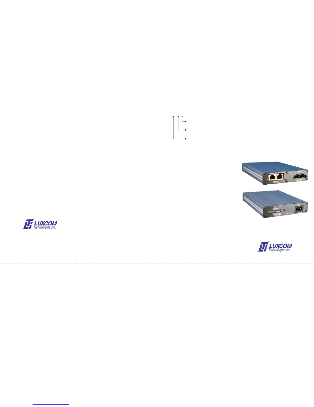
The OM102 media converter has one optical and two Power is derived from an external 100-240V, 50-60Hz cable. This allows connection of devices that do
Optical
electrical ports. It supports 10BASE-T and 100BASE-TX not support auto-negotiation.
Light source ......................... 1300 nm LED MM version
electrical connections. The 100BASE-FX port connects to a FIBER CABLES 100BT/10BT*: Down forces 100BASE-TX mode; up
1300 nm LASER SM version
LAN over a pair of optical fibers. Two OM102s can be forces 10BASE-T mode.
Optical output (62.5/125 fiber) MM version .......... -19 dBm
connected back-to-back to interconnect networks. The OM- The OM-102 media converter is designed to work with 62.5µ
Optical output (9/125) SM version........................ -18 dBm
102 can supply 48 Volts to attached equipment for POE F-Dplx/H-Dplx*: Down forces Full-Duplex mode; up forces
core fibers, terminated with ST connectors at both ends.
Photo detector...................................................... PIN Si
applications. Auto-negotiation provides plug-and-play Half-duplex mode.
-10 Fibers with 100µ core will work, however some optical
Optical sensitivity (10 BER) ................................ -32.5 dBm
operation. Alternately, the copper ports can be manually attenuation may have to be added to insure the receiving
Optical connectors ............................................... SC or ST MDI-X/MDI*: Down forces the electrical transmit and
configured with switches to force duplex, speed, and cross- modem is not overloaded (-14.dBm max). Fibers with 50µ receive pairs to swap (MDI-X); up leaves
over. A serial port allows performance and configuration core will also work, however the smaller core allows about 4
Electrical the transmit and receive pairs normal
monitoring. dBs less light into the fiber. This degrades the allowable link (MDI). The port Link indicator will be on
Data & PoE standards ...................... IEEE 802.3u/802.3af loss from 13.5 dBs to 9.5 dBs. when the 100BT/10BT and the MDI-X/MDI
Power-Over-Ethernet (POE) eliminates power-cube clutter Data I/O connector............................ Rj45 setting are correct.
since the Ethernet cable carries both power and data to each Power source (internal)..................... 100-240V, 50-60Hz MONITOR PORT
device. The OM102 can supply up to 15.4 Watts on each Unit power consumption ................... <3 W 1-Norm / Priority: Down gives Port-1 and Port-2 data equal
electrical port which is the maximum allowed in the 802.3af priority. Up outputs Port-1 data preferential-
An optional cable can be ordered from Luxcom which allows
specification. An IP phone typically uses about 6 Watts . General ly over Port-2 data. This may improve
monitoring of the port configuration, MIB counters, and POE
The OM102 can supply power over either the signal lines or voice quality when an IP telephone is
status. This port reads status only; it cannot change port
the spare lines (but not both). A powered-device (PD) must connected to Port-1. When the modem is
Operating temperature...................... 0°C to +50°C configuration or access data in the ethernet packets. This
be able to accept power from either the signal or the spare ordered with only one port this switch is not
Humidity (RH) ................................... 0% to 95% cable connects to a DB9 serial port on a computer. Typically
lines. The OM102 is normally shipped so that power is available.
MTBF ................................................ > 50,000 hrs HyperTerminal ™ is used; it should be configured to 9600
supplied over the signal pairs. It can be shipped configured Dimensions ....................................... 6.5 * 1.8 * 10 cm baud, 8 data bits, no parity, 1 stop bit, and no flow control.
to supply power over the spare pairs if necessary. Contact * The Auto/Man switch must be up for this switch to have any
the factory if you require this special configuration. effect.
ELECTRICAL SIGNAL I/O LED INDICATORS
APPLICATIONS The RJ45 female I/O connector pin-outs correspond to the INSTALLATION
The OM-102 contains a number of status indicator LEDs, the
IEEE 802.3u standard. A straight through cable or a cross- functions of which are as follows:
10 or 100 Mbps communication systems 1. Connect the Om102 to the mains supply. The POE OK
over cable may be used. If the OM-102 is in Auto-
IP telephones indicator should be on.
negotiation mode no additional setup is required. The figure O-LINK: ON indicates a good optical link; flashing
below shows both cables types. Once the cable is connected indicates data is being input or output.
Wireless LANS
2. Connect the TX fiber of the OM-102 to the RX fiber of
the LINK (Electrical Link) indicator should come on.
Noisy RFI environments - factory floor LINK: ON indicates a good electrical link; flashing the hub, and the RX of the OM-102 to the TX of the hub.
Category 5 cable is recommended; the cable must be less
Secure data environments indicates data is being input or output. The O-LINK indicator should come on.
than 100 meters.
100BT: ON indicates 100BASE-TX mode; off 3. Plug the OM-102 cable into the twisted pair port of the
FEATURES indicates 10BASE-T mode. Ethernet card, preferably using Category 5 twisted pair
POE OK: ON indicates 48 volt power; a single flash
Two electrical ports cable. The LINK indicator should come on. If it doesn't,
indicates a ethernet power fault . Note: that
Supplies power for PoE applications either the cable is faulty, or the remote end does not
the OM102 will drive any 802.3 compatible,
10/100 BaseTX 802.3u compatible support auto-negotiation. In the later case the Om102
powered or unpowered ethernet device.
No external power supply can be forced into a particular mode using the switches.
Single or multi-mode fiber option SWITCHES
Heavily shielded case 4. Once the LINK and O-LINK indicators are on, the
Traffic statistics monitor port modem is fully functional.
The OM-102 has a group switches located on the rear,
Auto or manual configuration these switches are used for the manual settings of the units
parameters. The switch functions are as follows:
Auto/Man: Down enables auto-negotiation and auto
MDI/MDI_X on the electrical ports. This is
the preferred mode. Up enables the P1/P2
switch banks for manual configuration.
1
2
3
6
RD+
RD-
TD+
TD-
TD+
TD-
6
3
RD+
RD-
2
1
CROSS OVER CABLE