manuals.online logo
Brands
  1. Home
  2. •
  3. Brands
  4. •
  5. LUXE BIDET
  6. •
  7. Indoor Furnishing
  8. •
  9. LUXE BIDET Callista User manual

LUXE BIDET Callista User manual

Warranty:
12-Month Limited Warranty to the original buyer from date of purchase that the cabinets will be free from defects
in material and workmanship under normal use.
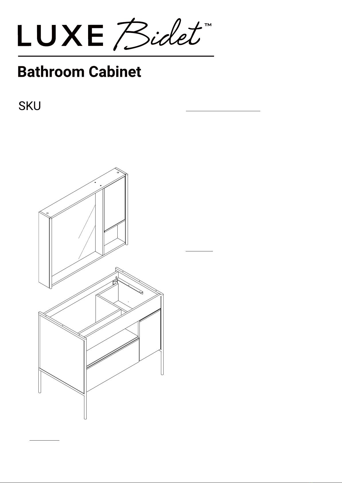
Model : Callista
: CabCallistaGrn Installa�on Manual
Read manual prior to installa�on for important
informa�on about safety, installa�on, use, and
maintenance.
Follow instruc�ons for proper assembly.
Assemble on carpet free of debris to prevent
scratching. Do not subs�tute parts. Do not
over�ghten screws. Do not use if broken or
damaged.
Assembly should be carried out by a qualified
person. Incorrect assembly may lead to furniture
�p-over and may cause injury or damage.
Warning
Serious or fatal injury can occur from
furniture tip-over. To prevent tip-over,
permanently attach product to wall or
floor with included attachment parts.
Fastening components are included,
but consultation with specialized dealer
for advice on suitable screw systems
and fastening devices is recommended.
Safety recommendation:
• Place heaviest items in lowest drawers.
• Do not set heavy objects on top of product.
• Do not allow children to climb or hang on
drawers, doors, or shelves.
• Do not open more than one drawer at a time.
• Use of tip-over restraints may reduce, but not
eliminate, the risk of tip-over.
Use as intended. Inappropriate use may cause
injury or damage.
: CabCallistaMirr
2
M4x16mm. M3.5x13mm.
M4x40mm.
M6x23mm.
#8x35
M6x10mm.
M4x50mm.
M5x50mm.
M4x16mm.
M4x30mm.
A CB D E
F G H J K
L M N O P
Q R S T
U V W X
Y Z AA
(1/4”*2”)
CAM SCREW x42 WOOD DOWEL x52
CAM LOCK NUT x42 SHELF PIN x8 PLASTIC PLUG x6
FLAT HEAD
SCREW x8
FLAT HEAD
SCREW x10
PAN HEAD
SCREW x6
FLAT HEAD
SCREW x30
FLAT HEAD
SCREW x12
PHILLIPS HEAD
SCREW x8
HEX HEAD
SCREW x3 BUMPER CARD x6 HINGE x4 LARGE
BRACKET x4
FLAT HEAD
SCREW x6
FLAT HEAD
SCREW x6 EXTENSION SLIDE x2
EXTENSION RAIL x2
L-WRENCH x1
OUBLE XPANSIOND E
NCHOR xA 8 FLAT WASHER x8
SPRING WASHER x8
HEX BOLT x8
L-BRACKET x2 LOWER BRACE x2
3
Step 1
(12x)
2
M3.5x13mm.
(2 used in this step)
K
S T
AA
Cam Screw
FLAT HEAD SCREW
1
HOW TO USE CAM SCREW
Turn the Cam Screw or
gently tap the until the
shoulder is against the
surface of the part.
Cam Lock Nuts
Push a Cam Lock Nut into
the part. The arrow in the
Cam Lock Nut must point
toward the hole at the
edge of the board.
Insert the Cam Screw into the
Cam Lock Nut. Tighten the Cam Lock Nut.
4
Step 2
Step 3
(2 used in this step)
M3.5x13mm.
K
S T
FLAT HEAD SCREW
3
3
(4x)
AA
Cam Screw
4
5
(2x)
AA
Cam Screw
B
(2x)
Arrow
Cam Lock Nut
(2x)
C
WOOD DOWEL
5
Step 4
Step 5
(4x)
(4x)
(1 used in this step)
3
7
27
M4x50mm.
F
C
AA
B
(4x) Cam Screw
Arrow
FLAT HEAD SCREW
WOOD DOWEL
Cam Lock Nut
(4x)
3
4
5
C
B
(2x)
WOOD DOWEL
Cam Lock Nut
Arrow
Step 6
Step 7
6
(8x)
9
7
C
B
(5x)
Arrow
WOOD DOWEL
Cam Lock Nut
(3 used in this step)
M4x50mm.
F
FLAT HEAD SCREW
9
3
1
4
5
7
Step 8
Step 9
(2x)
AA
LOWER BRACE
(10x)
C
WOOD DOWEL
B
(9x)
Arrow
Cam Lock Nut
7
9
2
10
8
M4x30mm.
(6 used in this step)
R
FLAT HEAD SCREW
M6x10mm.
(8 used in this step)
L
PHILLIPS HEAD SCREW
9
1
Step 10
Step 11
8
M6x23mm.
(3 used in this step)
12
13
M
U
(2 used in this step)
N
HEX HEAD SCREW
BUMPER CARD
L-WRENCH
M4x40mm.
(10 used in this step)
13 14
16
15
15
28
(6 used in this step)
M3.5x13mm.
K
G
S
FLAT HEAD SCREW
FLAT HEAD SCREW
Step 12
Step 13
9
(2x)
M4x16mm.
(4 used in this step)
11
J
O
FLAT HEAD SCREW
HINGE
(8 used in this step)
(1/4”*2”)
V
Y
W
X
1/4”x2”
(6 used in this step)
M4x16mm.
J
Z
Z
(2 used in this step)
FLAT HEAD SCREW
L-BRACKET-2
2
1
Z
(2 used in this step)
L-BRACKET-2
2
10
Step 14
Step 15
(2x)
(2x)
26
21
C
AA
B
(2x)
Cam Screw
WOOD DOWEL
Cam Lock Nut
Arrow
(8 used in this step)
11
(2 used in this step)
N
M4x16mm.
J
FLAT HEAD SCREW
BUMPER CARD
11
Step 16
Step 17
24
(2x)
(3x)
C
AA
B
(3x)
Cam Screw
WOOD DOWEL Cam Lock Nut
Arrow
(6x)
(6x)
26
22
20
19
AA
C
B
(6x) WOOD DOWEL
Cam Lock Nut
Cam Screw
Arrow
12
Step 18
Step 19
(14x)
(9x)
26
24
17
18
C
AA
B
(9x)
Cam Screw
Arrow
WOOD DOWEL
Cam Lock Nut
(4 used in this step)
20
19
M4x50mm.
F
FLAT HEAD SCREW
13
Step 20
Step 21
(6 used in this step)
M5x50mm.
(2x)
P
E
FLAT HEAD SCREW
Q
LARGE
BRACKET
PLASTIC PLUG
M4x16mm.
(6 used in this step)
(2x)
H
P
PAN HEAD SCREW
LARGE
BRACKET
14
Step 22
M4x16mm.
(8 used in this step)
25
(2 used in this step)
J
N
FLAT HEAD SCREW
BUMPER CARD
Step 23
(2x)
M4x16mm.
(4 used in this step)
25
J
O
FLAT HEAD SCREW
HINGE
15
Step 24
(8 used in this step)
23
D
SHELF PIN
A) Attach drawer assembly to assembled unit:
Fit drawer glides of drawer assembly into
corresponding drawer glides of unit. Push
drawer all the way into the assembled unit. Test
the drawer by opening and closing a couple of
times to ensure it is attached.
Assembly is now complete.
B) To remove drawer assembly from
assembled unit:
Fully extend drawer assembly from unit. Locate
plastic tabs on left and right drawer glides. With
even pressure, simultaneously lift the left tab and
push down the right tab and pull the drawer from
the assembled unit.
left drawer
glide
right drawer
glide
6
left drawer
glide
right drawer
glide
16 28/03/22-0 920000324
• Mark the attachment point(s) with a
pencil at the appropriate height.
• Drill 5/16-inch (8mm) diameter hole(s)
through the wall at the height you
marked with pencil.
• Drive the plastic plug(s) into the hole(s),
using a hammer if needed.
Drywall without available wood stud:
• Mark the attachment point(s) with a
pencil at the appropriate height and
positioned over wood stud(s).
• Drill 1/8-inch (3mm) diameter pilot
hole(s) into the wood stud(s), at the
height you marked with pencil.
Masonry:
• Mark the attachment point(s) with a
pencil at the appropriate height.
• Drill 5/16-inch (8mm) diameter hole(s)
2 and 3/4-inches (70mm) deep into
the wall at the height you marked with
pencil.
• Drive the plastic plug(s) into the hole(s),
using a hammer if needed.
Drywall or plaster with available
wood stud:
WALL ANCHORING GUIDE:
The hardware you should use to secure your
furniture to the wall depends on both the
type of furniture you have and your wall
material.
Type of Wall Material:
Using the guide below, identify your wall
material and the appropriate steps to take
for that wall material.

This manual suits for next models

2

Other LUXE BIDET Indoor Furnishing manuals

LUXE BIDET Glantis User manual

LUXE BIDET

LUXE BIDET Glantis User manual

LUXE BIDET Sophea User manual

LUXE BIDET

LUXE BIDET Sophea User manual

Popular Indoor Furnishing manuals by other brands

Regency LWMS3015 Assembly instructions

Regency

Regency LWMS3015 Assembly instructions

Furniture of America CM7751C Assembly instructions

Furniture of America

Furniture of America CM7751C Assembly instructions

Safavieh Furniture Estella CNS5731 manual

Safavieh Furniture

Safavieh Furniture Estella CNS5731 manual

PLACES OF STYLE Ovalfuss Assembly instruction

PLACES OF STYLE

PLACES OF STYLE Ovalfuss Assembly instruction

Trasman 1138 Bo1 Assembly manual

Trasman

Trasman 1138 Bo1 Assembly manual

Costway JV10856 manual

Costway

Costway JV10856 manual

moss DESIGN Caisson Credenza Assembly instructions

moss DESIGN

moss DESIGN Caisson Credenza Assembly instructions

Aquaglide FULL DECK 15.0 owner's manual

Aquaglide

Aquaglide FULL DECK 15.0 owner's manual

AREBOS AR-HE-SW30 user manual

AREBOS

AREBOS AR-HE-SW30 user manual

Till-Hilft Fulda 87005.330 Assembly instructions

Till-Hilft

Till-Hilft Fulda 87005.330 Assembly instructions

Twoey Outside 2010 quick start guide

Twoey Outside

Twoey Outside 2010 quick start guide

Hettich Easys 200 operating instructions

Hettich

Hettich Easys 200 operating instructions

The bedboss RELAX 404 Series owner's manual

The bedboss

The bedboss RELAX 404 Series owner's manual

Oeseder Möbelindustrie Bern 991 720 Assembly instructions

Oeseder Möbelindustrie

Oeseder Möbelindustrie Bern 991 720 Assembly instructions

Costway HW68469 user manual

Costway

Costway HW68469 user manual

Next ALIX A27743 Assembly instructions

Next

Next ALIX A27743 Assembly instructions

BROSA Hans Assembly guide

BROSA

BROSA Hans Assembly guide

Prodigg MINIKA PBA015T-FUR installation manual

Prodigg

Prodigg MINIKA PBA015T-FUR installation manual

manuals.online logo
manuals.online logoBrands
  • About & Mission
  • Contact us
  • Privacy Policy
  • Terms and Conditions

Copyright 2025 Manuals.Online. All Rights Reserved.