Contents
Fer
SCOS
BB
CEN
C0)
Seen
ennn
Ree
EESS
CESSES
EES SSS
SOS
SSSSS
SOOO
ESSE
SESESS
SS
SOEES
SES
ESSSESSSESESSSSEESEESOOEEE
y)
Parts
Locations
and
Dissembly
Instructions
-----
re
rrr
ttre
tte
ee
ct
ences
3
to
4
Adjustment
Procedures
saeupokeadeease
see
soeasbtee
cate
ta
ities
ents
desees
ccshies
shoes
poieme
ewe
densmeltds
ob
hee
Seinseled
oe
ahae
|
niacea
nenteea.
ard
aalbinepwa
ha
cisiis
eocie
selves
gece
erin
se
dev
Seaudteneyy
5
Adjustment
Locations
<--ccccccccceceesteereccetteertceresteeetceneeeceeeesneeecsnecseneeeaseenceneeeeetesecsnnseteeastnaseannieeniacttsasesscesecenecensansneesnees
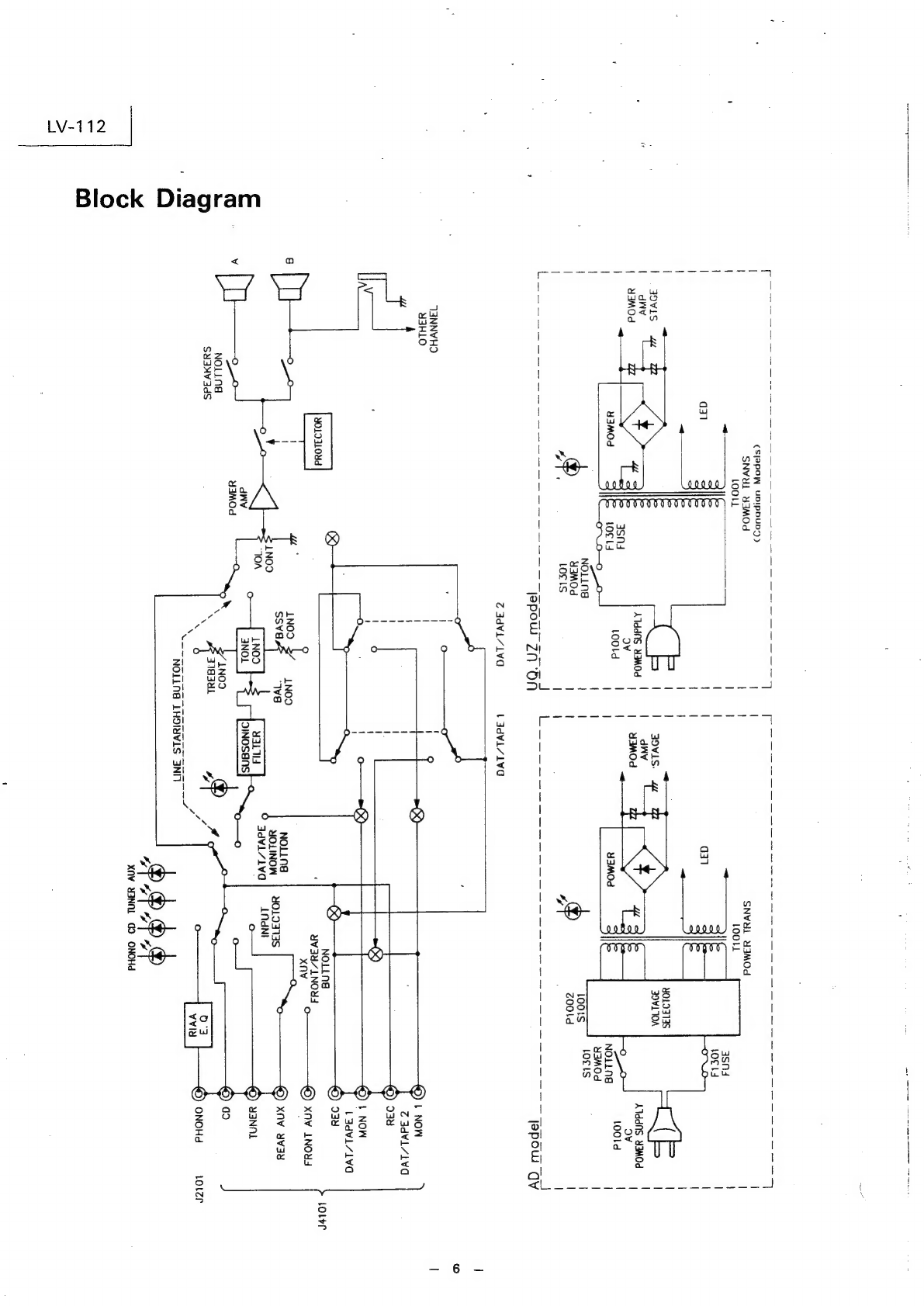
5
Block
Diagram
disnceee
ve
dover
i
Uoweccaeal
eo
Tsede
©
We
sete
aie
os Oe
ES
OSERES
MEET
COM
D
ECO
reas
puNbeD
NNSA
baa
Aleeuion
ce
Wabidl
pen
etuatie
Ped
on
Seeios
aude
Sauls
jashisesumssaineade
cine
iaiees
hak
candace
geusoamaee
6
Schenatic
Diagram
SeRabUate
Pease
eben
bic
FeweVecbysecens
dedeedescudsengeeweescSes
eleiteelte
ed
snnaie’
we
San
Ges
sedes
boa
es
weeSee
see
ecels
see
anos
aemea
ese
rele
wMeu
Se
aesinae
Valcsleaeeewa
wes
7
to
10
Parts
Layout
on
P.C.
Board
&
Wiring
Diagram
Sele
ssice
copesycs
sunbesoe
Ges
chereneer
este
ley
se
Tedeansaing
spose
aawecas
eee
nosing)
oeaeagviegays
ras
eteaece
sa
ll
to
14
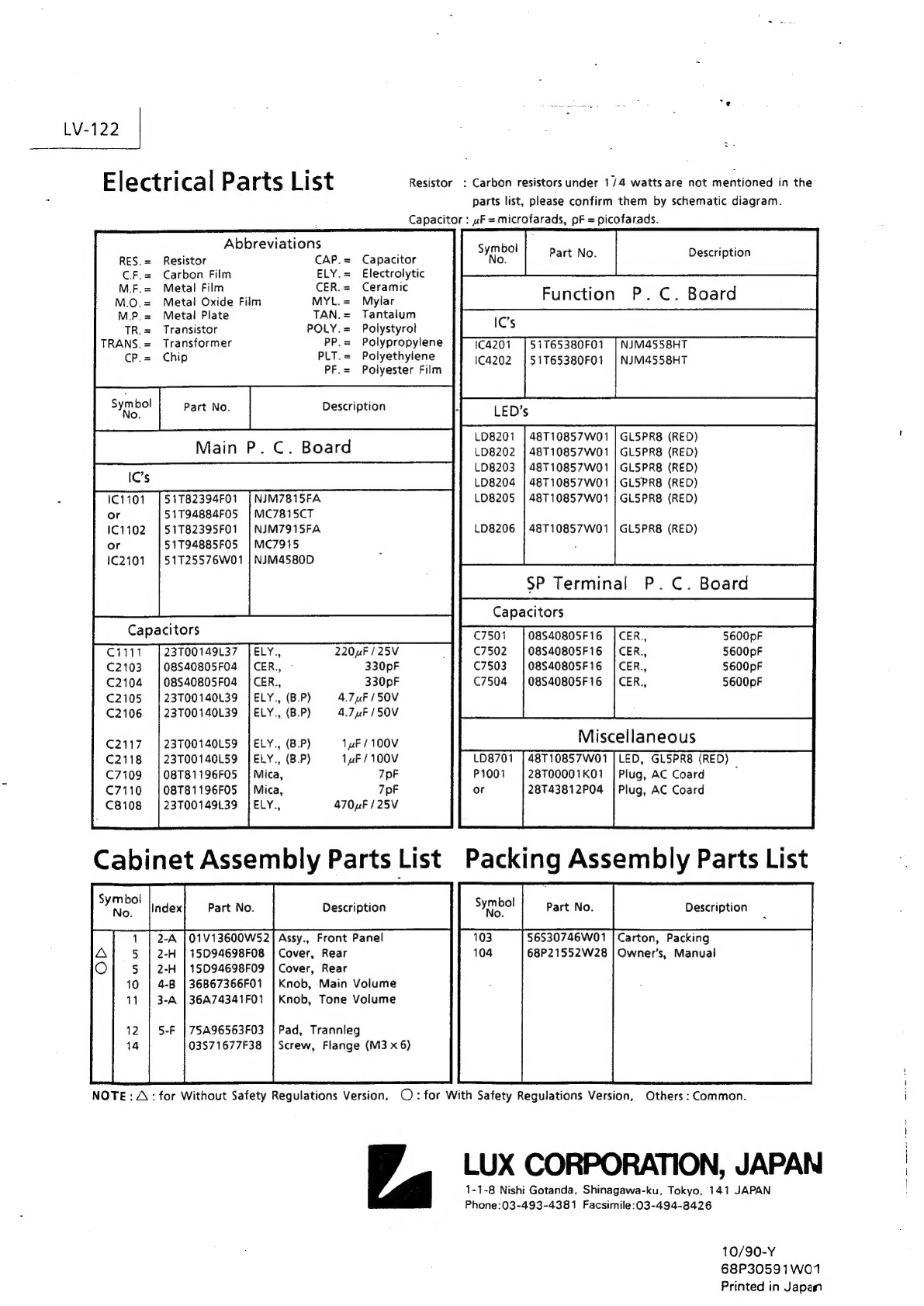
Electrical
Parts
List
‘Juig
Bil
cterocid
wie wis
Gab
e's
pas
oto
aban
wie
eBaseewcns
ae
dade
cweccir
cs
Wececegean
eave
Seles
sey
sely
Medes
Heese
bee
habe
se
eehse
Sais
Seema
eae
oHidee
po
eceeaaed
Sasa
hte
eeeae
15
to
18
Packing
Method
View
entsdcts
ow
vockecns
be
Teta
Rochen
ota
Bees
ian
e
ace
te
SIN
eA
sta
its
eos
ea
tn
ht
acetate
fe
aheth
occa
Alec
dea
tte
19
Packing
Assembly
Parts
List
wiatbiageelesd
vobeaeocteasind
ned
tolcee
fais
eatec
cee
seer
Gasp
eemaes
seve sees
ediacdis
apbasilee
ncactingaubinh
Pease
soe
deaths
dare
y
eae
diane
neeuicdendaaeaehgieigeeh
19
Cabinet
Assembly
Parts
List
Pe
Seb
leaks
cele
seen
daa
Coates
vesdewas
isu
cae
Sate
ce
doers
waar
Jacisiaead
ols
cles
nui
ae
o@atmionincs
cigs
duaaenegsneag.eedtesadale'ee
as ne
Selethouga
sles
de
Va
Te
sldcasdaueale
20
Exploded
View
(Cabinet)
SpPUIEEESEEEEEEECOOSEEEESEOOOSSESOOOOSSESE
COO
SSOSCCOOOSeSEOSSOOEEESS
SOO
OOOOOOOEOOOOOOOOOOOOOOOOCOOOOOOOS
SECO
OEOECO
SCO
OOOOOEESSECEOOESSEOOS
val
to
99
Semi-Conductor
Lead
Indentifications
via
be
din
Seley
cedib.
od
hawle
diclonn
slo
Gis
lepine
o
Xiatm
srettre
x
isla'e)acc's
win's
siejeid
sia
Gesieishals
ists
pis
siels
wines
ore’sivks
wivle
si
dieie.sictatwielaaulé
ata
iatejeie
aatdecratiemayel
23
to
25
Specifications
VLV112AD/UQ/UZ
Power—Out
put
cidive
voiesiebebr'cwce
vee
esse
geingerbing
pee seh
cucce
Sac
suicn
ves
easulaauasin'alatp
cuetaseisns
eruvisn
sae
sedewececves
ens
hee
lecdiaals
nteseeee
55
(0
:
1%
THD
20Hz
~
20kHz)
Headphones
Output
pics
tbaelannnSe
sea
inws
en
ce
ilacads
doses
ve
ededesiswedos
ts
novapeenessisesese
es
acd
decchascesanetec
docs
scatetee
semese
es
55W
(800hms
~
1
kHz)
700nV
+
10%
Input
Sensitivity
(kHz)
Fl
seeds
caa
mie
nensscootpevasseetslasineaTesilesinnciishsasevien
te
SonsRegersansescstascsshateas
CD.
Tuner,
DAT/Tape-1:150nV
+
15%:
DAT/Tape-2,
AUX(L-ch,
Mono):
1500V+15%
Phono(MM)
:
2.
5mV
+
20%
Input
Impedance
(1kHz)
ve
Ta
Raid
ics
ha
ce
Ra
CD.
Tuner,
DAT/Tape-1:40kohm
+
15%
DAT/Tape-2,
AUX:
40kohm
+
15%
Phono
(MM)
:47kohm
=
15%
s
FREQUENCY
RESPOMSE
to
ee
eosin
etek
a
otertiperceteeneettencterct
erst
DAT/Tape-1,
DAT/Tape~2:
(10Hz~100kHz)+1.
-4dB
CD.
Tuner,
AUX:
(10Hz~100kHz)+0.6.
-3dB
Phono
(MM)
:
(100Hz)
13.09
+
1dB
Phono(MM)
:
(10kHz)-13.74
+
1dB
Loudness
Control
(VR-30dB)
cette
he
cedeTSabe
St
Ritual
eveuedas
oacepubvelessneeonevevenuice<actucotieravensces
aut
ee
ah
OE
ah
nel
(100Hz)6
+
2dB
‘
(10kHz)4
+
2dB
Tone
Controls
ccc
es
ereesee
steer
eeeeceeetnsenneceneenneennecatsaecsascanseanieenscuncensacantsaeransnicenssnasansseeeaneenttans
Bass:
(100Hz)
+10+3dB
Treble:
(10kHz)
+
10+
3dB
S/N
Ratio
ree
Leveeseseseueneeeeneesestencersrssesesecassnenansenssisnessscccerescestens
acta
epee
tiaeinienne
aa
CD,
Tuner,
AUX:82.9dB
(Input
Terminal
Shorted)
do
cdasteu
stents
eaccstes
ds
eioecGeutevestae
seid
scdsciess
es
Lecdeaessevestaneracetledesanteagaieriass
DAT/Tape-1,
DAT/Tape-2:78.5dB
Phono(MM)
:64.
9dB
Crass
Talk
(L0kHz)
Vou
dhicnedioestadescaccteils
caladees
ms
bate
dete
Na
ee
Blanca
alae
ees
CD.
Tuner,
DAT/Tape-L
:
40dB
Phono
(MM)
:
30dB
Residual
NOiSe
<cccccccecceeeeeec
ec
ecsceeetceteteeesarceneseeneeneencenssnceeeseiseereeseesencessascusanancescaacecagssacescascassicasenaceenseeenaciecaseasaeens
1.
2nV
Power
Supply
ee
eee
aes
ac
aa
sepa
cts
oe
Daraesa
vats
seleeiawewaceeseerspa
Passteede
ovedteus
ste
steuesisesdaestssawe¥e
ie
caavicce
Metustattns
l
20/220/240V,
50Hz
SOM
LCONC
ue
LOTS
etic
eee
is
etiereneeecinrme
eRe
ee
10IC’s,
19Transistors,
37Diodes.,
42ener
Diodes
Dimensions
dada
deesvoeddsdaredsapivensecscecsseandesesaaseedesgeatsCeecdsavinsendvsstinsesats
Esaxestedsee
dus
sadeevewses¥entaosscsneees
teense
438
(W)
x
137
(H)
x
365
(D)
om
Weight
bina
bnesuiee
vewev'cse'seee
Sali
ses
cvssl'ede
veineadadias
ccaielose
os
sob
sse dee
wealess
Venus
Uncitneles's
ies
sbces
eins
inacs
haces
vosdlg
obs
Sue
ee
Las
bng
se
Suvboraye
nce
ceee
secede
edness
cdbinndeddagdesseneenia
ee
9kg
Note:Due
to
continuing
product
improvement.
specifications
and
design
are
subject
to
change
without
notice.
yy
ee