Luxor/H.Wilson WPS5C User manual

WPS5C | WPS5BC
Assembly Instructions
PLEASE READ ALL INSTRUCTIONS
BEFORE BEGINNING ASSEMBLY
TOOLS REQUIRED:
*YOU WILL NEED A DRILL, 1/4˝ DRILL BIT, CRESENT
WRENCH AND PHILLIPS SCREWDRIVER TO ASSEMBLE
THIS PRESENTATION STATION.
ASSEMBLY TIPS:
* Two people should assemble this product
* Just turn the camlocks until the screw is secure - DO NOT
OVERTURN! Make sure the side of the camlock that you
can put a screwdriver in is facing outward.
* DO NOT attach the door hinge plates when putting the
other hardware on the side panels, you will just have to take
it off later when attaching the doors. The photo showing
hardware placement is only to show you where it attaches.
INSTRUCTIONS:
1. Remove protective film from shelves.
2. THE EXTENSION RAILS ARE DISASSEMBLED BY THE
FACTORY FOR INSTALLATION. Will be put back together in
step 8.
HARDWARE PARTS LIST:
(18) Shoulder Screws & Cam Lock Set
(6) Casters and hardware (in polybag together)
(4) #8 x 1¾˝ Self Tapping Screws
(2) Keyboard Rails (packed together with screws)
(4) Brown Shelf Pins
(2) 17mm Metal Dowel Pin
(34) 4mm x 14mm Tape Screws
(2) Inset Door Hinge & Plate in polybag
(2) Folding Shelf Brackets & screws in polybag
(2) Ratchet Lift Brackets (interchangeable)
(2) Wood Dowel Pins
(1) Door Handle & Hardware (packed together)
(1) Electrical Assembly with instructions (if ordered)
(2) Handles for Adjustable Shelf (packed with screws)
(1) Catch set & three screws
(4) 4mm x 18mm wood screw
(2) Packages of Glue
WOOD PARTS LIST:
SEE CORRESPONDING NUMBER STICKERS
ON PANELS
1
2
3
4
5
6
7
8
9
10
11
12
13
14
15
Right Side
Left Side
Bottom
Back
Fixed Top
Adjustable Top
Right Extension Rail
Left Extension Rail
Adjustable Shelf Brace
Upper Brace
Keyboard Door
Keyboard Tray
Adjustable Shelf
Large Door
Folding Shelf
Thickness
¾˝
¾˝
¾˝
¾˝
¾˝
¾˝
1˝
1˝
¾˝
¾˝
¾˝
¾˝
¾˝
¾˝
¾˝
Width
29˝
29˝
18˝
18˝
11 ¾˝
19˝
4 ³⁄˝
4 ³⁄˝
3 ¹⁄˝
3 ¼˝
5 ¼˝
17 ⁄˝
18˝
17 ⁄˝
12˝
Length
26 ³⁄˝
26 ³⁄˝
25 ⁄˝
21˝
21 ¼˝
21 ¼˝
11 ¹³⁄˝
11 ¹³⁄˝
15 ¾˝
18˝
17 ⁄˝
13 ¾˝
23 ⁄˝
21˝
18˝
Extension Rail Seperated
Updated 11/06/12 Page 1

3. Keyboard rail, 1/2 of extension rail & lift bracket are factory assembled
Install Metal Dowel Pins & Shoulder Screws on BOTH Side Panels as shown above. Shoulder screws - Threaded
end into the holes shown above and tighten until fully seated - do not overturn!
Metal dowel pins - Press into hole shown above.
Brown shelf pins *These may also be placed later if you are unsure of where you would like your interior shelf.
Camlock - insert into predrilled hole making sure that the side with the slot for screwdriver is facing outward and
that the opening is where the camlock screw sill fit when panels are put together.
*Hinge plates are shown above for placement only. Do not attach at this time. Refer to this page throughout
assembly.
****The RIGHT SIDE PANEL IS SHOWN ABOVE (#1) - THE LEFT SIDE (#2) IS THE MIRROR IMAGE WITHOUT THE
HOLES FOR HINGE PLATES.
Page 2

Page 3
Back Panel Bottom Panel
Left Side
4. Lay left side panel (#2) flat on floor. Take back panel (#4)
and place camlocks into pre-drilled holes. Fit holes in back
panel over shoulder screws so the camlocks are inside.
Tighten camlocks. Insert camlocks into bottom shelf (#3).
Place bottom shelf pre-drilled holes over the shoulder screws
in left side so that the front edge is recessed approximately
1/2" from the front of the side panel - camlocks will be on
the underside of the shelf. Tighten camlocks.
5. Place Keyboard
Door (#11) over
Metal dowel pin
on left side panel.
(Photo shows hole
and pin, it will be
upright 90° angle,
flush with edge.
6. Place predrilled hole
in upper brace (#10) over
shoulder screw in left side
panel. (Upper brace has
wood dowels factory
installed. Put included glue
on dowell before putting in
Hole.) Tighten camlock.
7. Line hardware on right
side up with the predrilled
holes in the keyboard door,
upper brace, bottom and
back panels. Fit together
and tighten all camlocks.
Keyboard Door
Metal Dowel Pin
Left Side
(Right Side
Not Shown)
Upper Brace
Right Side
Upper Brace
Keyboard Door
Bottom
Back
Left Side
2 People Should
Assemble This Product!
Keyboard Rail
Camlocks
Camlocks go in
the underside of
the bottom shelf
***Make suree the side of the camlock that you can put a
screwdriver in is facing outward.
Bottom Panel is recessed ½"
not flush with edge of left &
right panels

8. Place 4 shoulder screws in Adjustable Shelf (#13) as shown (a).
Place camlocks in Adjustable shelf brace (#9) and put onto the
shoulder screws that are closer together on the Adjustable Shelf.
Place Extension Rails/adjustable brace over remaining shoulder
screws (b) Secure the brace and rail assembly together using
# 8 screws (c). Tighten camlocks. Attach the ratchet lift brackets
to predrilled holes in adjustable shelf using 4mm screws (d, e & f)
Adjustable shelf
Screws
go here
to attach
adjustable
shelf brace
& extension
rails
9. Slide keyboard rails all the way out. Lay keyboard
tray on tabs. Attach Keyboard Tray to Keyboard rails
from underneath using the screws that came packaged
with the rails.
Keyboard Rails
Underneath view of
Keyboard Tray
Keyboard Door
10. Slide Adjustable Shelf Assembly onto the rails that were
factory assembled earlier (right). Attach the right and left lift
brackets to predrilled hole in side panels. Line shelf handles
over predrilled holes on the top of adjustable shelf. Fasten
from underneath with the screws that were packaged
with the handles.
Page 4
Predrilled holes for
shelf handles
Shoulder Screws
Shoulder Screws
12. ELECTRICAL ASSEMBLY (IF PURCHASED) -
Positioning shown Above See adjustable shelf picture at
the top right of this page. Attach electrical assembly
with the cord management wrap on the side closest to
the main door. See enclosed electrical instructions.
11. Attach the slide locks to the adjustable
shelf assembly using 4 pcs 4mm x18mm
wood screw as shown below. (Shown
without top shelf attached.)
A
Adjustable shelf brace
Attach Electrical assembly
onto these holes
After Step 8. these parts are
referred to as the adjustable
shelf assembly.
B
C
e
D
Ratchet Lift Brackets - Attach to Adjustable
Shelf with 4mm x 14mm screws and to side
panels with 10mm x 14mm brass screws
Extension rail assembly
f
Step 9

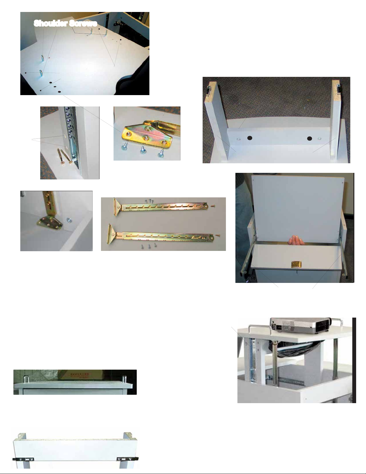
13. Place camlocks in predrilled holes in fixed shelf (#5).
Open glue. Put some glue in the hole for the wood dowel
(see photo left). Place one wood dowel and one shoulder
screw on the top of each side panel (wood dowel will be
closest to the adjustable shelf). Put some glue on the other
end of the wood dowel. Line up the pre drilled holes on the
underside of the fixed shelf to the dowels and shoulder
screws on the top of the sides. Tighten camlocks.
Door Adjustment:
Up-Down Adjustment - Loosen Height adjust-
ment screws. Adjust door and retighten. (A)
Side to Side Adjustment - Turn screw B as
required. (B)
In-Out Adjustment - Loosen screw C and place
hinge arm in desired position. Retighten. (C)
14. Lay unit on its right side. Get door hinges.
Align pre-drilled holes in door with hinges. Tap
one insert, then the other until flush with door.
Attach with screws. Re-attach hinges to right side
panel. Align door handle over predrilled holes on
door (placement shown right). Attach with the
screws that were packaged with the hinges.
15. Attach brackets to folding shelf as
shown right. Attach to side panel lining
holes in brackets up with the predrilled
holes on the side panel.
17. Put casters onto the side panels, lining them up
with the predrilled holes. Secure in place with the
nuts and bolts that came in the caster bag. Make
sure nuts are tightened properly with cresent wrench.
18. Turn unit right side up. Place adjustable inner
shelf at desired height.
16. Place Magnetic Catch into predrilled holes in
the tray & side panel as shown below. Fasten
with included screws. Don’t overtighten.
Underside of folding
shelf
Attach with
1 screw
Magnetic Catch
Attach with 2 screws
*Please make sure you have tightened all camlocks - do not overtighten!
Page 5
Place caster sockets over
predrilled holes on side panels.
This manual suits for next models
1