Luxul PWK6-24-FC2 User manual

WG103 AP Included
FCC
CERTIFIED
Congratulations on your purchase of the Luxul Pro-WAV™ Range Extender
Kit! You are just minutes away from enjoying the benefits of a farther
reaching, clearer wireless signal in your home or office.
LuxuL WIRELEss PRoDuCTs CovERED by ThIs GuIDE
PWK6-24-FC2 - Pro-WAV 1W 2.4GHz outdoor Wi-Fi Range Extender Kit
PRO-WAV™ Wi-Fi OutdOOR
RAnge extendeR/BRidge Kit
QuiCK inStALL guide

QuiCK inStALL guide
PRo-WAv™ InDooR boARD MounTED RAnGE ExTEnDER KIT
MODEL NUMBER: PWK6-24-FC2
© 2010 by Luxul Wireless Inc. All rights reserved
No part of this publication may be modified or adapted in any way, for any purposes
without permission in writing from Luxul Wireless, Inc. (Luxul). The material in this manual is
subject to change without notice. Luxul reserves the right to make changes to any product
to improve reliability, function, or design. No license is granted, either expressly or by impli-
cation or otherwise under any Luxul Wireless, Inc., intellectual property rights. An implied
license only exists for equipment, circuits and subsystems contained in Luxul products.
This product is covered by one or more U.S. and foreign patents.
Patents: 7,783,270, 7,379,717, 6,606,075, 6,373,448, other patents pending
SHOCK-WAV™ WI-FI SIGNAL BOOSTER NETGEAR®
MoDEL nuMbER: PW-FC2 MoDEL nuMbER: WG103
FCC ID: W59PWFC2 FCC ID: PY308400097
IC: 8584A-PWFC2 IC: 4054A-08400097
Luxul Wireless, Inc. NETGEAR, Inc.
357 South 670 West, Suite 160 350 East Plumeria Drive
Lindon, UT 84042 San Jose, California 95134-1911
www.luxulwireless.com www.netgear.com
PRoFEssIonAL InsTALLATIon ConsIDERATIons
The Luxul Wireless Pro-WAV Wi-Fi Range Extender System is required to be professionally
installed. The following components are approved for use in the system.
• Luxul Wireless Shock-WAV PW-FC2 Wi-Fi Signal Booster
• Luxul Wireless X-WAV™ XW-24-FP7 Flat Panel Antenna
• Netgear ProSafe WG103 Access Point
• Netgear Omni antenna included with WG103 access point
The output power of the amplifier is set and tested during manufacturing. There are no user
modifiable parameters in the amplifier. The Luxul Shock-WAV Wi-Fi Signal Booster system
incorporates a Digital AGC (D-AGC) that ensures a consistent and approved output power.

QuiCK inStALL guide
ThE PRo-WAv RAnGE ExTEnDER KIT InCLuDEs ThE FoLLoWInG:
• Shock-WAV™ 802.11b/g Signal Booster
• X-WAV™ CP (Circularly Polarized)
Antenna
• Two Coax Cables
• Ethernet Cable
• POE (Power-Over-Ethernet) Injector
• 48VDC Universal Input Power Supply
• Outdoor Antenna Mounting Bracket
• Quick Install Guide
• Netgear ProSafe Access Point.
– Included with the Netgear is: a
Detachable Antenna, Ethernet Cable,
Power Supply, Installation Guide,
Warranty/Support Information Card
and Resource CD.
ADDITIonAL ITEM REquIRED
External Ethernet cable from your data/network source (Max. length 329’ or 100 meters).
oPTIonAL EquIPMEnT
• Luxul Wireless has a wide variety of cables available and can also make custom cables
for your installations. Contact sales@luxulwireless.com for more information.
• For creating a bridge you may want a second PRO-WAV™ Outdoor Range Extender/
Bridge Kit.
ConFIGuRE youR AP
See the guide included with your AP and configure the AP before you connect the Luxul
Range Extender kit. Once the AP is configured, disconnect all power and connect the
Luxul Range Extender Kit.
CAUTION: Disconnect all power before connecting or disconnecting any cables
or coax to or from this device. Failure to do so will void your warranty.

QuiCK inStALL guide
AssEMbLE ThE RAnGE ExTEnDER KIT
1. Position the X-WAV antenna outdoors so that it points towards the desired
coverage area
2. Feed the WBC™-400 Coax cable (the thicker coax) through the wall to your
buildings interior where the signal booster and AP will be located.
ConnECTInG ThE CoAx CAbLEs
1. Connect the X-WAV antenna to the Shock-
WAV Wi-Fi Signal Booster using the N-Male to
N-Male cable. Be sure to connect the cable to
the side of the Shock-WAV Wi-Fi Signal Booster
labeled “Antenna”.
2. Remove the stock antenna from your AP. Set
aside the stock antenna, you will not need it for
this installation.
3. Using the included N-Male to RP-SMA cable
connect the Shock-WAV Wi-Fi Signal Booster to
the antenna port of your AP. Be sure to connect
the cable to the side of the Shock-WAV Wi-Fi
Signal Booster labeled “INPUT”.
PoWERInG oPTIons
For maximum flexibility you may power the Pro-WAV Outdoor Range Extender/Bridge
Kit by Direct Power or POE using the Luxul Wireless POE Injector or a POE injector that
supports legacy mode. The Luxul Wireless Signal Booster does not support 802.3af POE
power. (Check POE’s documentation).
FIGURE 1
INPUT
ANTENNA
OUTDOOR
INDOOR
POE
OUT
POE
IN
48V
DC IN

QuiCK inStALL guide
POE (Power Over Ethernet) (Figure 2)
1. Connect the Ethernet cable from your data/network
source to the “48V POE IN” port of the Wi-Fi Signal
Booster.
2. Connect the next Ethernet cable from the “POE OUT”
of the Wi-Fi Signal Booster to the “10/100M” port of
your Netgear AP, (See AP’s documentation).
3. Be sure all cables are connected securely and power
up your POE injector.
4. You may now power your POE injector.
POE with the POE-1Port Injector (Figure 3)
Install the POE injector where you have access to your
data/network source Ethernet cable and power sources.
NOTE: The POE-1Port is a non
802.3af/at compliant injector
Direct Power: (Figure 4)
NOTE: If powering the Shock-WAV
Signal Booster directly the
“POE OUT” port is disabled.
1. Connect the Ethernet cable from your data/network
source to the “10/100M” port of your Netgear AP,
(See AP’s documentation).
2. Attach the Luxul power supply (48VDC) to the “48V DC
IN” port of the Signal Booster.
3. Connect Netgear power supply to the AP’s power
port (See AP’s documentation).
4. Plug the power supplies into your power source. FIGURE 4
Data
Source
Power
Source
Data
In
(Ethernet)
Power
In
Data/Pwr
Out
(Ethernet)
POE-
1port
Injector
INPUT
ANTENNA
OUTDOOR
INDOOR
POE
OUT
POE
IN
48V
DC IN
ETHERNET
POWER
Coax 195
Coax 400
INPUT
ANTENNA
OUTDOOR
INDOOR
POE
OUT
POE
IN
48V
DC IN
ETHERNET
POWER
Coax 195
Coax 400
FIGURE 2
FIGURE 3

QuiCK inStALL guide
DEPLoyMEnT
The Pro-WAV PWK6 Outdoor Range Extender/Bridge Kit is designed to be placed on
the exterior of a structure adjacent to the desired coverage area. For best results, the Kit
should be deployed where the maximum amount of signal can be sent throughout the
desired coverage area. The flat panel antenna included in the Wi-Fi Range Extender Kit is a
directional antenna and should be pointed toward the desired coverage area, similar to aim-
ing a flash light. Use the adjustable antenna mount included in the kit to aim your antenna.
Placement Within Your Coverage Area
Luxul Wireless products, particularly those implementing our patented booster products,
are often capable of emitting enough signal strength to cover an entire coverage area re-
gardless of orientation. However, for best results, the deployment suggestions, figure
6, are recommended.
FIGURE 5

QuiCK inStALL guide
PRo-WAv PWK6 As A bRIDGE
Your Access Point allows you to connect many wireless devices to one network connec-
tion. Adding a bridge to your wireless network allows you to extend that one network
connection into an area where you don’t want to, or can’t, run a cabled connection. The
Pro-WAV PWK6 Outdoor Range Extender/Bridge Kit allows even further wireless con-
nections between APs. At Luxul Wireless we recommend using separate APs to create
a wireless bridge, (Figure 6) instead of setting up an AP as a repeater because of the
amount of signal throughput that is lost. Check your APs documentation for instructions
on setting up a wireless bridge.
Even though the Pro-WAV PWK6 Outdoor Range Extender/Bridge Kit is capable of send-
ing signal through most obstacles you will want to be sure that the antennas that make
up your wireless bridge have line of site to each other and are aimed as close as possible
directly at one another.
For more information on deploying a bridge contact [email protected]om.
FIGURE 6
Ethernet
Coax
Router
AP
Wireless Network
Wireless Bridge
Network Source

Results may vary depending on building layout, type of construction and other environmental factors
including Wi-Fi traffic, Microwave Ovens, Cordless Phones etc.
FCC NOTICE: The use of all radio equipment is subject to regulations in each country. To comply with FCC part
15 rules in the United States, radio equipment must only be used in systems that have been FCC certified. It is the
responsibility of the user/professional installer/operator to ensure that only approved equipment/systems are
deployed. To ensure FCC part 15 compliance, Luxul amplifier products should only be installed in certified systems
by licensed professionals.
FCC Certification Support for OEMs: Luxul Wireless offers FCC certification assistance and engineering support
for qualified OEM’s interested in certifying complete amplified WLAN systems. Please contact us for details.
LUXUL WIRELESS | 357 South 670 West, Lindon, UT, 84042
p: 801-822-5450 f: 801-822-5460 | www.luxulwireless.com
LUX-QIG-090320101237-PWK6FC2
© 2010 Luxul Corp. All rights reserved.
TRoubLEshooTInG
Weak or non-existent coverage.
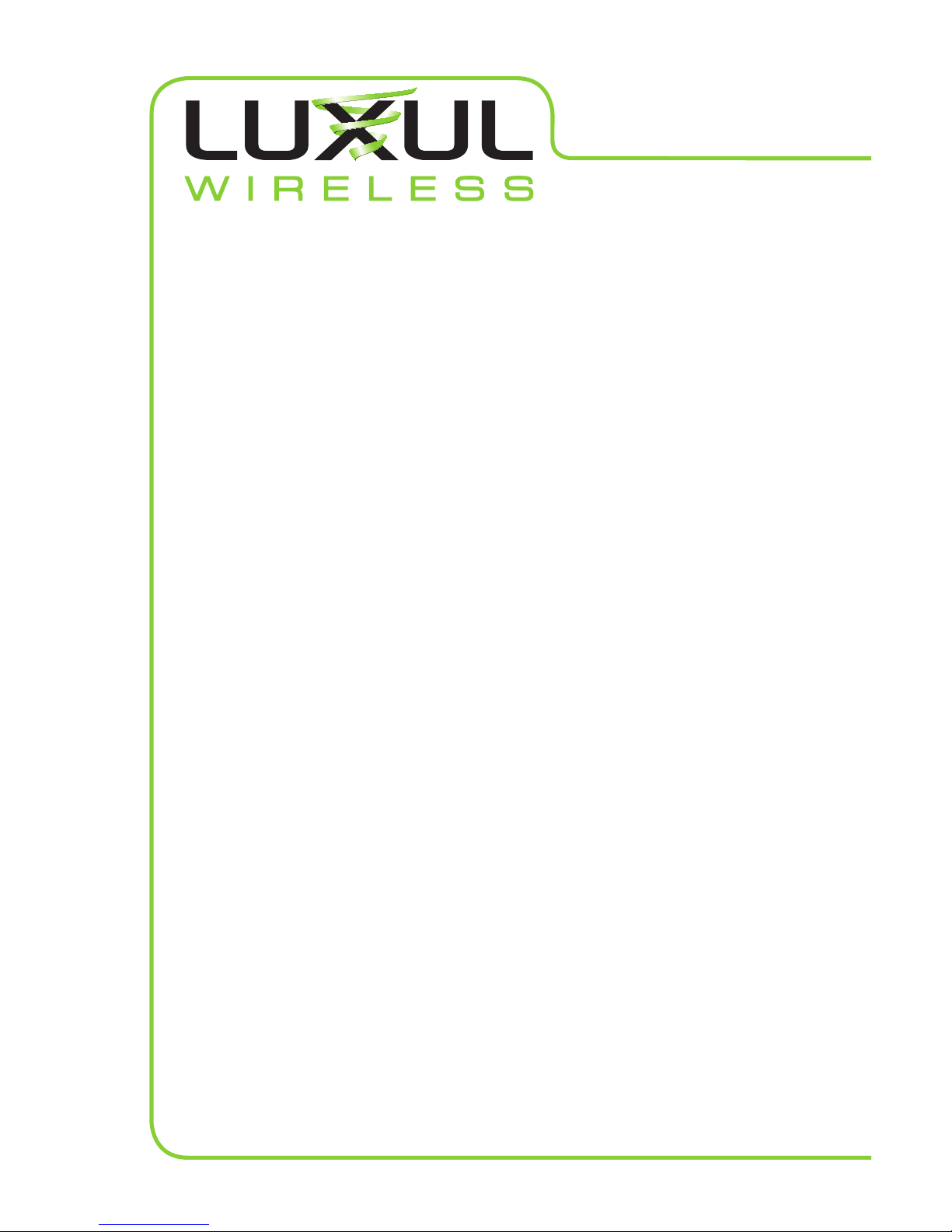
• Make sure the cables are properly connected and that there is power to the Shock-WAV
Wi-Fi Signal Booster and your WAP (Wireless Access Point).
• If the Signal Booster is powered the Power and TX/RX indicators will be solid green. If
data is passing through the signal booster the TX/RX indicator will be Green with flashing
Red. If there is no indication of data pass through remove the Luxul unit and test with
the WAPs stock antennas to make sure the WAP’s radio is transmitting. If the WAP is not
transmitting check your WAP’s documentation for possible causes.
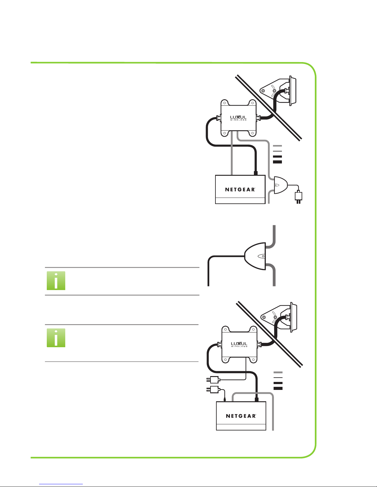
• Sometimes, WAP’s with multiple antennas have primary and secondary antenna ports.
Be sure to connect the signal booster to the primary antenna port of the WAP as many
secondary ports are receive only, or do not transmit at the same power level as the
primary antenna port. If your WAP has more than one antenna port, try connecting
to a different port and/or, if available, change the administration settings disable the
secondary antenna port. (See your WAP’s documentation).
• Ensure the X-WAV antenna is properly positioned. Directional antennas should face the
direction of the area to be covered. Omni antennas should be centered in the desired
coverage area. Antennas should have minimum of 2 feet (.6 meters) of clearance with
no obstructions.
• The Luxul Wireless Circular Polarized signal is superior for penetrating wood, concrete,
and stucco, but all wireless signals can be disrupted by certain obstructions, including
large metal objects, or strong magnetic fields. Try orienting the antenna where line-of-
sight access to the desired coverage area is available.
After checking the above items, if your Luxul Wireless product still does not seem to be
functioning properly, please contact Technical Support at: [email protected]om
For warranty information please go to: www.luxulwireless.com/warranty/
Table of contents
Other Luxul Extender manuals

Luxul
Luxul PW-200-24-Lite User manual

Luxul
Luxul Pro-WAV 200 PW200-24-FC2 User manual

Luxul
Luxul X-WAV XWK1-24-FP14 User manual

Luxul
Luxul P40 User manual

Luxul
Luxul Pro-WAV 100 Lite User manual

Luxul
Luxul SWM-1000-O User manual

Luxul
Luxul SWM-1000-I User manual

Luxul
Luxul PWK1-24-FC2 User manual

Luxul
Luxul PRO-WAV PW-FC2 User manual

Luxul
Luxul PW100-24-FC2 User manual