9
TROUBLE SHOOTING
The AERO2GEN is design to give many years of reliable service as it contains really only two moving parts and one
electronic component; they are the permanent magnet disc magnets, the slipring brush assembly and a rectifier.
The only parts that can wear are: Main bearing ball races, pivot shaft ball races, and the carbon brushes which make
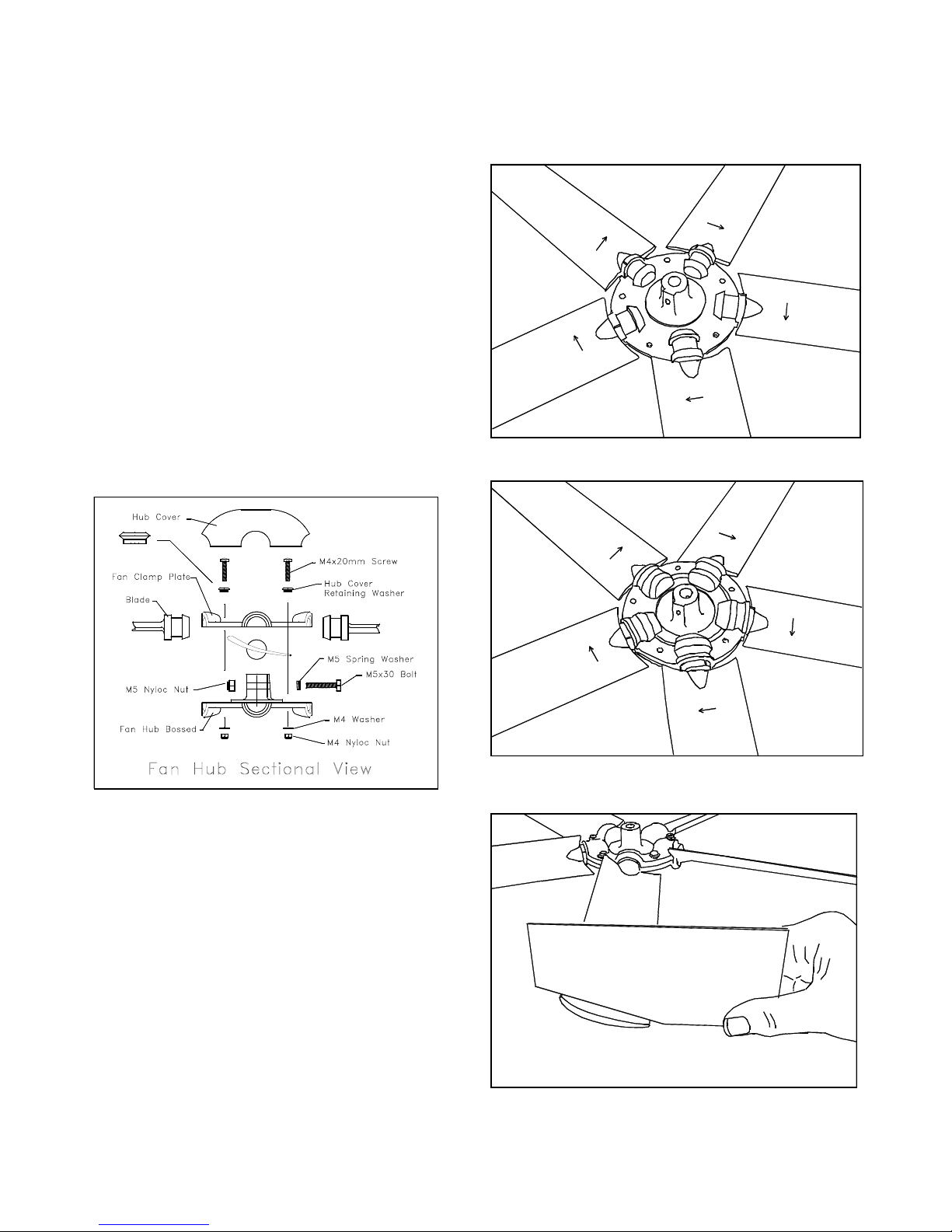
contact with the sliprings. For safety reasons fan blades are designed to brake off if by accident an arm or hand is caught in
the fan.
SIMPLE TEST
A simple test to prove there is an output voltage from the generator can be carried out whilst the generator is in it's working
position. Disconnect the generators output cable from the battery, or the TB regulator if fitted. With the fan turning in the
wind and the two output leads open circuit, allow the fan to build up speed, then touch the two output leads together
(shorting them) the fan should noticeably slow down and act as a brake. If this does not happen, check that your extension
wire connection from the actual generators output cables are not corroded or have become disconnected. If there is a fuse
fitted in the output cable check it has not blown.
The above test can also be carried out by turning the generators main shaft by hand (any direction) to check the braking
action.
Note: Although the instruction sheets supplied with the generator warns you not to run the generator in an open circuit
condition the tests can be carried out safely at wind speeds of up to 20 knots.
(The reasons we do not recommend generators be left in an open circuit condition is that at very high wind speeds the
suppression capacitor maximum voltage may be exceeded and destroyed.
The following tools and equipment will be needed to carry out tests and repairs to the generator.
A multimeter which can read 0 - 100 volts DC, measure resistance, have a diode test, and a continuity (buzzer test).
Pozi drive screwdriver.
Circlip pliers.
Soldering iron and solder.
Hammer.
Piece of hardwood, and a brass rod 12mm diameter X 250mm long or similar.
For pivot bearing replacement, a bench vice will be required.
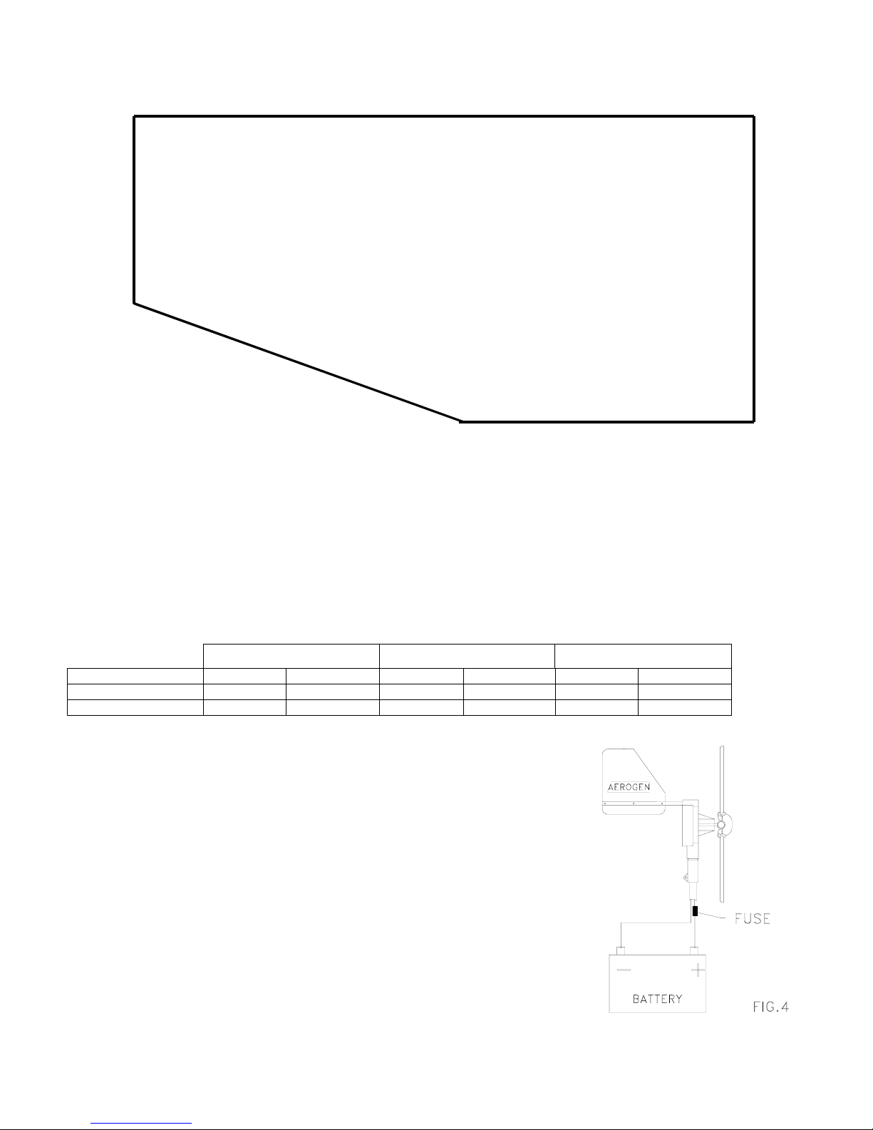
MEASURING OUTPUT VOLTAGE
With the generator in its operating position, disconnect the generators output cable from the battery or the TB regulator if
fitted, and attach a multimeter set on 0 - 100 volts dc range to the two output leads.
The following open circuit voltages should be obtained at the wind speeds shown below. It is most important that the wind
speed is measured at the same height the wind generator is mounted.
12v Model
6 knots = 12v 10 Knots = 25v 15 knots = 42v
24v Model
6 knots = 24v 10 Knots = 50v 15 knots = 84v
If you have a lathe or some other means of turning the main shaft at a known RPM a 12v model produces 0.04v per rev.
and a 24v model 0.08v per rev.
If no voltage is present, check that your extension wire connection from the actual generators output cables are not
corroded or have become disconnected. If there is a fuse fitted in the output cable check it has not blown. Check output
voltage again at the generators actual output cable. If there is still no voltage output, go to the instructions and tests listed
under heading NO OUTPUT.
REDUCED OUTPUT
Check blades are set at the correct angle, and the concave side (hollow side) of the blade faces the wind.
NO OUTPUT
Remove the generator from mounting, taking off the tailfin and fan assembly. Remove the brush cover (4 off screws).
A component called a rectifier that converts the single phase A/C output voltage of the stator into D.C volts is mounted on
right hand side of the slipring housing.
Unsolder the two output wires from stator which are attached to the centre terminals of the rectifier marked ~. No need to
remember which order or terminal they come from, as they can fit on any of the two centre terminals.
Using a multimeter set on resistance measurement (ohms) check the resistance of the two output wires from the stator.
They should read 11.3 ohms 12v model, 44.0 ohms 24v model.