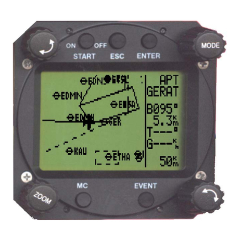
LX Navigation Traffic monitor 57 User manual

Traffic monitor
user’s manual
www.lxnavigation.com

1
Traffic Monitor 57
Traffic Monitor 80
User’s manual
(version 1.8)
Refers to Traffic Monitor FW version 1.8
Made in Slovenia.
Copyright © 2022, LX navigation d.o.o., all rights reserved. www.lxnavigation.com

Document Name:
Traffic Monitor user’s manual
Version: 1.8
Page 2

Document Name:
Traffic Monitor user’s manual
Version: 1.8
Page 3
Contents
PART ONE – OVERVIEW 5
Overview 5
Operation 5
PART TWO – INSTALLATION 8
2.1 Mechanical installation 8
2.2 Electrical installation 8
2.6 Update procedure 9
2.7 Technical specifications 10
PART THREE – INTERFACE 11
Primary pages overview 11
Radar page 11
TP page 12
APT page 14
Flarm warning 16
Info page 16
Flight statistics page / Logbook 16
Setup page 17
Voice 17
Pages 18
Graphic 18
Transfer 20
Units 22
Warnings 22
NMEA 24
Localization 24
Service 24
Shutdown 25
PART FOUR – CONNECTIVITY 26
4.1 SD card 26
PART FIVE – CONFORMITY 27
5.1 Declaration of CE Conformity 27
5.2 Environmental data 28
TIPS, TRICKS & TROUBLESHOOTING 29

Document Name:
Traffic Monitor user’s manual
Version: 1.8
Page 4

Document Name:
Traffic Monitor user’s manual
Version: 1.8
Page 5
PART ONE – OVERVIEW
1.1 Overview
The Traffic Monitor is a FLARM radar and warning displaying unit with a bright, transflective technology
display, which offers the pilot multiple navigation pages. It is a final glide calculator and navigation system
with airspace support, audio warnings and voice messages.
The unit is capable of providing APT (airport), TP (turnpoint), and RTE (Route) navigation on three dedicated
navigational pages. It also has a page showing detailed information regarding nearest objects with additional
options. Navigation pages feature Navboxes, and Airspace, airports and turnpoint information is shown
graphically.
The Traffic Monitor is designed to be installed into a standard 57 mm or 80 mm aviation instrument hole,
depending on which size you have.
As an integral part, it has a 3.5” sunshine readable transflective LCD display (80 mm version) and a 2.5”
screen (57 mm version) to show all user-defined data during flight.
For accessing all system options, two push-rotary knobs and two push buttons are used. A voice module is
also built-in for audio warnings.
It also boasts 16 GB of internal memory, used for storing flights, aircraft info, databases etc.
The unit has the capability to be updated to any later FW version free of charge.
(Visit www.lxnavigation.com and look for Software & updates)
1.2 Operation
Switching the unit on
When power is delivered to the device, Traffic monitor will power on.
Switching the unit off
When power is taken from the device, Traffic monitor will shut down.
Input push buttons and push-rotary knobs
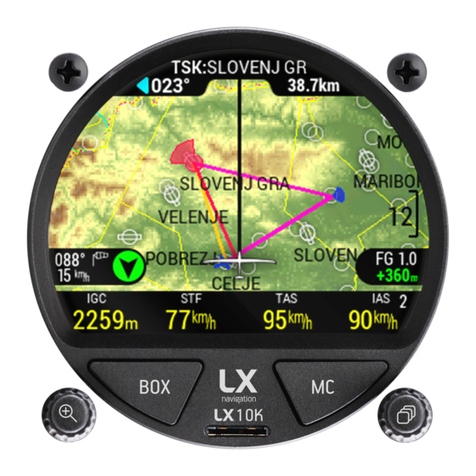
The LX Traffic Monitor has two push buttons and two push/rotary knobs for operation.
The left push/rotary knob, labeled with a magnifying glass, is used for the following operations:
- Turning the device on, when being held for three seconds
- Cancel or Exit, when pressed in most menus
- Zoom level change by turning on navigation pages
Document Name:
Traffic Monitor user’s manual
Version: 1.8
Page 6
- Changing numeric values by tenfold when turning
- Additional info, when pressed while using navigation pages
The right push/rotary knob, labeled with ‘NAVBOX’ icon, is used for the following operations:
- Scrolling between primary pages by turning
- Changing numeric values by one when turning
- Enter or confirm, when pressed in most menus
- Enter submenu, when pressed in primary pages
- Change/edit NavBox, when being held for two seconds in any page that contains a NavBox line
The left button, labeled with ‘BOX’, is used for the following operations:
- Show/Hide and slide between different NavBox lines, when pressed in any page containing a
NavBox line
- Change/edit NavBox, when being held for two seconds
The right button, labeled with ‘VOL’ is used for the following operations:
- Open MC submenu, when on any primary page
- Scroll between options in MC submenu, when pressed
Numeric input
In menus, where numeric input is required, such as Pilot mass or QNH value, the Pilot can either change
the value by 1 with turning the right push/rotary knob, or by 10, with turning the left push/rotary knob.
Alphanumeric input
In menus, where alphanumeric input is required, such as Pilot name and glider type an alphanumeric tape
appears on the left. The pilot can choose the desired letter/number by turning the right push/rotary knob
and confirm or transition to the next character with pressing the push/rotary knob. The left push/rotary
knob has no function here.

Document Name:
Traffic Monitor user’s manual
Version: 1.8
Page 7
Updating procedure
To start the updating procedure, gently eject the micro SD card. Turn off the device. Connect the micro SD
card via the provided adapter or with the card reader to a computer. Open the micro SD card folder. Copy
and paste the file for update (x.xx.lxu) to the root of your micro SD card. Carefully and gently insert the
micro SD card in the LX Traffic Monitor and power up the device.
Go to Setup > Service > Software update and select the desired file. A password input dialog will appear.
Type in the password ‘00000’.

Document Name:
Traffic Monitor user’s manual
Version: 1.8
Page 8
PART TWO – INSTALLATION
1. 2.1 Mechanical installation
LX Traffic Monitor fits in a standard 80 or 57 [mm] // 3.15 or 2.25 [˝] instrument hole so no extra cut out is
required. To fit the LX Traffic Monitor in the instrument panel, unscrew the two mounting screws (black)
with a screwdriver and remove the two rotary knobs.
To remove the rotary knobs do not use force. First, remove the press-in cover to access the screw. Loosen
the screw and pull off the knob. Place the LX Traffic Monitor in the hole in the instrument panel and first
screw in the two black screws and then install the two rotary knobs.
Don’t forget to tighten the screws in the knobs and put the press-in cover back on.
2. 2.2 Electrical installation
FLARM 1 (RJ45) FLARM 2 (RJ45) AUDIO (3.5 mm jack)
Pin number
Description
Pin number
Description
Standard 3.5 mm jack
with audio out
1
Power input
1
Power input
2
Power input
2
Power input
3
Not used
3
Not used
4
GND
4
GND
5
RS 232 data in
5
RS 232 data out
6
RS 232 data out
6
RS 232 data in
7
GND
7
GND
8
GND
8
GND

Document Name:
Traffic Monitor user’s manual
Version: 1.8
Page 9
3. 2.6 Update procedure
In order to update the device, please follow the steps below:
- Find and download the update file on www.lxnavigation.com
- Save the downloaded update file to the root of the supplied microSD card
- Insert the microSD card into the Traffic Monitor
- Turn the device on
- Go to Setup > Service > Software updates and select the downloaded update file
- Type in the password ‘00000’
- Copying of the file, and with it the update process, shall commence
- The device will turn off and require another turn on
- ˝LX updating˝ screen will appear
- After the updating process has ended, the unit will start itself normally. The user should check if
the correct version is displayed on the greeting screen.
4.

Document Name:
Traffic Monitor user’s manual
Version: 1.8
Page 10
6. 2.7 Technical specifications
Traffic monitor 57 Traffic monitor 80
Dimensions [mm] 62.2 x 62.2 x 66.2 82.3 x 82.3 x 68.0
Power supply [V DC] 9.0 - 29.0 9.0 - 29.0
Nominal Voltage [V DC] 13.8
Average power consumption [W] 1.52
Mass [g] 185 255
Mounting panel cut out [mm] 57.0 80.0
Depth behind panel without connectors [mm] 45.5 49.0
Depth in front of panel [mm] 20.7 19.0
Low Ground Survival Temperature [°C] -55
Low Operating Temperature [°C] -20
High Ground Survival Temperature [°C] +85
High Short Time Operating Temperature [°C] +70
High Operating Temperature [°C] +55
Temperature Variation [5°C/min] 5
Relative Humidity [%] 0 – 98
Max. Operational Altitude [ft] 90,000
Operational Shock [10g] 6 g
Crash Safety Shock [20g] 20 g
Vibration DO-160D U F/F1

Document Name:
Traffic Monitor user’s manual
Version: 1.8
Page 11
PART THREE – INTERFACE
3 Primary pages overview
The primary pages represent a row of pages in the graphical user interface, which allow the user to access
different information screens and flight parameters.
The user will go through the following pages, in their respective order, if he swipes to the right:
3.1 Radar page
Usable only when a Flarm and/or ADS-B device is connected. If the Flarm device is not connected, a red
cross will appear. The device is capable of showing all traffic processed by the Flarm (Flarm objects, ADS-B
and Transponder).
NOTE: Press the “BOX” button to hide the parameters bar at the bottom of the display.

Document Name:
Traffic Monitor user’s manual
Version: 1.8
Page 12
Rotating the left push/rotary knob will change the zoom level.
Pressing the left push/rotary knob will open the list of Flarm objects, stating their Flarm ID and aircraft
type, as well as horizontal distance.
Pressing the right push/rotary knob will open the selection option, where the pilot can select an object, for
which additional info will be shown below. The additional info is as follows:
- Vertical speed of the object
- Horizontal distance to object
- Vertical distance to object
- Speed of the object
- Bearing of object
- Current track of object
Pressing the right ‘VOL’ button will open the VOL submenu, where we can see the Flarm, GPS and battery
status indicators, and the following values can be set:
- Volume
- Brightness
NOTE: A red cross across the screen indicates that there is no FLARM connection.
3.2 TP page

Document Name:
Traffic Monitor user’s manual
Version: 1.8
Page 13
In order to use this page to its maximum extent, the user should first import turnpoint, airspace, and
airfield files. For more information on this subject, please refer to Setup/Transfer/Load Turnpoints.
At the top of the screen, the current navigation page is noted with TP, APT or RTE/TSK, followed by the
name of the current navigation point.
In the next line, the steering course is shown on the left and distance to turnpoint on the right.
On the right side of the screen, a scale for zoom level is shown.
In the far bottom a NavBox line containing four NavBoxes is shown. This NavBox line can be manipulated
with the use of the ‘BOX’ button. Pressing the ‘BOX’ button will hide it, for a greater view of the map.
Above the NavBox line, in the middle, a glider (Powered plane for powered aviation) is located with two
lines. The first one, showing in line with the aircrafts chord the current course and the second, toward the
navigation point.
Pressing the left push-rotary knob will open additional info of the point, showing the following info:
- Bearing, indicated with a numeric value and whether or not it is in final glide, with the colour of the
arrow (Red for out of final glade and green for in final glide)
- Distance
- Final glide
- Elevation
Turning the left push-rotary knob will change the current zoom level on the map.

Document Name:
Traffic Monitor user’s manual
Version: 1.8
Page 14
Pressing the right push/rotary knob will open the Turnpoint selection submenu. Here, the pilot can sort
and select turnpoints by distance, name or code. Distance, bearing and whether or not the point is within
range (final glide) is shown for every point.
Pressing the right ‘VOL’ button will open the VOL submenu, where we can see the Flarm, GPS and battery
status indicator, and the following values can be set:
- Volume
- Brightness
NOTE: A red cross across the screen indicates that there is no GPS connection.
3.3 APT page

Document Name:
Traffic Monitor user’s manual
Version: 1.8
Page 15
In order to use this page to its maximum extent, the user should first import airports, airspace, and airfield
files. For more information on this subject, please refer to Setup/Transfer/Load airports.
At the top of the screen, the current navigation page is noted with TP, APT or RTE/TSK, followed by the
name of the current navigation point.
In the next line, the steering course is shown on the left and distance to airports on the right.
On the right side of the screen, a scale for zoom level is shown.
In the far bottom a NavBox line containing four NavBoxes is shown. This NavBox line can be manipulated
with the use of the ‘BOX’ button. Pressing the ‘BOX’ button will hide it, for a greater view of the map.
Above the NavBox line, in the middle, a glider (Powered plane for powered aviation) is located with two
lines. The first one, showing in line with the aircrafts chord the current course and the second, toward the
navigation point.
Pressing the left push-rotary knob will open additional info of the point, showing the following info:
- Bearing, indicated with a numeric value and whether or not it is in final glide, with the colour of the
arrow (Red for out of final glade and green for in final glide)
- Distance
- Final glide
- Elevation
Turning the left push-rotary knob will change the current zoom level on the map.
Pressing the right push/rotary knob will open the Airport selection submenu. Here, the pilot can sort and
select Airport by distance, name or ICAO code. Distance, bearing and whether or not the point is within
range (final glide) is shown for every point.
Pressing the right ‘VOL’ button will open the VOL submenu, where we can see the Flarm, GPS and battery
status indicators, and the following values can be set:
- Volume
- Brightness
NOTE: A red cross across the screen indicates that there is no GPS connection.

Document Name:
Traffic Monitor user’s manual
Version: 1.8
Page 16
3.4 Flarm warning
Appears when the Flarm device sends a warning to its displays. The page itself shows all relevant info to
the pilot with symbols, graphics and numbers.
3.5 Info page
Info page shows the following info:
- current GPS status
- date
- latitude
- longitude
- UTC time
- Voltage of external battery
- Flarm status
- Flarm ID
Pressing the right ‘VOL’ button will open the VOL submenu, where we can see the Flarm, GPS and battery
status indicator, and the following values can be set:
- Volume
- Brightness
3.6 Flight statistics page / Logbook
Flight statistics page appears instead of the logbook page only when the unit is in flight mode.
It shows us our barograph, with time on the x-axis and altitude on the y-axis.
The maximal altitude, flight duration and take-off time are shown.
When not in flight mode, Logbook is shown.
Pressing the right ‘VOL’ button will open the VOL submenu, where we can see the Flarm, GPS and battery
status indicator, and the following values can be set:
- Volume
- Brightness

Document Name:
Traffic Monitor user’s manual
Version: 1.8
Page 17
3.7 Setup page
Under setup, the pilot can set all parameters of the unit. The menus are divided into two subsections, User
and System. User settings are concerning the pilot’s personal preferences, while System settings are
concerned to the device setup. The menus are following:
- User:
o Voice
o Pages
o Graphic
o Transfer
- System
o Units
o NMEA
o Network
o Localization
o Service
o Shutdown
o Exit
3.7.1 Voice
Gives us the option to set volume for Voice commands and which voice commands we wish to hear.
Mixer and Volume for voice warnings can be set, as well as selection of warnings, which should be used by
the voice module.

Document Name:
Traffic Monitor user’s manual
Version: 1.8
Page 18
3.7.2 Pages
The pilot can select which main pages are active. Page is active when the box is checked. There are eight
main pages available:
- Flarm
- TP page (turnpoint)
- APT page (airport)
- RTE/TSK page (route/task)
- GPS Info
3.7.3 Graphic

Document Name:
Traffic Monitor user’s manual
Version: 1.8
Page 19
The Graphic setup is where you can set custom colours for Airspace, Map and Task, as well as set font sizes
for map objects. By selecting Theme you can either select “Black panel” for black background or “White
Panel” for white background.
Airspace
In the Airspace menu you following submenus to edit:
- Controlled Zone
- Prohibited
- Restricted
- Danger
- Terminal area
- Airway
- Glider
- Military
- Other
- Class A, B
- Class C
- Class D
- Class E
- Class F
Under each submenu you can find Outline and Fill row. Some have only Outline. By selecting each row you
enter the menu with a scroll bar for selecting the colour. As described in point 1.4 Basic use & gestures.
Once you have adjusted the colour you want to use, press back on the top left corner of the display and
the settings will be saved and you will return to the submenu.
The same logic applies to set colour for Fill.
This manual suits for next models
1
Table of contents
Other LX Navigation GPS manuals

LX Navigation
LX Navigation Iris Series User manual

LX Navigation
LX Navigation LX10K User manual

LX Navigation
LX Navigation LX5000 V9.0 User manual

LX Navigation
LX Navigation LX8000 User manual

LX Navigation
LX Navigation Colibri User manual

LX Navigation
LX Navigation LX Mini Map User manual

LX Navigation
LX Navigation Zeus User manual

LX Navigation
LX Navigation LX 5000 User manual

LX Navigation
LX Navigation LX Eos 57 User manual