manuals.online logo
Brands
  1. Home
  2. •
  3. Brands
  4. •
  5. Lynteck
  6. •
  7. Floodlight
  8. •
  9. Lynteck TITAN TF20WLED User manual

Lynteck TITAN TF20WLED User manual

TITAN
10W x2LED FLOODLIGHT
•LED lampheads
‚Wall mount / terminalblock
ƒPIRdetector
INTRODUCTION
The Titan twinhead 20WLEDFloodlightoffers youan
economical lighting solutionwithextremelylowenergy
consumption.
During darkness,the built-in passiveinfrared (PIR)
sensorturnson the Floodlightwhen the PIRsensor
detectsamoving heatsourcein itscoveragearea.During
daylight, the built-in photocell sensorsavesenergyby
deactivating the Floodlight.
Note:Pleaseread thisentire manualbeforeyou start
installation.
SAFETYPRECAUTIONS
lDONOTinstall whenit israining.
lIsolatethe powersupply beforeinstallation.
lUK Building Regulationsrequireoutdoormains
installationsbecarriedout by aqualifiedelectrician.
lBS7671: 2008IEE Wiring Regulationsmust be
complied within all respects.
lHO5RNFround flexible cable anddrip loopsmustbe
usedtoavoidwateringressdamage tothe unit.
lEnsurethat the powersupply isprotected by a6A
circuit breakerorsuitablefuse.
lEnsureminimum distanceof0.5m away from lighted
objects.
lThe unitmustbe installedvertically(FIGURE1a)
NOThorizontally (FIGURE1b).
VERTICALHORIZONTAL
FIGURE 1a FIGURE 1b
CHOOSINGAMOUNTING LOCATION
lForthe bestresults,mountthe Floodlightonto
normal brickwork2.5m abovethe ground.
lAvoid aiming the PIR sensor atpools,heating vents,
airconditionersorobjectsthatmaychange
temperature.
lAvoid pointingthe PIRsensorattreesorshrubsor
wherethe movementofpetsoranimalsmaybe
detected.
lAvoid locationswheredirectsunlightwillshine onto
the frontofthe PIRsensorforlong periods,
deteriorationofthe Fresnellensmayoccurleading
topoortriggering response.
lPriortomounting,keep in mind thatthe PIRsensor
ismoresensitivetoaheatsourcemovingacrossits
coverage areaand lesssensitivetoaheatsource
thatmovesdirectlytowardsthePIRsensor
(FIGURE 2).
FIGURE 2
Select alocation forthe unit based onthe coverage
anglesshownin FIGURE 3.
180¢X
1 2 m
110¢X
COVERAGEANGLES
FIGURE 3
•
‚
ƒ
•
2m
2.5m
180
°
1
10
°
WIRINGINSTRUCTION
(1)WARNINGisolatethe powersupply.Aninternal
singlepole wall switchisrecommendedtoallow
easy control of the floodlight.
(2)Detachthe wall box by unscrewingthe screw
adjacent tothe control knobs(retainthe screwfor
lateruse). (FIGURE 4)
FIGURE 4
(3)Useabraddletopunchasmall holein the cable
grommet, enabling the supply cabletoenterthe wall
box.
(4)Routethe supply cablethrough the cablegrommet.
Adrip loop isrequiredbetween the wall box and the
wall toavoid wateringress.
(5)Determine the correctlocationtomountthe
floodlight. Usethe wall boxasatemplatetomark
the fixing holesonthe wall.Drill the holesand insert
the plasticwall plugssupplied.Fixthe wall boxusing
the screws provided. (FIGURE 5)
m
5
.
38 m
FIGURE 5
(6)Strip approximately6-8mmofinnercoreinsulation
from the supply cable.
(7)Connect the BROWN wire(Livewire)tothe terminal
marked “L”.
Connectthe BLUEwire(Neutral wire)tothe terminal
marked “N”. (FIGURE 6)
NB: The floodlight isdoubleinsulatedno earthis
required.
TOLAMP LIVE
NEUTRAL
AC POWER
BROWN
BLUE
FIGURE 6
(8)Locateand mountthe Floodlightontothe wall box
and securewiththe retaining screw(DONOTover
tighten).
ANGLEADJUSTMENTS
The LEDLamp Headscanbe adjusted45° leftand45°
right; the PIRsensorcanbe adjusted90° leftand90°
right. (FIGURE 7a)
RIGHT 45¢X
LEFT 45¢X
RIGHT 90¢X
LEFT 90¢X
FIGURE 7a
The LEDLamp Headscanbe tilted 37.5° down.ThePIR
sensorhasanadjustmentslideron the rearofthe unit.
Thissliderisusedtotiltthe angleofPIRsensordownto
30° maximum. (FIGURE 7b)
30¢X
37.5¢X
adjustment
FIGURE 7b
Adjustment
Slider
LEFT45°RIGHT45°
LEFT90°RIGHT90°
37.5°
30°
NEUTRAL
LIVE (VIA WALL SWITCH)
SUPPLY CABLE
SETTING THE LIGHTING SYSTEM
(1)TESTMODE
lTurnthe LUXcontroland the TIMEcontrol
counterclockwisetothe TESTposition.(FIGURE 8)
Time
5S 12min
Lux
FIGURE 8
lTurnon the wall switch.The unitwill startwarmup
sequenceforabout 60 seconds. Afterwarmup it will
automaticallyreverttoautomaticoperation.During
the warm-upperiodthe lightswill stay on.
lWalkthroughthe detectionarea.Thelightsturnon
whenyou moveand turnoffwhen youstop.Wait
until the lightsturnoffandthen moveagain totest
the sensor.
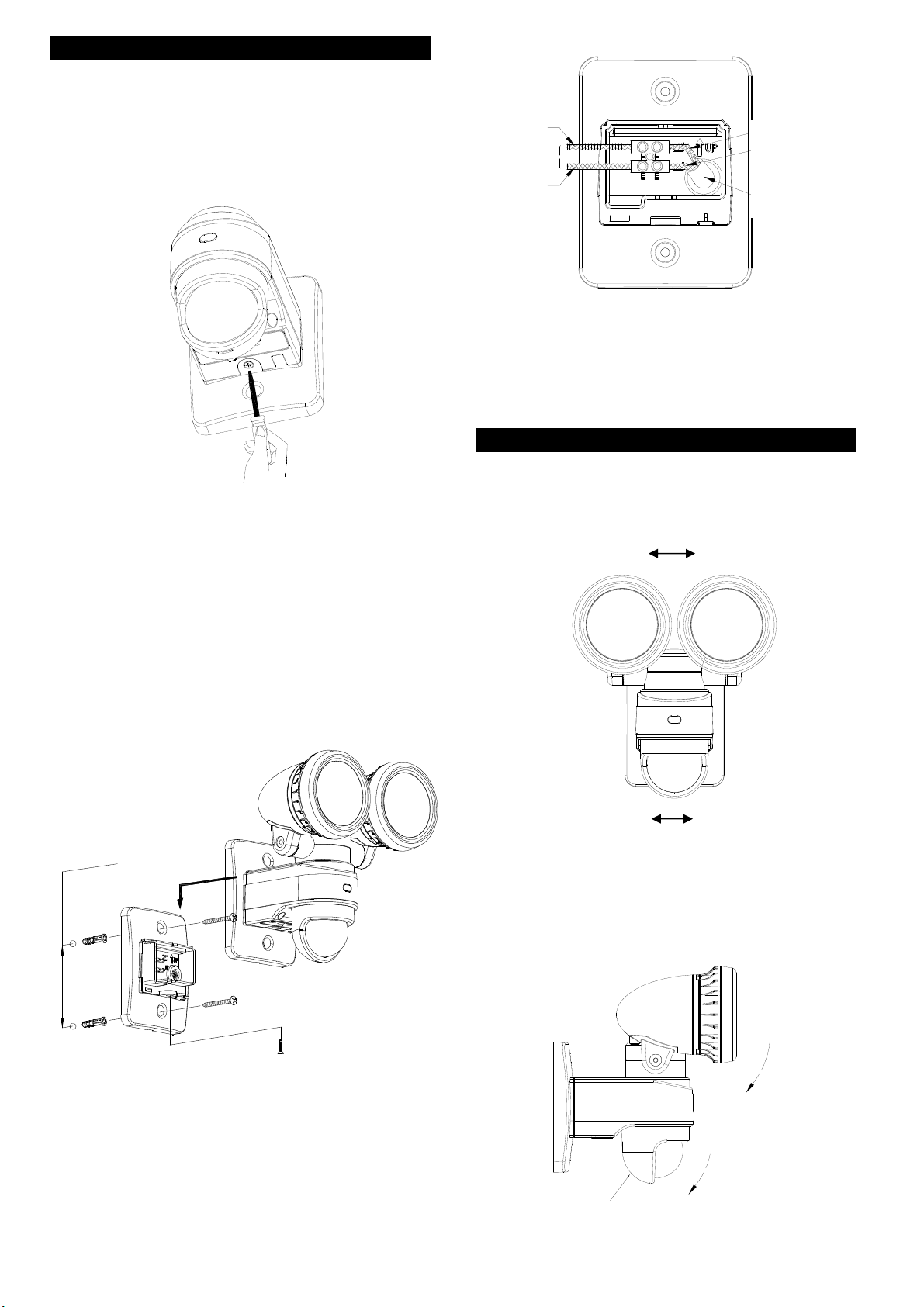
lAdjustthe motion sensortocover the desired
detectionarea.Forasmallercoveragearea,tiltthe
sensordown; foralargercoverage area,tiltthe
sensorup.
(2)TIMEADJUSTMENT
The TIMEadjustmentcontrolshowlongthe lightwill stay
on aftermotionhasbeen detected.
Turnthe TIMEcontrol clockwisetoincrease(up to12
minutes)thetime the lightsstayonfororcounter
clockwisetodecrease(downto5seconds)the time the
lightsstay on for. (FIGURE9).
Time
5S 12min
Time
5S 12min
FIGURE 9
(3)LUXADJUSTMENT
The LUXcontrol determinesthe ambientLuxlevel the
lightswill turnon when the sensor isin automatic
operation.
The Luxlevel can be setbetween30 and200 Lux. Turn
the LUXcontrol clockwisetothe MOONposition and the
lightswill onlyturnon atnight(below30 Lux).Turnthe
LUXcontrol knobcounterclockwisetoincreasethe Lux
setting.Setthe controltosuityourrequirements.
(FIGURE 10)
Lux
FIGURE 10
OPERATION
Dependingon yourrequirementsyou can switchthe unit
between the following operation modes:Automatic
Operation andManual Override.
(1)AutomaticOperation
Turnon the wall switch.Afterabout60 secondswarmup
the PIRsensorwill enterautomaticoperation.Whenthe
PIRsensordetectsamoving heatsourceand the
ambientlightlevel islowerthan the LUXsetting,the light
will automaticallyturnon.The lightwill stayon forthe
durationofthe TIMEsetting and then turnoff. Notethatif
anothermoving heatsourceisdetectedwhile the lightis
still on, the timerwill restart.
(2)Manual Override
Tokeep thelighton regardlessyou can override the
automaticoperation.Toenable manualoverride mode,
firstensurethatthe lightison and then turnthe wall
switchoffandon twice(off-on,off-on)within 3seconds.
The interval betweeneachoperation mustbe 0.5to0.75
seconds.
InManual Overridemode,the lightwill remain onfor
around 5hours.After5hours thelightwill turnoff andthe
motion sensorwill revert toautomaticoperation.
You can alsomanuallysetthe motion sensorbackto
automaticoperation byturning offthe wall switchforat
least 10 secondsand then turning it backon.
TROUBLESHOOTING
Lightsdo notturnon
lMakesurethewiringconnection iscorrect.
lEnsurethat you arewithin detectionrange.Adjust
the PIRsensorangleif necessary.
lAdjust the LUX control knobby turning it
counterclockwise.
Lightsremainon
lMakesurethewiringconnection iscorrect.
lAdjust the TIME control knob by turning it
counterclockwise.
lMakesurethat the unit isnot in ManualOverride
mode.
Others
lCheckwithyourelectricianwho did the installation.
SPECIFICATIONS
*
PowerRequirement AC220 -240V / 50Hz
Lighting Load 20W(10Wx 2)LED
ColorTemperature(K) 5000K
CRI >70
Lumen (lm) Upto1100lm(550lm x 2)
L70 LifeSpan (hours) Upto30000 hr
Detection Angle Upto180°at 2.5m Height
Detection Range Upto12m at2.5m Height
Projection Area 7m
2
PIRSensorAdjustment
Angles
Upto90° Left
Upto90° Right
Upto30° Down
LEDHeadsAdjustment
Angles
Upto45
o
Left
Upto45° Right
Upto37.5° Down
Mounting Height Recommended 2.5m Brick
Wall Mount
Time Adjustment 5seconds-12minutes
LuxAdjustment 30 -200 Lux
Operation Mode Auto/Manual override
WarmUpTime About 60 seconds
WorkingTemperature -20
°
Cto+40
°
C
Dimension 201 x 185 x 167(mm)
ProtectionClass Class II Double Insulated
IPProtection IP44
Safety CE
*Specifications are subject to change without notice.
TITANTF20WLED 2014/03
Environmental Concerns:
PleaseDONOTdisposeofelectrical appliancesas
unsorted waste,usethe recycling facilitiesprovidedby
yourlocal authorities.
PleaseDONOTdisposeofpackaging as unsorted waste,
usethe recycling facilitiesprovidedbyyourlocal
authorities.

Other Lynteck Floodlight manuals

Lynteck TITAN TRS21TX User manual

Lynteck

Lynteck TITAN TRS21TX User manual

Lynteck SA122 User manual

Lynteck

Lynteck SA122 User manual

Popular Floodlight manuals by other brands

Claypaky GOLDEN SCAN 4 instruction manual

Claypaky

Claypaky GOLDEN SCAN 4 instruction manual

Night Watcher nw1003X Installation & operating manual

Night Watcher

Night Watcher nw1003X Installation & operating manual

Esseci TERES Assembly instructions

Esseci

Esseci TERES Assembly instructions

ICON STAGE user manual

ICON

ICON STAGE user manual

Show Tec compact par 7 MKII user manual

Show Tec

Show Tec compact par 7 MKII user manual

JB Systems Light Dynamo Operation manual

JB Systems Light

JB Systems Light Dynamo Operation manual

CO/Tech 36-4137 Original instructions

CO/Tech

CO/Tech 36-4137 Original instructions

Timeguard LED88PIR Installation & operating instructions

Timeguard

Timeguard LED88PIR Installation & operating instructions

superbrightleds FLSC Series user manual

superbrightleds

superbrightleds FLSC Series user manual

MegaLite Drama FS-LED 700 user manual

MegaLite

MegaLite Drama FS-LED 700 user manual

Magicfx FLAMEBLAZER User and installation manual

Magicfx

Magicfx FLAMEBLAZER User and installation manual

Chauvet Line Dancer CH-300 user guide

Chauvet

Chauvet Line Dancer CH-300 user guide

CO/Tech IPC15A1A quick start guide

CO/Tech

CO/Tech IPC15A1A quick start guide

Timeguard LED100PIRBP Installation & operating instructions

Timeguard

Timeguard LED100PIRBP Installation & operating instructions

Timeguard LEDPRO10WH Installation & operation instructions

Timeguard

Timeguard LEDPRO10WH Installation & operation instructions

HQ Power VDPLP64SLB user manual

HQ Power

HQ Power VDPLP64SLB user manual

chinavasion CVXR-S60 Operation instructions

chinavasion

chinavasion CVXR-S60 Operation instructions

DeWalt DC509-XE instruction manual

DeWalt

DeWalt DC509-XE instruction manual

manuals.online logo
manuals.online logoBrands
  • About & Mission
  • Contact us
  • Privacy Policy
  • Terms and Conditions

Copyright 2025 Manuals.Online. All Rights Reserved.