TIMEADJUSTMENT
The TIME adjustment(located atthe bottomof the PIRsensor) controlshowlong the transmitterfloodlight isoperational
afterbeing triggered byitsPIRsensor.The timerwill turnon the floodlightstransmitter(and the lampcontained inthe
floodlight unless overridden byitsLUXadjustment control)forthe duration set on the TIME adjustment control.
The TIME setting isadjustablefrom5secondsto12 minutes(FIGURE19).Setthe
timeaccording toyourpersonalrequirements.
FIGURE19
TRSreceiver(s)coded tothe floodlightwill alsoactivateand remainon forthe sameduration (unless overridden bytheir
LUXadjustment control).
LUXADJUSTMENT
The LUXadjustment(located atthe bottomofthe PIRsensor) determinesat what light levelthe transmitterfloodlight will
start operating.
Provisionallyturnthe LUXcontrolfullyclockwisetothe moon symbol(dusk) position
(FIGURE20).Atthisprovisionalsetting the floodlightremainsinactiveduring daylight, but
the floodlight PIRsensorand transmitterremainactive.Atduskthe floodlightwill become
active.Ifthisprovisionalsetting provestobe unsuitablethe LUXcontrolshouldbe
adjusted.Simplysetthe LUXcontroltothe position you desirethe floodlighttobecome
activeasdaylight declines.
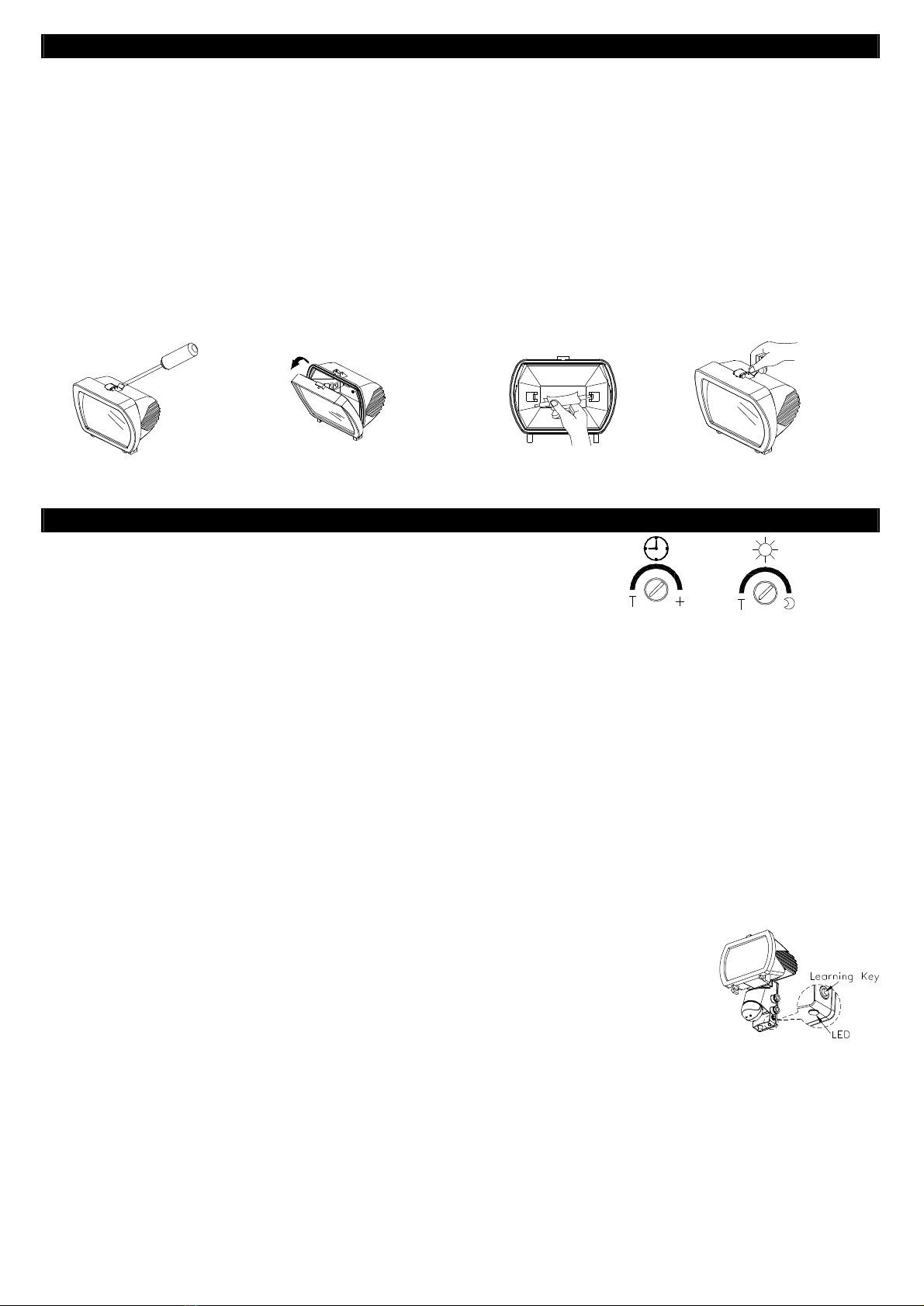
AUTOMATICCIRCUIT TEST
The transmitterfloodlighthasan automatic circuittest. Thisisusefulif you experienceproblemscoding TRSreceiver(s)
orsuspect aproblemwiththe transmitterfloodlightcircuitry orwiring.ToactivateAUTOMATICCIRCUIT TESTpress and
releaseimmediatelythe Learning Key(FIGURE18).The led indicatorwill flashthree timesand the floodlightwill
illuminateand remainon until you againpress and immediatelyreleasethe Learning Key.Ifthe transmitterfloodlight
functionscorrectlyduring thistest lookelsewhereforthe problem.
TROUBLESHOOTING
Floodlight doesnot turnon:
l Check ifthe wall switchisturned on.
l Confirmthat you havemade the correct wiring
connections.
l Makesurethat the lamphasnot burned out.
l Carry out automaticcircuit test.
PIRsensornot working:
l Check ifthe wall switchisturned on.
l Confirmthat you havemade the correct wiring
connections.
l Ensurethat the PIRdetectorisnot mounted
aboveorclosetoaheat sourceand not subject
tobright sunlight during daylight hours.
l Carry out automaticcircuit test.
TRSreceiversnot responding:
l Check ifall wall switch(s)areturned on.
l Check ifreceiverLUXsettingsareoverriding.
l Makesureall wiring connectionsarecorrect.
l Carry out automaticcircuit test.
Environmental Concerns:
PleaseDONOT disposeofelectricalappliancesasunsorted waste,usethe recycling facilitiesprovided byyourlocal
authorities.
PleaseDO NOT disposeofpackaging asunsorted waste, usethe recycling facilitiesprovided byyourlocalauthorities.
Page 4of4
PowerRequirement AC230/240v50Hz
THLampLoad Max. 500WTHHalogen Lamp
AdditionalLighting Load 1000WIncandescent
TransmitterFrequency 433MHz
Transmission Range Approx70m(inopen space)
Detection Angle Up to110°at 25°C
Detection Distance Up to12m(39.3ft)at 25°C
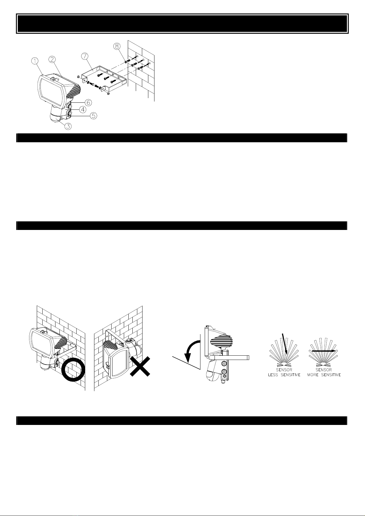
Mounting Height Recommended 1.8-2.4m
(5.9-7.8ft)SolidWall Mount
Wall SwitchControl On/Off
Learning Key Code learning &automatic
circuit test
TimeAdjustment 5seconds-12 minutes
LuxAdjustment 5-200 lux
WarmUp Time Approximately1minute
IndexofProtection IP44
Specificationssubjectto changewithoutnotice.
FIGURE20