P DM 5240 Reference Manual. Rev 2.1
Page 2 of 30
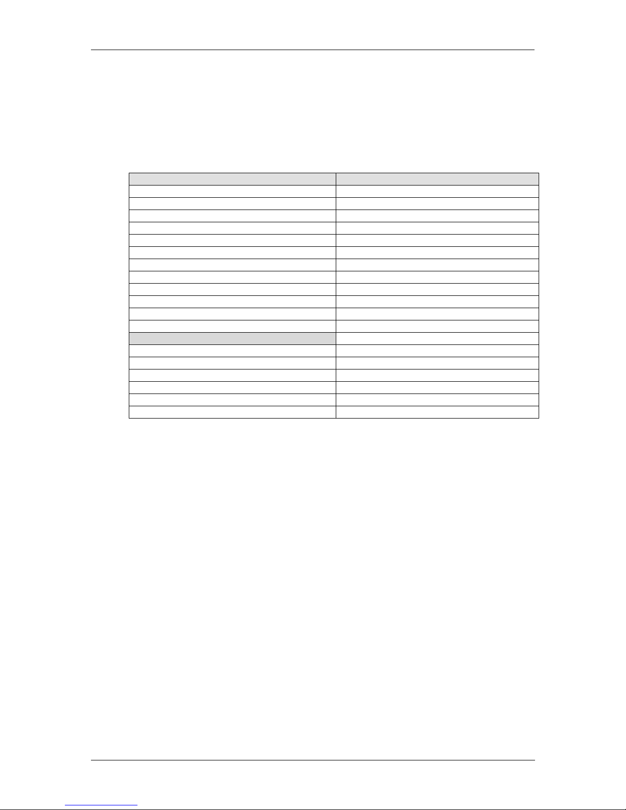
Contents
Contents...............................................................................................................2
Warranty...............................................................................................................4
Regulatory information ........................................................................................5
Europe......................................................................................................................................... 5
Declaration of Conformity ....................................................................................................... 5
USA............................................................................................................................................. 5
FCC 47 Part 15....................................................................................................................... 5
Getting Started.....................................................................................................6
Packaging.................................................................................................................................... 6
ESD Warning............................................................................................................................... 6
Preventing ESD Damage........................................................................................................ 6
Caution.................................................................................................................................... 6
Product Description .............................................................................................7
Key Features............................................................................................................................... 7
Video Input Formats.................................................................................................................... 8
Video Output Formats................................................................................................................. 8
Audio Processing ........................................................................................................................ 9
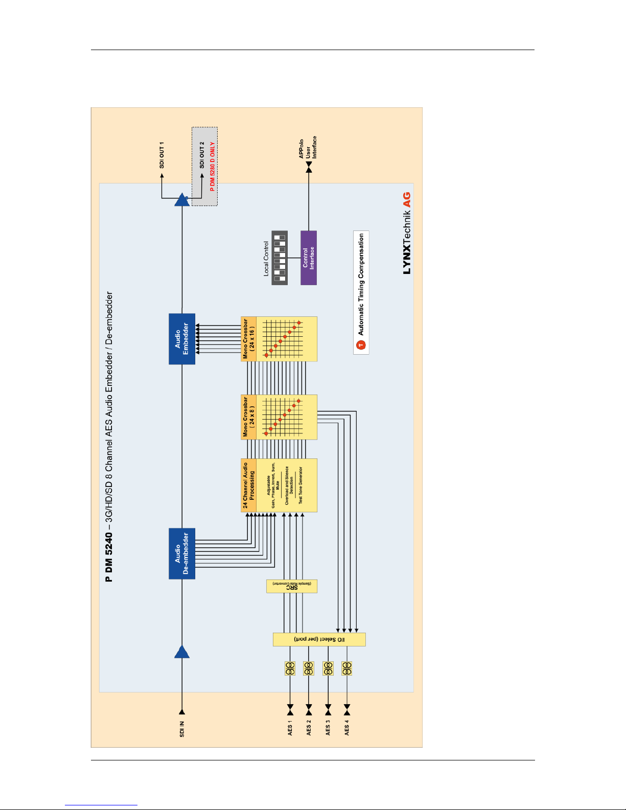
Functional Diagram................................................................................................................... 10
Module Layout........................................................................................................................... 11
Connections .......................................................................................................12
Video......................................................................................................................................... 12
Audio......................................................................................................................................... 12
Installation .........................................................................................................13
Settings and Control ..........................................................................................13
DIP Switch Settings................................................................................................................... 14
Factory Preset Condition ...................................................................................................... 15
Auto Store............................................................................................................................. 15
Reset Button ......................................................................................................................... 15
Alarm/LED Status Indicators..................................................................................................... 16
LED 1: SDI Status................................................................................................................. 16
LED 2: Audio Status.............................................................................................................. 16
Alarm LED............................................................................................................................. 16
Power LEDs.......................................................................................................................... 16
Local/Remote LED................................................................................................................ 16
Control System GUI............................................................................................17
Overview ................................................................................................................................... 18
Video Path ............................................................................................................................ 18
Audio Routing ....................................................................................................................... 18
flexGUI path highlighting and signal patching....................................................................... 19
Timing and Delays..................................................................................................................... 19
Audio Infastructure.................................................................................................................... 19
Audio Content Detection....................................................................................................... 20