SDI Present LED
= Valid SDI Signal connected
= (out) Non valid SDI signal or signal missing
REF Status LED
REF Input is bi-level or tri-level analog sync (auto detect), and will cross lock and convert the
SDI output to the REF standard if there is a“mismatch” between the SDI in and REF.
= REF is present and matches the SDI input format
= REF is present but does not match the SDI input format. The SDI
output is being converted to match REF input standard
= (out) REF signal is not present / valid
Power / Status LED
= Power OK, and no internal programmed settings are present
= Power OK, and some internal programmed settings are active*
= Power OK, but the module switch settings have been overwritten
with the yelloGUI application. (Manual operation of any local switch
will revert module back to the physical switch settings, and will change
LED status back to yellow or green).
= (out) Power not present
* Some additional internal settings have been made using yelloGUI and the
LED indicates this by turning yellow. The module can be reset to factory default
using the yelloGUI application, or by using the reset switch on the side of the
module, which can be accessed though a hole with a paper-clip (or similar).
yellobrik
®
LYNXTechnik AG www.lynx-technik.com
I/O Connections
All connections are clearly indicated on the module. Electrical SDI and
REF IN connections are made using standard 75 Ohm BNC connectors.
GPI Connections
The module supports 4 external GPI connections, these are contact
closure connections and are made using a standard RJ45 connector.
Connection details below.
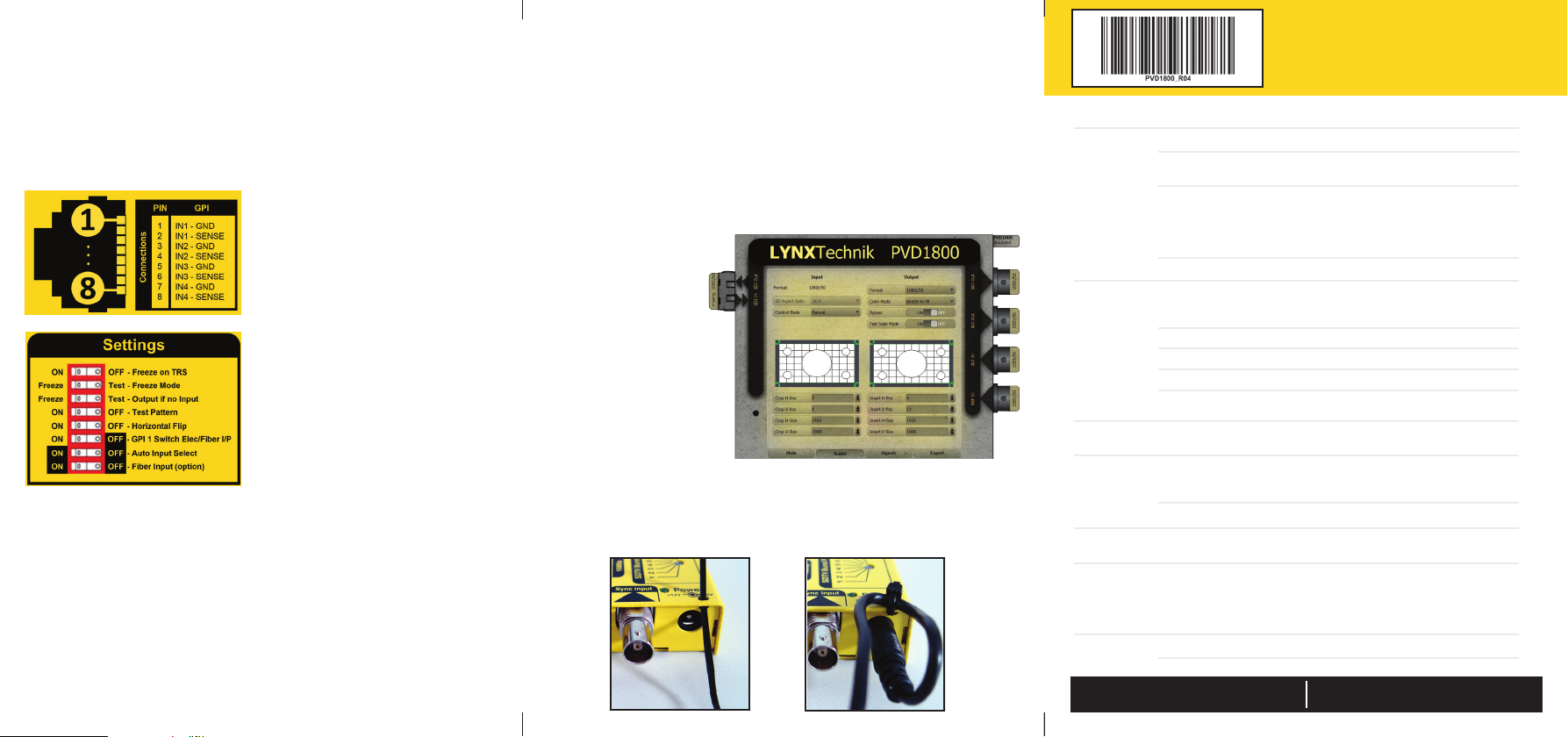
Settings
A dip switch is provided for module
conguration.
Each switch function is described
below.
Technical Specifications
SDI Input 1 x 75 Ohm BNC electrical SDI input + 1 x optional fiber SDI input
Serial digital video SMPTE, 292M, 424M, 259M with automatic video
format and standard detection
SMPTE 424M, SMPTE 292M, SMPTE 259M
3G Level A & B-DL & B-DS according to SMPTE ST 425-1 with image formats
1280 x 720 and 1920 x 1080
For a detailed list of supported formats please refer to the article in our knowledge base
(www.lynx-technik.com > support > tech.support)
Electrical Return Loss: >15dB from 5MHz to 1.5GHz, >10dB from 1.5GHz to 3GHz
SDI Outputs 2 x 75 Ohm BNC electrical SDI outputs. SMPTE, 292M, 424M, 259M
1 x optional fiber SDI output
Output follows input format
Electrical Return Loss: >15dB from 5MHz to 1.5GHz, >10dB from 1.5GHz to 3GHz
Timing Jitter: <0.2 UI @ 270Mbit/s, <1.0 UI @ 1.5Gbit/s, <2.0 UI @ 3Gbit/s
Alignment Jitter: <0.2 UI @ 270Mbit/s, <0.2 UI @ 1.5Gbit/s, <0.3 UI @ 3Gbit/s
Automatic cable EQ (Belden 1694A cable)
340m @ 270Mbit/s, 150m @ 1.5Gbit/s, 110m @ 3Gbit/s
Fiber I/O Optional plug in SFP for optical SDI I/O (see fiber options table)
SMPTE 297M - 2006
Reference
Input
SDTV: Analog 525 or 625 bi-level sync
HDTV: All tri-level sync standards (exceptions 1080p 50/59.94/60Hz)
Cross lock compatible
SMPTE 274M, SMPTE 296M - 75 Ohm BNC connector
Video Delay Timing Adjustment: Up to 30 frames.
Manually adjustable in frame / line / pixel increments
GPI Connector RJ45 with 4 x External GPI inputs:
GPI 1 is used for Electrical / Optical SDI changeover
GPI 2 is used for force a “freeze” of the signal
GPI 3 is used to enable the “latched” changeover mode
Power +12VDC @ 5.8W nominal (without SFP) - (supports 7 - 24VDC input range)
Note. The depiction of the RJ45
connector and pin numbering is
made looking into the female
connector on the module.
Function description see technical
specications table.
1 = Freeze on TRS - When set to ON the SDI output will “freeze” when a TRS error
is detected on the SDI input
2 = Freeze Mode - Sets the freeze output to be the video image or test pattern
3= Output if no input - Sets what the SDI output is when there is no input signal
4 = Test Pattern - Turns the test pattern generator ON or OFF
5 = H-Flip - Flips the SDI output horizontally
6 = GPI Switch Inputs - When set to ON - GPI 1 will switch the SDI input between
electrical (GPI open) and Fiber (GPI closed) - this switch overrides the next
two switch settings
7 = Auto Input Select - If the main input is lost then the module automatically
switches to the other SDI input. The “main”input is determined by the
setting of the next dip switch
8 = Fiber Input - Switch SDI input between Electrical (OFF) and ber (ON)
Power Lead Strain Relief
The module has a small hole in the case located above the power
connection. To prevent the power lead being accidentally pulled out,
use the supplied tie-wrap and secure the lead as shown below.
GPI 4 is used to disable the “latched” changeover mode
Converter and Scaler Adjustment
Connect the PVD 1800 with a USB cable to a computer (PC or Mac)
USB Port
The USB port is used for rmware updates and for PC/MAC control using
the yelloGUI software. Download yelloGUI from our website:
www.lynx-technik.com > support > downloads > yelloGUI software
Firmware updates are always provided free of charge and are available
via the yelloGUI.
running the yelloGUI
control software.
The module will
automatically be
detected.
Select the “Scaler” tab to
access the converter
and scaler settings.
All settings set in the
yelloGUI will be
automatically stored to
the module.


