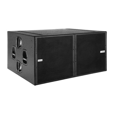
Lynx CLS-212 User manual

USER MANUAL
V.21.01
Lynx Pro Audio S.L.
CLS-212
CLS-121S
CLS-218S

Manufacturer
CE CERTIFICACTION, EUROPEAN PRODUCT
CLS-212
LYNX Pro Audio S.L.
Calle 1 - Pol. Ind. Picassent
E-46220 Picassent (Valencia)
This user guide is property of Lynx Pro Audio S.L. Any reproduction of this manual, by any means is strictly prohibited.
Copyright 2020. All rights reserved.
CLS-121S
CLS-218S

CLS Series User Manual
Lynx Pro Audio S.L www.lynxproaudio.com 3
INTRODUCTION
This manual describes the recommended installation procedure for the Coaxial Line Source cabinets CLS-212 in
combination with the subwoofers CLS-121S and CLS-218S.
The CLS series is Lynx Pro Audio’s answer to scalable line array systems.
Extreme care has been taken to select and customize the most advanced components on the market, including coaxial
Mid/high drivers together with full electronic synergy through the coupling of the system amplication & integrated
DSP technology.
Total system control is also achieved through our 3D prediction software (Rainbow 3D) working together with our
remote system management platform (OCS). These cutting edge softwares together with the CLS technology provides
the most optimum and precise listening experience to every ear in the audience.
CONTENTS
• SAFETY PRECAUTIONS 4
• SYSTEM OVERVIEW
CLS-212 5
CLS-121S 7
CLS-218S 9
BACK PANEL 11
CONNECTORS AND CONNECTIONS 13
• CONFIGURING THE DIGITAL SIGNAL PROCESSOR
FIR FILTERS 15
CONFIGURING THE DSP OPTIONS 15
CONFIGURATION PANEL 15
• ONLINE CONTROL SYSTEM 17
• RAINBOW 3D ACOUSTIC SIMULATION SOFTWARE 18
• HARDWARE AND ACCESSORIES 19
• CLS-212 RIGGING HARDWARE 20
• CLS-212 HOW TO FIX CABINETS 21
• HOW TO USE THE FLYING FRAME ON CLS-212 23
• CLS-212S RIGGING HARDWARE 28
• HOW TO USE THE FLYING FRAME ON CLS-212S 29
• FLOWN CONFIGURATION ON CLS-121S 30
• STACK CONFIGURATION ON CLS-121S 34
• APPLICATION EXAMPLES FOR CLS-121S 39
• APPLICATION EXAMPLES FOR CLS-218S 40
• CERTIFICATIONS AND GUARANTEE 44

CLS Series User Manual
Lynx Pro Audio S.L www.lynxproaudio.com 4
Before starting to use this device, please read this instruction manual carefully.
Keep these instructions in the place where the equipment will be used and with easy access to them.
• Electrical appliance
The exclamation mark within a triangle identies the presence of electricity. Use the system carefully without wet
hands or feet. Avoid installing the speaker in wet or excesivelly humid places. Do not place material that contains
liquid on or near the unit. Avoid dripping or splashing water or any liquid over the unit. Regularly check the condition
of the cables and make sure these are not being walked on or pinched. Connect the speaker to bipolar, earthed
mains. The mains plug must be connected to the appropriate protection (fuse or breaker). Connection to any other
type of mains could result in an electrical shock and violate local electrical codes.
CAUTION: DO NOT CONNECT OR DISCONNECT THE AC POWER CONNECTORS UNDER LOAD.
•Heavy equipment
Apply back protection when using the system. Avoid loading and unloading at heights.
•Electrical shock risk
The diagonal mark within a triangle identies the presence of dangerous voltage.
Do not open or handle the interior of the box. These parts are not to be adjusted by the user. For maintenance and/
or repair please go to an authorized service centre.In order to reduce the risk of electric shock, disconnect from
AC before plug in or unplugging Audio signal cables. Reconnect to AC only if all signal connections are made and
secured. Never manipulate the ground type plug provided.
The AC mains plugs should always remain accessible for operation.
Unplug the loudspeaker during storms or when it’s being used for a long time.
•Hearing damage risk
These systems can reproduce large quantities of sound pressure which can damage hearing. Take precautions if
you are going to be near them for extended amounts of time and do not get too close.
•Hanging / Flying
Do not hang the cabinets from the handles or from any other part other than the designated hanging point. When
ying this system please observe the technical and “Rainbow” software data carefully. Never exceed the maximum
safe working loads or ignore the instructions included within this manual. Use Only ying accessories provided by
Lynx Pro Audio S.L. Rigging must be always carried out by professionals.
•Delicate Material
Please ensure no foreign object or water enters the speaker. Only clean the unit with dry cloths. Do not use solvents.
•Overheating / Fire risk
To reduce the risk of the speaker over heating, avoid direct contact with sunlight. Avoid placing the unit close to heat
inducing objects such as radiators. Do not cover the equipment in use and do not block any ventilation openings.
Do not put naked ame, such as lighted candles, close or on top of the unit.
•Electromagnetic and interferente emissions
Avoid placing objects which through electromagnetic waves can damage the unit, such as mobile phones, lap tops,
magnetic strip cards etc.
This system complies with normatives EN 55103-1 (1)
EN 55103-2 (2)
(1) This device may not cause harmful interferences.
(2) This device may receive interference including interferences that may cause undesired working.
•IMPORTANT NOTE
This Equipment must be used in accordance with these instructions and by trained professional personnel only.
This equipment should not be used in places with extreme tropical climates. Don’t expose this apparatus to extreme
humidity and or temperature values.
CLS Series User Manual
Lynx Pro Audio S.L www.lynxproaudio.com 5
SYSTEM OVERVIEW
• Technical Data:
Frequency range: 60 Hz - 22 KHz ( - 6 dB)
Horizontal coverage: 100º
Vertical coverage: Single element 10º
Max SPL / Peak: 142 dB / 148 dB
Components:
• LF: 2 x 12”. 4” DUO double layer in/out copper voice coil,
waterproof cone treated on both sides, neodymium magnet. 1400 W (AES)
• MF/HF: 8” dual diaphragm coaxial planar wave driver.
- Mid: 3.5” (90 mm) voice coil, 150 W (AES)
- High: 1.5” (44.4 mm) voice coil, 80 W (AES)
Power amplier: 2800W Class D with switching power supply & PFC
LF amplier:1 x 1400W
MF/ HF amplier:1 x 1400W
DSP: Internal Lynx Processor DSPB-FL. 96 KHz / 64 bit double-precision, DSP
with FIR lter linear phase.High performance 32 bit 96 KHz AD/DA
converters 120dB
Crossover: Digital, FIR lter 550Hz
Passive, 6.3 KHz
Control: User control interface with 2.8” IPS and multifunction joystick controller
Control connections: USB (DSP programming)
Dual Ethernet port, Online Control System
Input: BAL/ UNBAL XLR connectors analog input
AES/EBU digital input optional
Nominal voltage: 100 - 240V AC @ 50-60 Hz
Operating voltage: 85 - 264V AC
AC Connectors: 16A Neutrik powercon true1 TOP with looping output
Finish: Polyurea coating, high grade resistant paint
Material: 15 mm Premium birch plywood
Dimensions: 254.5 x 600 x 480 mm (H x W x D) / with pins 613.5 mm (W)
Weight: 47 Kg (103.6 lbs)
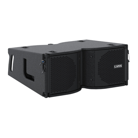
•CLS-212
Extremely compact & extremely powerful 3-way, self-powered (6000 W Class-D with PFC), DSP
integrated coaxial line array element. Dual high power 12” neodymium transducers and two unique 6.5”
dual diaphragm coaxial planar wave driver.
•Key features
• Extraordinary power-to-size ratio
• Unique 6.5” dual diaphragm planar wave driver
• Perfect acoustical coupling of individual units providing continuous line source & excellent phase coherence
• Extended bandwith (65 Hz – 22 KHz)
• Integrated Digital processor (64 bit / 96 KHz) with FIR linear phase ltering
• Perfect Time Alignment avoiding Multi-Source Interference problems
• Ergonomic design in premium birch plywood & nished in polyurea
• 2.8” IPS display with multifunction joystick control

CLS Series User Manual
Lynx Pro Audio S.L www.lynxproaudio.com 6
• CLS-212 measurements
815.5
800
480
384
10º

CLS Series User Manual
Lynx Pro Audio S.L www.lynxproaudio.com 7
• Technical Data:
Frequency range: 30 Hz - 90 Hz ( preset 90 Hz)
Coverage: Quasi omnidirectional
Max SPL / Peak: 131 dB / 137 dB
Components:
• LF: 21” Neodymiun magnet transducer. 4” quattro in/out copper voice coil,
waterproof cone treated on both sides. Malt Cross Technology cooling system.
Aluminium demodulating ring for very low distortion. 1600 W (AES)
Power amplier: 3000W Class D with switching power supply & PFC
DSP: Internal Lynx Processor DSPB-FL. 96 KHz / 64 bit double-precision
High performance 32 bit 96 KHz AD/DA converters 120dB
Conguration: Bass-reex direct radiation enclosure
Control: User control interface with 2.8” IPS and multifunction joystick controller
Control connections: USB (DSP programming)
Dual Ethernet port, Online Control System
Input: BAL/ UNBAL XLR connectors analog input + loop
AES/EBU digital input + loop
Nominal voltage: 100 - 240V AC @ 50-60 Hz
Operating voltage: 85 - 264V AC
AC Connectors: 16A Neutrik powercon true1 TOP with looping output
Finish: Polyurea coating, high grade resistant paint
Material: 15 mm / 18 mm premium birch plywood
Dimensions: 608 x 800 x 778 mm (H x W x D) / with pins 814.5 mm (W)
Weight: 64 Kg (141 lbs)
• CLS-121S
Compact & extremely powerful, self-powered (3000W Class-D with PFC), DSP integrated subwoofer
unit in direct radiation conguration. 21” (4” voice coil) neodymium transducer.
• Key features
• Extraordinary high power output
• Integrated Digital processor (64 bit / 96 KHz)
• Front & rear audio and power connectors for cardioid applications
• Ergonomic design in premium birch plywood & nished in polyurea
• 2.8” TFT display with multifunction joystick control
• Stackable and yable standard and/on cardioid conguration

CLS Series User Manual
Lynx Pro Audio S.L www.lynxproaudio.com 8
800
814,50
778
608
778
• CLS-121S measurements

CLS Series User Manual
Lynx Pro Audio S.L www.lynxproaudio.com 9
• CLS-218S
This is an extremely compact & powerful sub-bass unit in direct radiation conguration. The CLS-218S is
self-powered (6000 W Class-D) with DSP integrated. It uses dual 18” neodymium transducers (4.5” voice coil).
• Technical Data:
Frequency range: 30 Hz - 100 Hz ( preset 100 Hz)
Coverage: Quasi omnidirectional
Max SPL / Peak: 136 dB / 142 dB
Components:
• LF: Dual 18” Neodymium magnet transducer. 4.5” split winding copper voice coil.
waterproof cone treated on both sides. Aluminium demodulating ring for very
low distortion. 1700 W (AES)
Power amplier: 6000W Class D with switching power supply & PFC
DSP: Internal Lynx Processor DSPB-FL. 96 KHz / 64 bit double-precision
High performance 32 bit 96 KHz AD/DA converters 120dB
Conguration: Bass-reex direct radiation enclosure
Control: User control interface with 2.8” IPS and multifunction joystick controller
Control connections: USB (DSP programming)
Dual Ethernet port, Online Control System
Input: BAL/ UNBAL XLR connectors analog input + loop
AES/EBU digital input + loop
Nominal voltage: 100 - 240V AC @ 50-60 Hz
Operating voltage: 85 - 264V AC
AC Connectors: 16A Neutrik powercon true1 TOP with looping output
Finish: Polyurea coating, high grade resistant paint
Material: 15 mm / 18 mm premium birch plywood
Dimensions: 600 x 1200 x 770 mm (H x W x D)
Weight: 81 Kg (178.5 lbs)
• Key features
• Extraordinary high power output and sonic linearity
• Integrated Digital processor (64 bit / 96 KHz)
• Front & rear audio and power connectors for cardioid applications
• Ergonomic design in premium birch plywood & nished in polyurea
• 2.8” IPS display with multifunction joystick control
• Stackable and yable standard and/on cardioid conguration

CLS Series User Manual
Lynx Pro Audio S.L www.lynxproaudio.com 10
• CLS-218S measurements
1200
1208
770
600
608

CLS Series User Manual
Lynx Pro Audio S.L www.lynxproaudio.com 11
CLS BACK PANEL
IPS display &
digital control
digital
INPUT
Ethernet
Main LinkMain input
This is the back pannel of the CLS-212 tops, including the connectors and digital control display.
USB
connection
Multifunction
joystick control
digital
Through
analog
INPUT
analog
Through

CLS Series User Manual
Lynx Pro Audio S.L www.lynxproaudio.com 12
Both subwoofer cabinets CLS-121S and CLS-218S have the same rear pannel, including the connectors and digital control
display.
IPS display &
digital control
digital
INPUT
Ethernet
USB
Multifunction
joystick control
digital
Through
analog
INPUT
analog
Through
Main LinkMain input

CLS Series User Manual
Lynx Pro Audio S.L www.lynxproaudio.com 13
All the connectors and connections are placed on the back pannel of the cabinets.
Furthermore, subwoofers CLS-121S and CLS-218S have extra connectors integrated into the front grill so you can setup the
cabinets in cardioid conguration (back pannel at the front view). By this way the subwoofers are connected always at the
rear part of the system avoiding to have all the wires on the front view.
THRU
CONNECTORS AND CONNECTIONS
CAUTION: Do not connect
or disconnect the AC Power
connectors under load.
You will nd a compact connector pannel integrated into
the front grill of the subwoofers in order to connect the
system in cardioid conguration.
XLR AEREAL CONNECTORS
OUTPUTS
1.- EARTH
2.- LIVE (+)
3.- LIVE (-)
INPUTS
1.- EARTH
2.- LIVE (+)
3.- LIVE (-)
XLR SOCKET CONNECTORS

CLS Series User Manual
Lynx Pro Audio S.L www.lynxproaudio.com 14
NAC3FX-W
NAC3MX-W
SOCKET POWERCON TRUE1
ETHERNET CONNECTOR
NE8MX6

CLS Series User Manual
Lynx Pro Audio S.L www.lynxproaudio.com 15
FIR FILTERS
Finite Impulse Response (FIR) lters are used in the signal processing of the cabinets. FIR is a type of digital lter with
linear phase characteristics. This frees system designers from the constraints of phase anomalies associated with
analogue lters or their digital versions (IIR, Innite Impulse Response). When properly used, FIR ltering can audibly
improve a system’s impulse response and reduce crossover interference.
CONFIGURING THE CABINET DSP OPTIONS
On the back pannel of the cabinet you will nd the digital control area. From the compact joystick located below the
screen you are able to congure the Basic adjustment functions of the internal DSP. Just move the joystick to select
the icons on the left of the screen. You can enter into the following functions:
Please note that you must apply the desired conguration in each one cabinet and requires electrical power to work.
If changes are not made the display will automatically dim to avoid unnecessary light in situations where light is not
wanted. To re-activate the light simply press the joystick.
CONFIGURATION PANEL
On the main screen you can see the cabinet’s input and output.
• Input:
You can see a vumeter with the input level and a clip signal.
• Output:
You have a vumeter with the output level (0 dBu is the amp’s
maximum level) You can check the compressor and control the
dynamic activity.
On the second screen you can modify some parameters.
• Gain
• Mute
• Polarity
• Delay
• Xover: You can setup a High Pass filter selecting type,
frequency and order.
Home Adjustments Folder Conguration Information

CLS Series User Manual
Lynx Pro Audio S.L www.lynxproaudio.com 16
The folder screen shows you the name of the preset and its
description.
Using the joystick you can change the preset.
This screen is to congurate Ethernet. You can choose automatic
or manual
You can also congure the screen saver.
And here you have the input selection. You can choose between
analog or AES3 for channel 1 or channel 2.
Analog icon
Digital icon
The last screen shows you some general information regarding
the cabinet’s components.
Here you can see the cabinet model, its serial number, DSP
firmware and hardware versions, amp module model with
hardware version, as well as the accelerometer status.

CLS Series User Manual
Lynx Pro Audio S.L www.lynxproaudio.com 17
ONLINE CONTROL SYSTEM
• Who is it for?
Users of Self powered DSP incorporated Lynx Pro Audio Cabinets where the user has requested the cabinets be
supplied with the Ethernet Module kit.
• What is it for?
Obtain detailed information of cabinet behaviour and monitor the cabinet/s in real time. You can change the preset,
gain, mute, polarity and phase. You can also activate the air absorption compensation and select the «SOLO» mode.
• How does it work?
Via Ethernet (cable or wireless). Once installed, the O.C.S. software automatically detects all the cabinets connected
to the network and displays them in the O.C.S. window on the users PC.
• What does it show?
As well as displaying the cabinet model and IP address the O.C.S will be monitoring in real time and the user will be
able to view RMS levels, Input clip, power module temperature, compression levels, air absorption compensation and
cabinet angulation.

CLS Series User Manual
Lynx Pro Audio S.L www.lynxproaudio.com 18
RAINBOW 3D Acoustic Prediction Software
Lynx Pro Audio’s R&D department is working on Rainbow 3D, a new acoustic simulation software with dynamic 3D
features. With a sophisticated design, Rainbow 3D stands out for its speed, being able to provide a simulation in just a
few seconds. It also provides algorithms for beam steering and optimizing the listening area.
• Designed from scratch by professionals
Rainbow 3D has been programmed from scratch by Lynx Pro Audio engineers, using new programming procedures
that achieve an effective simulation with really low calculation time.
• Multiple listening zones
The program can simulate all Lynx Pro Audio’s acoustic enclosures located in a 3D space, including the classic side, top
and front views. It can also dene multiple listening zones and allows offset positioning and symmetry. Blueprint images,
textures and PNG format pictures can be imported.
• Unlimited sound sources
Allows the acoustic simulation for an unlimited number of sound sources and audio systems. You can place as many
systems (subwoofers, line arrays, columns and individual boxes) as you desire. Also, the line arrays can be placed in
stack or own conguration.
• Beam steering
Rainbow 3D has the ability to add DSP processing to the simulation and uses algorithms to control the directivity (beam
steering) in columns, without the need to tilt them physically, being able to divide the column into several beams that
point to different zones.
• Accurate optimization thanks to FIR lters
Optimized algorithms are used in the listening area to improve the sound coverage and the frequency response. This
feature can be executed in a matter of seconds. Additionally, the export of FIR coefcients can be performed with the
optimization for later loading in the DSP via Ethernet or a USB device. In the near future direct communication with
Lynx Pro Audio and OCS will be available.
• Multiple measures and tools
Likewise, the R&D department is developing multiple measurement and analysis tools for the calculated data. For
example, the sound pressure curves (SPL) in the listening areas and the capture of virtual measurements that show
the frequency response in the points of location indicated and added. Among other tools you will nd autosplay and a
wizard to set up different subwoofer arragements.

CLS Series User Manual
Lynx Pro Audio S.L www.lynxproaudio.com 19
HARDWARE AND ACCESSORIES
The CLS cabinets offer a variety of practical accessories to help use the system in a number of events, from touring
applications to xed installations, indoor and outdoor.
• SV-CLS20 Lite
Flying frame for 16 CLS-212. Max. 1000 Kg.
Convenient for installations in small spaces.
• SC-CLS212/121S
Connection system for CLS-212 together with
CLS-121S. 6 enclosures maximum.
• SC-CLS212/28
Connection system for CLS-212 together
with CLS-28. 6 enclosures maximum.
• ST-CLSKIT
4 x ground stack stabilisers for SV-CLS10.
• CA-4CLS212
Transport dolly. Up to 4 CLS-212.
• ST-SVCLS/M20
Kit to connect SV-CLS10 or SV-CLS20
ying frame and M20 plate.
Join 118S/121S/218S with bumper.
• SV-CLS20
Flying frame for 16 CLS-212 or 10 CLS-121S.
Max. 1000 Kg. For y or stack.
Retractive lever
2 x load adapter
1 x stack adapter

CLS Series User Manual
Lynx Pro Audio S.L www.lynxproaudio.com 20
CLS-212 RIGGING HARDWARE
• Remove pins from the front. Retractive levers will rise up.
• Each CLS-212 cabinet has four ergonomic handles with rm internal grip to facilitate transport, positioning and
loading of the cabinets.
Two handles are placed at the rear of the
cabinet and two L-shaped are located on
the sides.
• Remove pins from the centre/rear. The rear lever is activated manually.
CLS-212: How to x cabinets
This manual suits for next models
2
Table of contents
Other Lynx Speakers System manuals

Lynx
Lynx ionic-100 Instruction manual

Lynx
Lynx LX-F6 User manual

Lynx
Lynx LX-318C User manual

Lynx
Lynx LX-V12 User manual

Lynx
Lynx yellobrik PDM 1284 D User manual

Lynx
Lynx GXR-LA10A User manual

Lynx
Lynx GXR-12 User manual

Lynx
Lynx CLS-28 User manual

Lynx
Lynx ADP-215 User manual

Lynx
Lynx ionic-100 Instruction manual