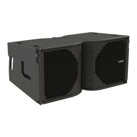
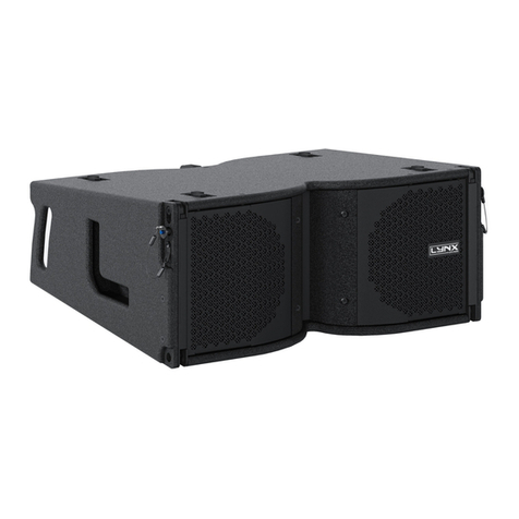
Lynx LX-F6 User manual

Lynx Pro audio S.L.
Valencia, Spain - www.lynxproaudio.com - info@lynxproaudio.com
USER MANUAL
V.13.10
LX-F6
LX-F6P

LX-F6
LYNX Pro Audio S.L. - Valencia, Spain - www.lynxproaudio.com - info@lynxproaudio.com
Class D Powered (bi-amplified)
Integrated Digital Processing
Internal temperature control
Electronic protection
Digital inclinometer system
High quality components
Online monitoring available

This user manual is property of Lynx Pro Audio S.L. Any reproduction of this manual, by any means is strictly prohibited.
Copyright 2013. All rights reserved.
Manufacturer
CB SCHEME, IEC SYSTEM FOR CONFORMITY TESTING AND CERTIFICATION
OF ELECTRICAL EQUIPMENT
CE CERTIFICACTION, EUROPEAN PRODUCT
LX-F6 / LX-F6P line array cabinet
LYNX Pro Audio S.L.
Calle 7 - Pol. Ind. Picassent
E-46220 Picassent (Valencia)

CONTENTS
- SAFETY PRECAUTIONS 5
- CABINET INTRO
SPECIFICATIONS 6
BACK PANEL 7
CONNECTORSANDCONNECTIONS 8
-CONFIGURINGTHECABINETDSPOPTIONS
CONFIGURINGTHECABINETDSPOPTIONS 9
CONFIGURATIONPANEL 9
SELECTTHEINPUT:DIGITAL/ANALOG 12
SELECTANDRUNPRESETS 10
CONFIGURINGTHELINEARRAY 11
NCABINETS 11
AIRABSORTIONCOMPENSATION 13
THROW 13
MANUALANDAUTOMATICMODES 14
ONLINECONTROLSYSTEM 15
CONFIGURINGETHERNET 16
-SOFTWARERAINBOW 22
-ACCESSORIES 24
-LYNXF6FLYINGSYSTEM
INTRO 25
TECHNICALDATA 27
SAFETYPRECAUTIONS 28
HOW TOUSE THEFLYING FRAME 29
ASSEMBLYANDANGULATIONOFTHECABINETS 31
MAINTENANCE 32
INSTALL&RIGGINGACCESSORIES 35
-GUARANTEE 41

LX-F6
Before starting to use thisdevice, please read this instruction manual carefully.
Keep theseinstructionsin theplace where the equipmentwill be used andwitheasyaccessto them.
- Electrical appliance.
Theexclamationmark withina triangle identifiesthepresenceofelectricity.Usethe system carefully
without wet hands or feet. Avoid installing the speaker in wet or excesivelly humid places. Regularly
check thecondition of the cablesand make sure these arenotbeing walked on or pinched. Connect
thespeakertobipolar,earthedmains.Themainsplugmustbeconnectedtotheappropriateprotection
(fuseorbreaker).Connectiontoanyothertypeofmainscouldresultinanelectrical shockandviolate
local electrical codes. DO NOT CONNECT OR DISCONNECT THE AC POWER CONNECTORS
UNDER LOAD.
- Heavy equipment.
Apply back protection when using the system. Avoid loading and unloading at heights.
- Electrical shock risk.
The diagonal mark within a triangle identifiesthe presence of dangerous voltage.
Do not open or handle the interior of the box. These parts are not to be adjusted by the user. For
maintenance and/or repair please go to an authorized service centre.
In order to reduce the risk of electric shock, disconnect from AC before plug in or unplugging Audio
signal cables. Reconnect to AC only if all signal connections are made and secured.
Never manipulate the ground type plug provided.
The AC mains plugs should always remain accessible for operation.
Unplug the loudspeaker during storms or when it’s being used for a long time.
- Hearing damage risk.
These systems can reproduce large quantitiesof sound pressure which can damage hearing. Take
precautions if you are going to be near them for extended amounts of time and do not get too close.
- Hanging – Flying.
Do not hangthe cabinetsfrom the handles or from any otherpartother than the designatedhanging
point. When flying this system please observe the technical and “Lynx On Stage” software data
carefully.Neverexceedthemaximumsafeworkingloadsorignoretheinstructionsincludedwithinthis
manual. Use Only flying accessories provided byLynxPro Audio S.L.
Rigging must be always carried out by professionals.
- Delicate Material.
Pleaseensurenoforeignobjectorwaterentersthespeaker.Donotplacematerialthatcontainsliquid
on or near the unit. Only clean the unit with dry cloths. Do not use solvents.
-Overheating – Fire risk.
Toreducetheriskofthespeakeroverheating,avoiddirectcontactwithsunlight.Avoidplacingtheunit
closeto heatinducing objects such asradiators.Do not cover theequipment in useand do notblock
anyventilationopenings. Donotputnakedflame,suchaslightedcandles,close orontopoftheunit.
- Electromagnetic and interferente emissions.
Avoid placing objects which through electromagnetic waves can damage the unit, such as mobile
phones, lap tops, magnetic strip cards etc.
This system complies with normatives EN55103-1 (1)
EN55103-2 (2)
(1) This device maynot cause harmful interferences.
(2) Thisdevice may receive interference including interferences that may cause undesired working.
-IMPORTANT NOTE.
This Equipment must be used in accordance with these instructions and by trained professional
personnelonly.
This equipment should not be used in places with extreme tropical climates. Don’t expose this
apparatus to extreme humidityand or temperature values.
5
LX-F6
INTRODUCTION
Tofacilitate,correctandreliableuseoftheLynxF6LineArraywehavedesignedthisinstructionmanual.Please
read the manual carefullybefore proceeding to install the system.
When flying this system please observe the technical and “Rainbow” software data carefully. Never exceed
the maximum safe working loads or ignore the instructions included within this manual.
SPECIFICATIONS:
FREQUENCY RANGE 75Hz -20KHz
FREQUENCY RESPONSE 90Hz- 18KHz ± 3dB
HORIZONTAL COVERAGE 100º
VERTICAL COVERAGE According to Array configuration
MAX SPL 124 dB/ 127dB peak 1w@ 1m
TRANSDUCERS LF/MF: 2 x 6" Custom Nomex Cone Neodimium
HF: 1 x 5" Air Motion Transformer with horn
SHAPE Bass Reflex Direct Radiation
SIGNAL CONNECTION NEUTRIK connectors XLR Male Input
XLR Female Loop Thru
AC POWER 230v / 115v selectable. 50/60 Hz 3A
AC CONECTIONS 16A NEUTRIK POWERCON with Looping Output
ONLY LX-F6 ACTIVE CABINET
POWER AMPLIFIER 1500W Class D with Switching Power supply
1000W Low/Mid + 500W High
DSP Internal Lynx processor DSPB-22® with FIR filters
CABINET ADJUSTMENT Back panel LCD screen
INTERNAL CONTROLS Cabinet Angle detection / Temperature sensor /
Fan Speed control
CONTROL CONNECTIONS USB (DSP programming),
ETHERNET* (Online Monitoring System OMS®)
CONSTRUCTION 15 mm Premium Birch plywood
FINISH High resistant water-based black paint
FRONT DESIGN Black steel grille
DIMENSIONS (H x W x D) 204 x 646 x 290 mm
204 x 687 x 290 mm with ball-pins
WEIGHT LX-F6 23 Kg (50 lbs)
WEIGHT LX-F6P 20 Kg (44 lbs)
INTERCABINET ANGLE 0º/ 0,5º/ 1º/ 1,5º/ 2º/ 2,5º/ 3º/ 4º/ 5º/ 6º / 7º
ADJUSTMENT 8º / 9º + 7º Front adjust
RIGGING Integrated flying plates
6

LX-F6
124 3
56
7
1.- SPK LINK IN.
2.- SPK LINK OUT.
2
1
This passive cabinet includes exactly the same components as the active version, but without the amplification.
By linking this passive cabinet as «a slave» to an active one it takes the active features including the corrections
appliedfrom the DSPB22 and the inclinometer and takes the amplification and processing from the activeversion.
Itobtainsthe frequencyresponsecorrectionbyairabsorption,phaseadjustments,amplitude,Crossoverfiltersand
RMSand peak double limitation.
Bylinkingthecabinetsinthisway(1passive+1active),thesystemdeliversexactlythesamepowerasifallcabinets
were active but with the linking option it considerably reduces the weight and the cost of the system.
LX-F6 BACK PANEL
1.- SIGNAL INPUT.
2.- SIGNAL LINK.
3.- AC INPUT.
4.- AC LINK (max. +2 cabinets).
5.- USB.
6.- DSP CONTROL.
7.- SPK LINK OUT.
8.-ETHERNET OPTION
LX-F6P BACK PANEL
8
7

LX-F6
XLR AEREAL CONNECTORS
XLR SOCKET CONNECTORS
CONNECTORS AND CONNECTIONS
OUTPUTS
1.- EARTH
2.- LIVE (+)
3.- LIVE (-)
1
3
2
INPUTS
1.- EARTH
2.- LIVE (+)
3.- LIVE (-)
2
3
1
Connect to output
Connect to input
2 Live(+)
3 Live(-)
1 Earth
3 Live(-)
1 Earth
2 Live(+)
SOCKET POWERCON CONNECTORS
L - Line
N - Neutral
- Earth
8

LX-F6
LX-F6
LX-F6
LX-F6
LX-F6
LX-F6
LX-F6
ACTIVE SYSTEM CONNECTION EXAMPLE (6 CABINETS)
Connect to signal output
Connect to AC output
SOCKET POWERCON CONNECTORS
L - Line
N - Neutral
- Earth
- CAUTION: DO NOT CONNECT OR DISCONNECT THE AC POWER CONNECTORS
UNDER LOAD.
9

LX-F6
LX-F6
LX-F6
LX-F6P
LX-F6P
LX-F6
LX-F6P
Connect to signal output
Connect to AC output
MIXED ACTIVE/PASIVE SYSTEM CONNECTION EXAMPLE (3 ACTIVE + 3 PASSIVE CABINETS)
10

LX-F6
11
CONFIGURING THE CABINET DSP OPTIONS.
From the buttons below the display on the Lynxcabinet’s back panel you are able to configure the Basic
adjustmentfunctionsoftheinternalDSP.
NOTE:You mustapply the desired configurationin each cabinet.Thisis done via the buttons located on the back
panel of thecabinetandrequireselectricalpowertowork.
From the LX cabinet’sback panel you are able toconfigure 4 basic internal DSP adjustments:
-Numberofcabinetsinthearraytoapplyshelvingequalizationfor frequencyresponsecorrection.
-Airabsorptioncompensationatvarious“throw”distances.
-EnableordisabletheInclinometer.
-Enableordisable theautomaticcorrectionfeature.
Note: Finite Impulse Response (FIR) filters are used in the signal processing of the LX-V8 cabinet.FIR is a type of
digital filter withlinear phase characteristics.Thisfrees system designers from the constraintsof phaseanomalies
associatedwith analoguefiltersor their digital versions(IIR,Infinite ImpulseResponse). When properlyused,FIR
filteringcanaudiblyimproveasystem’simpulseresponseandreducecrossoverinterference.
CONFIGURATION PANEL
Onthebackpanelyouwillsee3buttonsandaninformationscreen,onwhichyoucanreadtheestablishedparameters
andinformationsuchasdigitaloranaloginput,amplificationmoduletemperature,inputsignallevelandnameofthe
currentpreset(Fig1).Ifchangesarenotmadethedisplaywillautomaticallydimtosaveenergyandavoidunnecessary
light in situations where light is not wanted. To re-activate the light simply press the OK button.
Fig 1

LX-F6
SELECT THE INPUT: DIGITAL OR ANALOG
There are four input options: Analog / Digital L / Digital R / Digital L+R
To select the input mode just press the OK button (3) and the up button (1), both at the same time but pressing
the OK button first. Then you can select one of the four optionsusing the up button (1). To confirm your selection
press OK(3) until the progressbar finishes. The displaywill show an inverted D (digital) or an inverted A(Analog)
so you can always know if the input is digital or analog.
123
SELECT AND RUN PRESETS
To change the presetconfiguration just pressthe up button (1) and down button(2) until you see thetitle and
preset number required (Fig2).Once found, pressOK (3)until theprogressbar finishes(Fig3). Thedisplaywill
indicate“LoadingDSP”(Fig4)
Fig 3 Fig 4
Note:
In case of a power cut, theDSP willsave its last configuration when restarted.
Fig 2
12

LX-F6
CONFIGURING THE LINE ARRAY.
Note:
Youmustapplythedesiredconfigurationineachcabinet.Thisisdoneviathebuttonslocatedonthebackpanelofthe
cabinet andrequireselectrical power towork.For yourcomfort, we recommend you do thisbefore flying the array.
Onthebackpanelyouwillsee3buttonsandaninformationscreen,onwhichyoucanreadtheestablishedparameters
andinformationsuchasamplificationmoduletemperature,cabinetinclinationandnameofthecurrentpreset.
Ifchangesarenotmadethedisplaywillautomaticallydimtosaveenergyandavoidunnecessarylightinsituationswhere
light isnot wanted. To re-activate the light simply pressthe OK button.
13

LX-F6
TheDSPincorporates5ofthemostcommonconfigurations:
4,6,8,10or12cabinets,maintainingthepresetof12cabinets
forlargersizearrays.Selecttheconfigurationwhichyoubelieve
to be acoustically correct. If you do not wish to carry out any
further adjustments,press OK until the progress bar finishes.
The displaywill indicate“LoadingDSP”.
Note:
In case ofa powercut,the DSP will save itslast configuration when restarted. However, if itwasin AutoMode, itwill
take the data from the inclinometer and re-calculate the compensation algorithms.
14
N CABINETS.
With this button you can select the number of cabinets which will make up your array.
Bydoingthis,theDSPwill applyashelvingfilter in thelowandmidrangeto correctthefrequencyresponseand thus
ensure that the response maintains flat.
It is known that one of the disadvantages of a linearraysystem isthatthe low and midrange of frequenciescannot
be precisely vertically corrected, whereas high frequency drivers have their own waveguide to do this.
For thisreason, you can set up a line array to cover “x” area distance, and you can obtain a directed and controlled
highfrequencyrange.However,itwillnotbethesameonthemidandlowrange,ifyoustayatonepointofthecoverage
area, you will hear oneofthe highfrequencydriversbut you will alsobe ableto listento thewhole lowmid speakers,
obtaining a decompensated frequency response.
You can see this on the measurements comparing 1,4 and 8 cabinets(Black = 1xLX-F6, Red = 4xLX-F6, Green
= 8x LX-F6)

LX-F6
AIR ABSORPTION COMPENSATION
As sound travels over distance, it starts to lose its energy due to atmosphere and physical properties. This varies
according to factors such as relative humidityand temperature and is most appreciable with high frequencies. To
compensate for this lossthe LynxLX cabinets applyspecial equalization algorithms.Thiscompensation iscarried
out for 3 types of throw: Short, Mid and Long.
THROW
After selecting thenumber of cabinets,the second button enables you to change the configuration of the throw as
follows:
- Shortthrow (Black)
-Midthrow(Red)
-Longthrow(Green)
-Manual(withnocorrection)
-Auto(Readstheinclinometerreadinganddependingonthecabinet’sinclinationthismodewillapplytheappropriate
parameter) Note: This data is only taken on DSP Start up to avoid unexpected equalization changes caused by
unnecessarymovementofthearray.Thismeansthatoncethecabinetshavetheirfinalinclination(thearraymustbe
lifted,notstackedonthestage)youhavetorestartthepresetinordertoapplythenecessaryEQfor therealinclination
of each cabinet.Then you can liftthe arraycompletely.
To manual setupfrom theback panel,separatethecoverage area in 3smallerzones,one closeto thearray,one in
the middle and one further awaytrying to ensure theyare similar in size. Depending on the size of the array and its
angulationyoucanaddorremovecabinetstoeachzone.Oncethisisdone,enterthetypeofthrowintoeachcabinet
bearinginmindwhichareatheyaretargeting.
15

LX-F6
With classic configurations, the higher cabinetshave the task of covering the area furthestaway, thusneeding the
“Long Throw” preset. Remember you must enter this preset in to everycabinet that requires thisconfiguration.
Choosetheconfigurationwhichmeetstheneedsofyourinstallation.Ifyoudonotneedtomakeanyfurtherchanges
press OK until the progress bar finishes. The display will indicate “Loading DSP”.
MANUAL MODE
Byselecting Manual mode,the system does nottake in to account thenumber of boxes or the inclination, and uses
thefactoryequalizationparameters,crossoveranddynamics.Thisenablesyoutomanuallycorrectthesystem with
anexternal processorif the configurationisnotcommonor you desireadifferent typeof adjustmentother thanthat
supplied bythe factory.
AUTOMATIC MODE
InthismodethecabinetwillreadtheinclinometerinformationuponStartupandthenapplythecorrespondingpreset
according to the inclination of the cabinet. This onlyhappens when the cabinet is switched on and will last until the
next reading which will be when the power is taken up again. This is done to anticipate movements such as wind
causing variations of the inclination and changing the configuration when not desired.
Averagevalueshavebeentakentodetecttheangulationandapplydifferentthrowpresetsbasedonthemosttypical
configurations:
- If the cabinet has between 0º and –13º The Long Throw preset will be applied.
- If the cabinet has between –13,1º and –21º The Mid Throw preset will be applied.
- If the cabinet has between –21,1º and –90º The Short Throw preset will be applied.
Note: If positive degree values are detected, the DSP Long Throw preset will be applied.
16

LX-F6
17
ONLINE CONTROL SYSTEM
Who is it for?
UsersofSelf poweredDSPincorporated LynxProAudio Cabinetswheretheuserhasrequestedthecabinetsbe
supplied with the Ethernet Module kit.
What is it for?
Obtaindetailedinformationofcabinetbehaviourandmonitorthecabinet/sinrealtime.Youcanchangethe
preset, gain,mute and polarity. You can also activate theair absorptioncompensation and select the «SOLO»
mode.
How does it work?
Via Ethernet (cable or wireless). Once installed, the O.C.S. software automatically detectsall the cabinets
connected to the network and displaysthem in the O.C.S. window on theusers PC.
What does it show?
Aswell as displaying the cabinetmodel and IP addressthe O.C.Swill be monitoring in real time and the user will
beabletoviewRMSlevels,Inputclip,powermoduletemperature,compressionlevels,airabsorption
compensationandcabinetangulation.

LX-F6
CONFIGURING ETHERNET TO WORK WITH THE LYNX F6
There are two possible ways to connect:
1.- Connecting through an ETHERNET SWITCH/HUB::
- You will need a normal CAT5 Cable.
2.- Connecting through a Wirless ETHERNET.
Let us now proceed to configure the Ethernet network, setting the IP address of the computer as static. To do this
go to:
START > CONFIGURATION > NETWORK CONFIGURATION
We will launch the properties of "Local Area
Connection"byclickingtherightmousebutton
and clicking on properties.
18

LX-F6
Select "Internet Protocol (TCP / IP)" and click on
properties.
Select: “Use next IP Address” And write as you wish, in
order to configure your network.
Normally, Ip values will be something like this:
IPAddress:192.168.1.xxx
SubnetMask:255.255.255.0
Where xxxwill be a number between 1 and 254
Accept to quit the network settings and again to apply
them at the nextscreen.Dependingon the WindowsVer-
sion, you will be asked to reboot or not.
Once theComputer isconfigured with a static IPproceed
toconnecttothelinearraysystemthroughtheOCS(online
control system) software.
OpentheOCSsoftwareandfromthe InitialScreenchoose
Ethernetdeviceintotheconfigurationmenu.
It will open a different screen, as follows, there you can see your Network configuration, and the cabinets currently
connected.
19

LX-F6
If you want to change the IP select the cabinet and modifythe assigned IP in order to be able to connect to it.
By default, the Cabinet will have this IP 192.168.1.100
TheNetwork enviromentconsistsinthefirst3setsofthreenumbersseparated bydots.Inordertodetect/communicate
with the cabinets, the software and the cabinets must have the same Network settings.
If it isnot in the same environment WindowsProfesional (2000, XP, VISTA, Windows7and 8) will detect it, but isnot
going tobe able toestablishconnection. InWindowsHome,theprocessor isnotgoing to be detecteduntil thesame
enviromentisapplied.
In order to change the IP settings to havethe same configuration as the PC, we can change the IP addressof the
cabinetsbyclickingintheAssignIPtoselectDevice buttonafter writingintheboxabovethedesired data.Remember
there cannot be twodevices with exactlythe same IPaddress,the last set of three numbers hasto be different and
unique to each one of the devices.
20
This manual suits for next models
1
Table of contents
Other Lynx Speakers System manuals

Lynx
Lynx LX-V12 User manual

Lynx
Lynx CLS-212 User manual

Lynx
Lynx ionic-100 Instruction manual

Lynx
Lynx ADP Series User manual

Lynx
Lynx ADP-215 User manual

Lynx
Lynx GXR-12 User manual

Lynx
Lynx CLS-28 User manual

Lynx
Lynx LX-318C User manual

Lynx
Lynx GXR-LA10A User manual

Lynx
Lynx ionic-100 Instruction manual