10
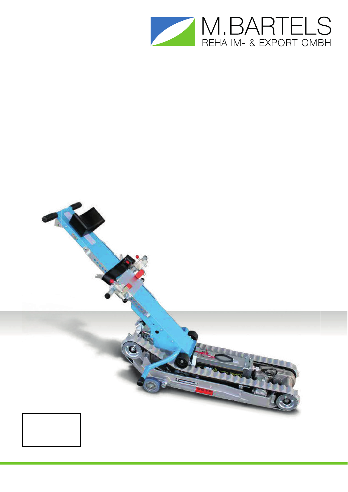
EvacSkate 14
5. DESCRIPTION OF EACH UNIT
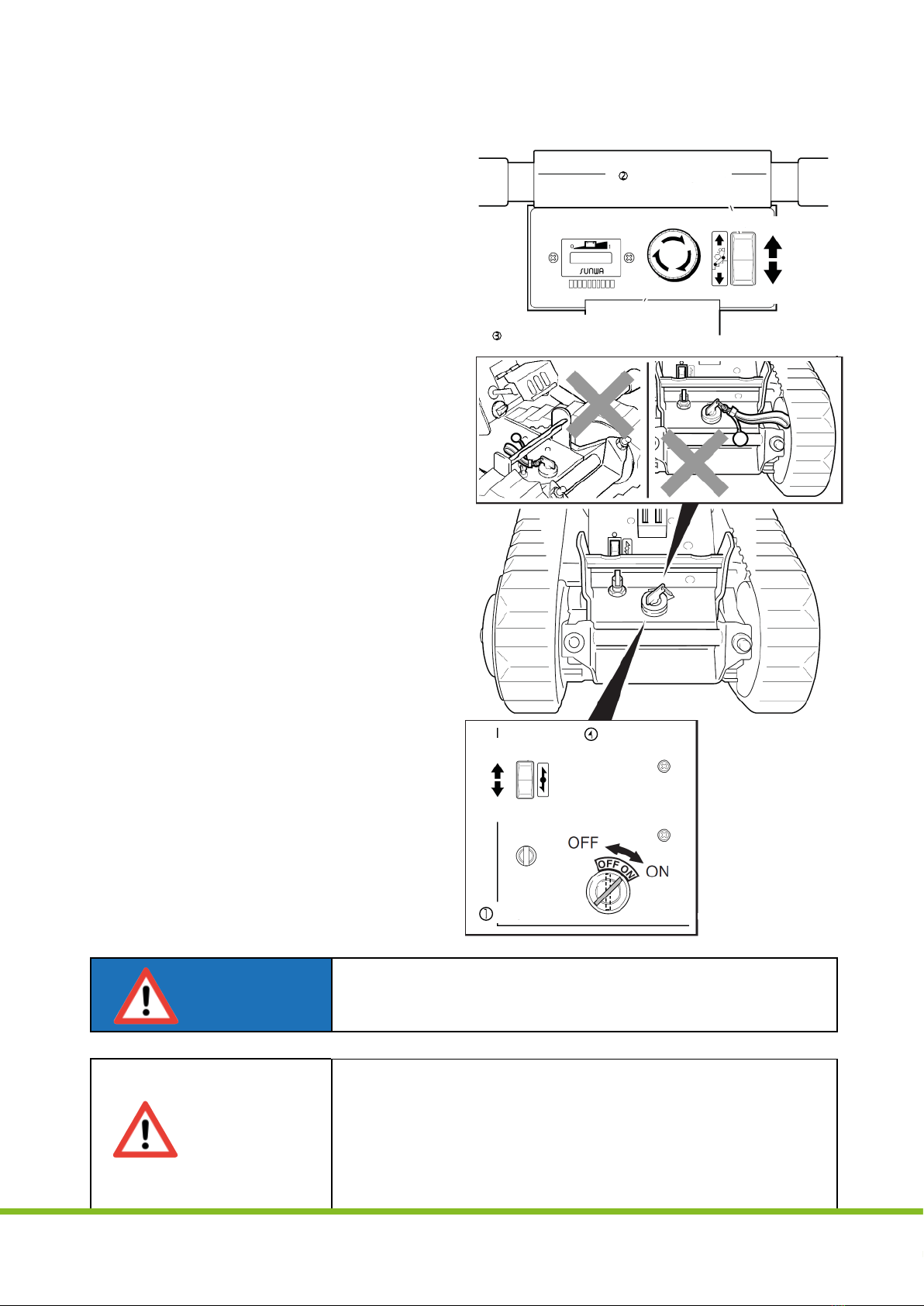
5.1 SWITCHES
1. Key Switch
It turns on/off the power supply. When it is
turned clockwise, the power will be ON and
when turned counter-clockwise, the power
will be off.
NOTE: When STAIRMATE is not to be used
(to be stored, to be charged, to be
transported), turn off Key Switch,
remove Key and keep it in an
appointed place.
2. UP/DOWN Switch
Selects ascent or descent mode. Only while
this Switch is pressed, does the machine
run. If UP Seesaw is pressed, the machine
will ascend. If DOWN Seesaw is pressed,
the machine will descend.When the finger is
released, Switch will automatically return its
neutral position and the machine will stop.
3. Emergency Stop Switch
When this Switch is pressed, the machine
will stop immediately. STAIRMATE won‘t
restart. Even when the other Switch is
pressed.Torelease the emergency stop
condition, turn Emergency Stop Switch in
the „arrow“ indicated direction.
4. Operation Switch on Drive Unit
When Forward or Reverse Switch top
is pressed, the machine will run in the
corresponding direction. When Switch
is released, Switch will return its neutral
position and the machine will stop.
NOTE: This Switch is not to be used for
stair work. Use it only for running
STAIRMATE without Handle Unit.
UP/DOWNSwitch
Ascending
Descending
Emergency Stop Switch
Operation Switch
on Drive Unit
Forward
reverse
Key Switch
Never attach the objects to Key.If any object is attached to Key,
it will be caught in Lock Unit preventing Frame from locking.
This could result in a serious accident
DANGER
• If Key Switch is kept in the ON position, Battery will more
quickly discharge.When the machine is not to be in use, be
sure to turn off Key Switch and remove it.
• Never attach the objects to Key. Doing so may cause the
objects to be caught by Rubber Crawler.
• Pay attention that the operator‘s fingers are not caught in a
Rubber Crawler while the operator pushes Operation Switch
on Drive Uint near floor level.
CAUTION
5. DESCIPTION OF EACH UNIT
10
5. DESCIPTION OF EACH UNIT
10