M-D Pneumatics COMPETITOR PLUS 2002 User manual

LEADING THE SEARCH FOR NEW SOLUTIONS
4840 West KearneyStreet, P. O. Box 2877
Springfield, Missouri USA 65801-2877
Tel 417 865-8715 800 825-6937 Fax417 865-2950
www.mdpneumatics.com
Rotary Positive Blowers
COMPETITOR PLUS rotar
y
blowers are desi
g
ned to be
interchan
g
eable with e
q
uivalent sizes of Roots Universal
RAI®, and man
y
Sutorbilt® California Series B and F, and
Le
g
end™ Series L and P blowers. COMPETITOR PLUS
models are rated up to 15 PSIG dischar
g
e pressure or 16” H
g
dr
y
vacuum.
In addition to interchan
g
eabilit
y
, M-D has improved on
existin
g
desi
g
ns with the followin
g
superior features ordinaril
y
found onl
y
on premium blowers:
Helical Gearing
COMPETITOR PLUS blowers are timed with hardened,
precision helical
g
ears, ke
y
ed to the rotor shafts, not taper fit
spur
g
ears offered b
y
other manufacturers which have
g
reater
backlash, and can slip and lose timin
g
. Helical
g
ears are also
q
uieter, reducin
g
mechanical noise.
Stronger Bearings
COMPETITOR PLUS blowers include double row ball
bearin
g
s at the
g
ear end, stron
g
er than sin
g
le row ball
bearin
g
s offered b
y
other manufacturers. Drive shaft bearin
g
is c
y
lindrical roller t
y
pe for additional stren
g
th a
g
ainst side
loadin
g
from V-belt drives. As a result of this superior desi
g
n,
COMPETITOR PLUS blowers offer an avera
g
e desi
g
n
bearin
g
life of up to 50%
g
reater than models offered b
y
other
manufacturers.
Rotors with Integral Shafts
COMPETITOR PLUS blowers include precision machined
ductile iron rotors with lar
g
e, inte
g
rall
y
cast shafts, not press
fit and/or pinned shafts offered b
y
other manufacturers, which
can loosen over time and cause rotor clash. All rotors are
d
y
namicall
y
balanced for vibration-free rotation.
Positive End Clearances
End clearances are positivel
y
established at the blower
g
ear
end, eliminatin
g
the risk of shiftin
g
end clearances when
installin
g
or removin
g
drive components. This also eliminates
the need for those special fork and saddle tools re
q
uired b
y
other brands to reset end clearances.
Polished Sealing Surfaces
All shaft surfaces in contact with sealin
g
members are
polished to reduce seal wear and risk of leaka
g
e.
Individually Tested
Ever
y
COMPETITOR PLUS blower is factor
y
tested to assure
y
ou of the hi
g
hest
q
ualit
y
. While some manufacturers perform
onl
y
sample testin
g
, M-D
g
oes the distance to insure that
y
our
blower meets our ri
g
id ISO 9001 re
g
istered
q
ualit
y
standards.
ISO 9001 Registration
COMPETITOR PLUS blowers are manufactured under M-D’s
ISO 9001 re
g
istered
q
ualit
y
assurance pro
g
ram, the first
American manufacturer of rotar
y
blowers to
g
ain such
international reco
g
nition.
Warranty
Ever
y
COMPETITOR PLUS blower is backed b
y
M-D’s limited
warrant
y
for a period of 18 months after installation or 2
y
ears
after ori
g
inal blower shipment, whichever occurs first.
Versatility
COMPETITOR PLUS blowers can be field converted from
horizontal to vertical flow, or vice versa, without an
y
special
tools or
additional components.
Metric Availability
All COMPETITOR PLUS blowers are available with metric drive
shaft and process connections.
Worldwide Sales and Service
With sales offices and service facilities located on six continents,
y
ou can be assured of availabilit
y
and service for
y
our
COMPETITOR PLUS blowers.
Material Specifications:
Housin
g
: Cast iron
End Plates: Cast iron
End Cover: Cast iron
Rotors: Ductile iron
Shafts: Ductile iron cast inte
g
rall
y
with rotors
Bearin
g
s: Gear end - Double row ball, both rotors
Drive end - C
y
lindrical roller on drive rotor
Sin
g
le row ball on driven rotor
Drive Shaft: Ductile iron, cast inte
g
rall
y
with drive rotor
Gears: Heat treated allo
y
steel, helical cut
Seals: Lip seals on rotor shafts and drive shaft
Lubrication: Oil splash on
g
ear end,
g
rease on drive end
Model
Size Max.
Press.
PSI
Max.
Vac.
(in. Hg)
Nominal Min.
RPM @ Max.
Disch. Press.
Nominal Max.
RPM @ Max.
Disch. Press.
Displ.
CFR
2002 12 16 2940 5275 .016
2004 7 14 1480 5275 .032
3003 12 15 2080 3600 .0616
3006 7 12 1150 3600 .102
4002 15 16 1820 3600 .061
4005 10 14 1300 3600 .121
4007 7 14 1000 3600 .160
5003 15 16 1900 2850 .132
5006 10 15 980 2850 .221
5009 7 14 700 2850 .323
6005 15 16 1240 2350 .246
6008 12 16 890 2350 .395
6015 6 12 600 2350 .740
Blower SPEED 2 PSIG 4 PSIG 6 PSIG 7 PSIG 10 PSIG 12 PSIG 15 PSIG Max. Vacuum
Model (RPM) CFM BHP CFM BHP CFM BHP CFM BHP CFM BHP CFM BHP CFM BHP “ Hg CFM BHP
2002 1170
3600
5275
7
46
73
0.3
0.8
1.2 41
68 1.3
1.9 38
64 1.8
2.7 36
63 2.1
3.1 32
59 2.8
4.2 29
56 3.3
4.9
6
14
16
3
28
51
0.3
2.1
3.4
2004 1170
3600
5275
19
97
150
0.4
1.3
1.9
12
89
143
0.8
2.3
3.4 83
137 3.3
4.9 81
134 3.8
5.6
6
14
14
13
69
122
0.6
3.8
5.5
3003 1170
2700
3600
49
143
198
0.8
1.9
2.5
39
133
188
1.4
3.3
4.5
31
126
181
2.1
4.8
6.4
28
122
178
2.4
5.5
7.4 114
169 7.7
10 109
164 9.1
12
10
14
15
27
107
158
1.7
5.4
7.7
3006 1170
2700
3600
86
242
334
1.2
2.8
3.8
72
228
320
2.3
5.2
7.0
62
218
310
3.3
7.6
10
57
213
305
3.8
8.9
12
10
12
14
56
202
283
2.7
7.5
12
4002 880
1760
3600
34
87
198
0.6
1.3
2.6
26
79
190
1.1
2.2
4.5
19
73
184
1.6
3.1
6.4
17
70
181
1.8
3.6
7.4 63
174 5.0
10 59
170 5.9
12 164 15
10
14
16
16
57
159
1.3
3.5
8.2
4005 880
1760
3600
70
177
399
1.1
2.2
4.5
55
162
384
2.0
4.1
8.3
44
150
373
3.0
5.9
12
39
145
368
3.4
6.9
14 132
355 9.6
20
8
13
14
47
127
349
2.0
63
13
4007 880
1760
3600
93
234
527
1.4
2.8
5.7
74
214
508
2.6
5.3
11
59
199
493
3.9
7.7
16
52
193
486
4.5
8.9
18
8
12
14
63
176
472
2.6
7.6
18
5003 710
1760
2850
64
203
346
1.0
2.6
4.1
52
191
334
1.6
4.6
7.4
43
181
325
2.7
6.6
11
39
177
321
3.1
7.6
12 167
310 11
17 160
304 13
21 152
295 16
25
10
14
16
37
158
289
2.2
7.5
14
5006 710
1760
2850
108
340
581
1.6
3.9
6.4
87
319
560
3.0
7.3
12
71
303
544
4.3
11
17
65
297
537
5.0
12
20 278
519 17
28
10
14
15
62
263
496
3.6
12
21
5009 710
1760
2850
173
513
865
2.2
5.5
8.9
151
490
842
4.2
10
17
133
472
824
6.2
15
25
125
464
816
7.2
18
29
10
12
14
122
445
779
5.1
15
28
6005 710
1760
2350
129
387
532
1.8
4.5
6.0
110
368
513
3.3
8.3
11
95
354
499
4.9
12
16
89
347
492
5.6
14
19
72
330
476
7.9
20
26 160
304 23
31 307
452 29
38
12
16
16
73
300
445
4.8
16
21
6008 710
1760
2350
207
621
854
2.7
6.8
9.1
176
591
824
5.2
13
17
153
568
801
7.6
19
25
143
557
790
8.9
22
29
116
530
764
13
31
41 515
748 37
50
12
16
16
117
481
714
7.5
25
33
6015 710
1760
2350
387
1164
1601
4.9
12
16
330
1107
1544
9.5
23
31
286
1063
1500
14
35
46
8
12
12
300
996
1433
9.3
34
46
Performance
Pressure performance is based on inlet conditions
of 14.70 PSIA and 70oF.
Vacuum performance is based on inlet temperature
of 70oF and discharge pressure of 14.70 PSIA.
In conjunction with our program of continuous
testing and upgrading, all specifications are subject
to change without notice.
All data are approximate. Request a quotation for
your specific application.
Your Local M-D Sales Professional is:
LEADING THE SEARCH FOR NEW SOLUTIONS
4840 West KearneyStreet, P. O. Box 2877
Springfield, Missouri USA 65801-2877
Tel 417 865-8715 800 825-6937 Fax417 865-2950
www.mdpneumatics.com
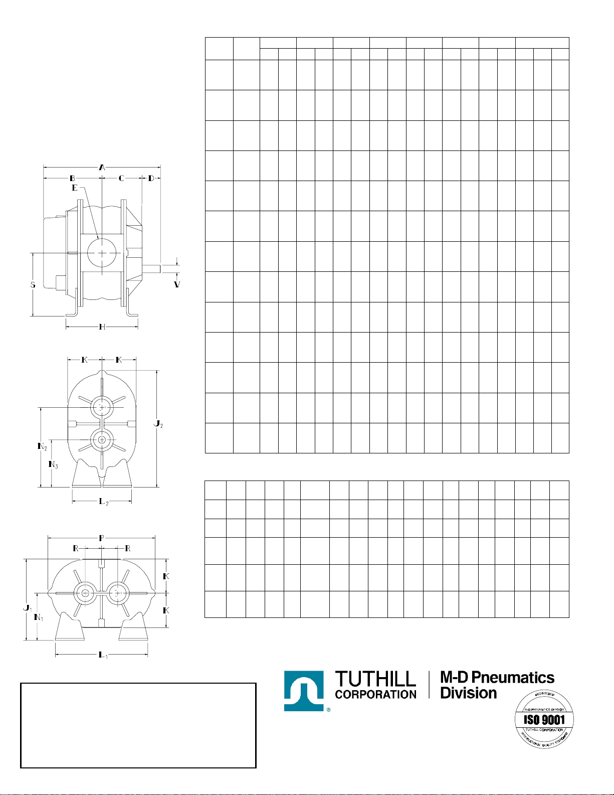
Model
Size A B C D E H J1 J2 K L1 L2 N1 N2 N3 P R S V
2002
2004 9.75
11.75 4.63
5.63 2.63
3.63 2.50 1” NPT
2” NPT 5.00
7.00 6.88 9.69 3.13 5.13 5.13 3.75 6.25 3.75 9.38 1.25 5.00 .625
3003
3006 12.19
14.56 5.94
7.13 3.75
4.94 2.50 2” NPT
2½” NPT 7.63
10.00 8.94 12.81 3.94 7.25 7.25 5.00 8.50 3.75 12.19 1.75 6.75 .750
4002
4005
4007
12.56
15.31
17.06
5.88
7.25
8.13
3.69
5.06
5.94 3.00 1½” NPT
2½” NPT
3” NPT
7.25
10.00
11.75 10.63 15.13 4.38 8.00 8.00 6.25 10.25 5.00 13.69 2.00 8.25 .875
5003
5006
5009
14.88
17.50
20.50
7.00
8.31
9.81
4.50
5.81
7.31 3.38 2½” NPT
4” NPT
4” NPT
8.38
11.00
14.00 12.13 17.38 5.38 10.50 10.50 6.75 11.25 6.25 17.19 2.50 8.75 1.125
6005
6008
6015
18.38
21.38
28.38
9.06
10.56
14.06
5.63
7.13
10.63 3.69 3” NPT
5” NPT
6” FLG
10.13
13.13
20.18 15.06 21.69 6.25 17.00 11.00 8.75 14.75 8.75 19.81 3.00 11.75 1.375
Dimensions
Values shown are approximate and should not be used for construction.
Certified drawin
g
s are available throu
g
h
y
our local M-D Sales Professional.
0899

Tuthill Pneumatics
Rotary Positive Displacement
Air Blower
2002 3003 4002 5003 6005
2004 3006 4005 5006 6008
4007 5009 6015
Models
INSTALLATION
OPERATION
MAINTENANCE
REPAIR
01/2001
WARNING
DO NOT OPERATE BEFORE
READING MANUAL.
LEADING THE SEARCH FOR NEW SOLUTIONS
4840 West Kearney Street, P. O. Box 2877
Springfield, Missouri USA 65801-2877
Tel 417 865-8715 800 825-6937 Fax 417 865-2950
E-mail: [email protected]
www.mdpneumatics.com

!WARNING
!WARNING
SAFETY INSTRUCTIONS
1. Do not operate before reading
the enclosed instruction manual.
2. Use adequate protection,
warning and safety equipment
necessary to protect against
hazards involved in installation
and operation of this equipment.
Do not operate
without guards
in place
Do not touch
hot surfaces
SAFETY WARNING
• Keep hands and clothing away from rotating machinery, inlet and discharge openings.
• Blower and drive mounting bolts must be secured.
• Drive belts and coupling guards must be in place.
• Noise level may require ear protection.
• Blower heat can cause burns if touched.
TUTHILL PNEUMATICS GROUP Springfield, MO USA
NOTICE
The above safety instruction tags were attached to your unit prior
to shipment. Do not remove, paint over or obscure in any manner.
Failure to heed these warnings could result in serious bodily injury
to the personnel operating and maintaining this equipment.
!WARNING
Keep body and
clothing away from
machine openings
Hearing
Protection
Required
!CAUTION
2

TABLE OF CONTENTS
SECTION PAGE
INTRODUCTION 4
OPERATING DATA 4
INSTALLATION 5
LUBRICATION 6
PREVENTATIVE MAINTENANCE 7
STARTUP CHECKLIST 7
TROUBLESHOOTING 8
RECOMMENDED SHUTDOWN PROCEDURE 9
DISASSEMBLY AND INSPECTION 10
BLOWER DISASSEMBLY 10
BLOWER ASSEMBLY 12
MAINTENANCE AND SERVICE SPECIFICATIONS SHEET 14
SPECIAL TOOL DRAWINGS 15
CUTAWAY VIEW AND PARTS LIST 16
WARRANTY STATEMENT 17
SAFETY PRECAUTIONS
For equipment covered specifically or indirectly in this instruction book, it is important that all personnel observe
safety precautions to minimize the chances of injury. Among many considerations, the following should particularly be
noted:
• Blower casing and associated piping or accessories may become hot enough to cause major skin burns on
contact.
• Internal and external rotating parts of the blower and driving equipment can produce serious physical injuries.
Do not reach into any opening in the blower while it is operating, or while subject to accidental starting. Cover
external moving parts with adequate guards.
• Disconnect power before doing any work, and avoid bypassing or rendering inoperative any safety or protective
devices.
• If blower is operated with piping disconnected, place a strong, coarse screen over the inlet and avoid standing
in discharge air stream.
• Avoid extended exposure in close proximity to machinery with high intensity noise levels.
• Use proper care and good procedures in handling, lifting, installing, operating, and maintaining the equipment.
• Other potential hazards to safety may also be associated with operation of this equipment. All personnel
working in or passing through the area should be warned by signs and trained to exercise adequate general
safety precautions.
• Hearing protection may be required depending on silencing capabilities.
CAUTION!
Most COMPETITOR PLUS™blowers are
shipped from the factory in a left hand drive,
vertical flow configuration.
If drive shaft location is changed, the oil level
plug and breather must be relocated to proper
positions, as shown to the right.
Failure to change plug location will result in
blower failure and void the product warranty.
This manual suits for next models
12
Table of contents


