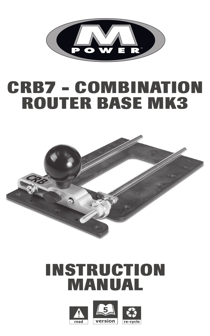
CRB7 PARALLEL SIDE FENCE
Thank you for purchasing MPOWER’s Parallel Side Fence which
should give lasting performance if used in accordance with these
instructions.
The following symbols are used throughout these instructions
denoting risk of personal injury, loss of life or damage to the tool
in case of non-observance of the instructions.
Refer to the instruction manual of your power tool.
INTENDED USE
The Parallel Side Fence has been designed for use with
MPOWER’s Combination Router Base (CRB7), a router, and a
suitable router cutter when performing edge parallel rebates and
edge moldings.
This accessory combined with the fine adjustment of the CRB7
will improve control and offer greater edge to rebate range whilst
achieving an excellent finish.
This accessory can be used as a replacement for the much larger
and more complicated traditional fences supplied with many
makes and models of router.
SAFETY
Please read and understand the safety points at the end of this
instruction as well as the power tool instructions before use.
Please keep these instructions in a safe place. Users must be
competent in safe routing practices before using this product.
ITEMS REQUIRED
• CRB7 Router Base • Router with suitable collet fitted.
• Flat head screwdriver • 5/16” (8mm) drill bit.
• 1/2” (12mm) drill bit. • Hand tools.
• Suitable router cutter
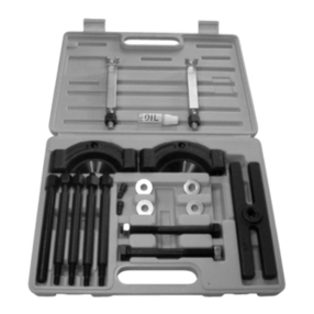
ITEMS ENCLOSED – (See Fig 1)
1) 1x Machined solid Parallel Side Fence (SKU 40051)
2) Internal Pack 10/20 (SKU 40075)
2x 25/64” (10mm) CS machine fixing screws.
2x 3/4” (20mm) CS machine screws,
The Side Fence fixing position is determined by the desired
distance of the routing pass from the edge of the workpiece (See
Fig 3)
Note: Dimensions may vary according to the size and shape of
the router base being used.
*distance between the cutter centre and the edge of the
workpiece.
ASSEMBLY
FITTING THE SIDE FENCE – (See fig 4)
After deciding on the Fence fixing position slide the router off the
CRB7 rods.
Place the fence under the base plate so that the 2x brass
threaded inserts of the fence line up under the chosen
countersunk holes in the top surface of the base plate.
Fit the 2 x 25/64” (10mm) CS machine screws.
Do not over tighten.
Slide the router back onto the CRB7 rods and position it in the
approximate area of the desired router pass.
Fine adjustment of the cutter position can then be carried out
using the Micro Adjuster on the CRB7 (please see the CRB7
instruction manual for further details on this process)
WARNING: When edge moulding only a section of the router
cutter may be revealed to the workpiece edge, meaning the back
side of the cutter will cut into the face of the fence. Rather than
permanently damaging the fence; fit an additional sacrificial
fence.
FITTING A SACRIFICIAL FENCE TO THE SIDE FENCE
We recommend making the sacrificial fence from solid hardwood,
however ply or MDF will work.
Cut and machine the sacrificial fence to 12 x 1.3/8 x 7/8” (300 x
35 x 20mm), (Dimensions can vary according to the users needs
or preference).
Ensure the sacrificial fence is machined flat then lightly sand the
edges to remove any splinters.
Accurately mark out the drilling locations for the 2x fixing holes
by:
Measuring and marking a parallel line 9/32” (7mm) in from the top
edge of the sacrificial fence.
Measure and mark the centre point of the sacrificial fence mid
way down the parallel line. Then place it under the baseplate end
drillings. So that the parallel line can be seen through the
drillings. Using a sharp pencil draw through the drillings, marking
the position of the fixing holes (see Fig 5)
Counter bore the outer/top surface of the 2x fixing holes depth
11/16” (17.5mm) use a 3/8” (10mm) drill bit.
IMPORTANT: The counter bore depth must allow the 3/4”
(20mm) CS machine screws to locate fully* into the machine
inserts of the Fence.
*Fully located = 13/64” (5mm) of the CS Machine Screw thread.
(See fig 6)
Note: The counter bores allow the fixing screw heads to sit well
below the sacrificial fence surface when fitted to the fence.
Attach the Sacrificial Fence to the CRB7 Fence using the 2x 3/4”
(20mm) screws. (See fig 7)
The CRB7 Sacrificial Fence is now fitted and ready to be used.
SPARE PARTS
Fence Assembly 40051
Internal Pack 10/20 40075
MAINTENANCE
Continual satisfactory operation depends upon proper tool care
and regular cleaning.
Cleaning: Regularly clean accessory with a soft cloth.
Lubrication: Your accessory requires no additional lubrication.
ENVIRONMENTAL PROTECTION
Re-cycle raw materials instead of disposing as waste.
Packing should be sorted for environmental-friendly recycling.
The product and its accessories at the end of its life should be
sorted for environmental-friendly recycling.
GUARANTEE
All MPOWER products are guaranteed against any defect in
either workmanship or material, except products that have been
damaged due to improper use or maintenance.
A
Cutter Centre
Workpiece Edge
5/8” (16mm)
3. 7/8” (98mm)
4. 9/32”
(109mm)
7. 1/2”
(190mm)
A CB
SIDE FENCE FIXING POSITIONS
The Side Fence can be mounted in different locations on the
underside of the CRB7 Base Plate (See Fig 2).
1
Sight Line
Sticker
2
9/32”
7(mm)
FIG 5
FIG 4
FIG 3
FIG 1
FIG 2
Through drill the 2x fixing holes using a 3/16” (5mm) drill bit.
FIG 6
FIG 7
Fence
13/64”
Sacrificial
Fence
11/16”
3/16” 3/8”
9/32”
© MPOWER Tools Ltd. 2018
Our policy of continuous improvement means that specifications
may change without notice. MPOWER Tools Limited cannot be
held liable for any material rendered unusable, or for any
form of consequential loss.
