M-Power CRB7 User manual

CRB7- COMBINATION
ROUTER BASE MK
3
INSTRUCTION MANUAL
Please read these instructions before use.
v.IX
COMBINATION ROUTER BASE
(CRB7)
Thank you for purchasing the MPOWER
Combination Router Base (CRB7) we hope you
enjoy using it.
The CRB7 should give lasting performance if
used in accordance with these instructions.
The following symbols are used throughout
these instructions.
Denotes risk of personal injury, loss
of life or damage to the tool in case
of non-observance of the
instructions.
Refer to the instruction manual
provided with your power tool.
SAFETY
Please read and understand the safety points at
the end of these instructions as well as the
power tool instructions before use.
Users must be competent in safe routing
practices before using this product.
PLEASE KEEP THESE INSTRUCTIONS IN A
SAFE PLACE.
INTENDED USE
This accessory is a retro fit, quick change,
multi-functional router base for use with routers
that:
5/16” (7mm) rods.
Min. height 15/64” (6mm)
Max. height 1.19/64” (33mm)
between:
Min. centres 1.11/32” (34mm)
Max. centres 6.7/8” (174 mm).
The CRB7 Combination Router Base is
intended to:
overall versatility of the router.
ove the quality of finish of every routing
pass.
Reduce the possibility of error.
ty during routing.
vel of precision achieved.
ave set up time between tasks.
ave space on storing hand made jigs.
FEATURES
Trenching with a
Clamp Guide.
(50mm) to 5/16” (125mm).
False Panel Groove Copier.
Router Compass
*Radius 3/4” (19mm) - 8.13/16”(224mm).
Router Compass
*Radius 7” (180mm) - 25” (635mm).
*Measured from outside edge of hole and
using a 1/4” (6mm) cutter.
Note: All dimensions shown are based on a T5
router being used with a 1/4” (6.3mm) router
cutter.
ITEMS REQUIRED
Router with a suitable rod size and
centres.
Router cutter.
r.
Tools.
CONTENTS
Page No.
3. Items enclosed & Description of parts
4. Setting Up
Fitting the CRB to your router
Guide rod selection
Loosen the lock nuts
5. Safe cutter alignment
Guide rod adjustment
Crank plate adjustment
6. Fitting the router
Setting the fixed rod
7. Fitting the index rule
Lock Bars
The micro adjuster
8. Operation
Adjustable dadoing with clamp guide
Adjustable offset mortising
Material width 2 - 4.7/8”
9. Material width 4.7/8 - 8.5/8”
Anti-tilt support
10. Adjustable false panel groove copier
Offset baseplate
11. Cutting small circles
Pivot pin storage
Min. Radius 3/4” (19mm)
Max. Radius 4.15/16” (125mm)
Max. Radius 8.13/16” (224mm)
12. Cutting large circles
13.CRB7 Accessories
Maintenance
Environmental protection
Guarantee
14.Safety points
15.Other MPOWER products
2

G
C
E
1
5
4
D
F
1B
E
G
F
6E
3
4B
5B
5C
5D
5E
H
6
6C
6B
6D
6E
6F
1B
1C
2
2B
16 43271234567
123 123
cm
Inches
5
11
1 Bridge: Attaches guide rods to baseplate.
1B Bridge Spacer Shim:
1C Bridge Slot: Provides lateral adjustment.
2 Baseplate: 5mm acrylic router platform.
2B Baseplate Letterbox: Router cutter zone.
3 Bridge Pinchbolt: Secures offset handle
and anti-tilt leg to bridge.
4 Micro Adjuster: Micro adjusts router position.
4B Micro Adjuster Lock Nut: Locks adjustment
securely in position.
5 Adjuster Guide Rod 8mm: Attaches to
router. Micro adjustable.
5B Adjuster Guide Rod M5 Locknut: Attaches
the adjuster guide rod to the adjuster guide
rod crank plate.
5C Adjuster Guide Rod M5 Washer x 2
5D Adjuster Rod: Attaches adjuster guide rod to
bridge via micro adjuster.
5E Adjuster Rod Crank Plate: Fixes adjuster
rod to adjuster guide rod.
6 Fixed Guide Rod 8mm: Attaches to router.
6B Fixed Guide Rod M5 Locknut: Attaches fixed
guide rod to fixed guide rod crank plate.
6C Fixed Guide Rod M5 Washers x 2:
6D Fixed Rod: Fixes to bridge. Adjustment
3
ITEMS ENCLOSED & DESCRIPTION OF PARTS
accommodates various router rod spacings.
6E Fixed Rod M8 Locknut x 2: Locks fixed
rod in position.
6F Fixed Rod Crank Plate: Attaches fixed rod
to fixed guide rod.
7 Offset Handle: Fits into bridge when in
offset baseplate mode.
8 Anti-tilt Leg: Fits into bridge stabilizing the
unsupported side of the router.
9. Pivot Pin: Attach to underside of base.
Forms the axis point when routing arcs and
circles.
10 Mortise Pillars: Attach to underside of
base. Guides CRB7 when mortising.
11 Indexed Rule: Self adhesive.
12 No.6 x 1/2” Csk Woodscrews x 6:
Secures copy tongue batten to baseplate.
13 M4 x 10mm Csk Screws x 3: Fixes pivot
pin and mortise pillars to baseplate.
14 7mm Guide Rods: Enables CRB7 to fit
routers with smaller rod drillings.
15 Compass Pivot Hub: Screws to workpiece.
Attaches to 10mm compass rods.
16 10mm Compass Rods x2: Attaches CRB7
to pivot hub.
17 Woodscrews x3: Fixes pivot hub to
workpiece.
18 Lock Bars: Use to tighten and loosen rods.
(not to scale)
10
13
7x2
8
13
9
12
15
Accessories
16
17 18
14
FITTING THE CRB7 TO YOUR ROUTER
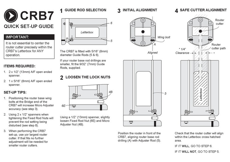
1. Guide Rod selection
5
6
6E
4B
3. Initial alignment
Aligned
5
Router base
wing bolt
A
SETTING UP
Letterbox
The CRB7 is fitted with 5/16” (8mm) diameter
guide rods (5 & 6).
the 9/32” (7mm) guide rods, supplied.
2. Loosen the Lock Nuts
Using 1 x 1/2” (13mm) spanner, slightly loosen
fixed rod nut (6E) and micro adjuster nut (4B). Position the router in front of the CRB7.
Align the router base rod drilling (A) with
Adjuster Rod (5).
Tip: Positioning the router base Wing Bolts
towards the bridge end of the CRB7 will
increase micro adjuster accuracy.
4
IMPORTANT
IT IS NOT ESSENTIAL TO CENTRE THE
ROUTER CUTTER PRECISELY WITHIN
THE CRB7’S LETTERBOX FOR ANY
OPERATION.

5. Guide Rod adjustment
the letterbox cross hatch area.
4. Safe cutter alignment
Router
cutter
Letterbox
Router cutter path
* 1/4”
Clearance *
X
X5
5E2
6E2
5B
5
5E1
5E2
Check that the router cutter will safely align
within the letterbox cross hatch area.
IF IT WILL, GO TO STEP 7.
IF IT WILL NOT, GO THROUGH STEPS 5-6.
Loosen M5 lock nut (5B) using a 5/16” spanner.
Remove adjuster rod (5) from its current crank
plate drilling (5E1) and reposition in the other
drilling (5E2).
Tighten M5 lock nut (5B).
Important: Ensure M5 lock nut is securely
fastened.
For further adjustment fit the rods in the other
crank plate drillings (5E2 & 6E2).
Flip cranked adjuster rod (5) to its outer
position.
6. Crank Plate adjustment
5
7. Fitting the router 8. Setting the Fixed Rod
Aligned
6
Bridge
B
A
6E
B
Hold Still
Align fixed rod (6) with router base rod drilling
(B), so that both rods are aligned.
Slide the router onto both rods until it stops at
the Bridge end of the CRB7 assembly.
Using 2 x 1/2” (13mm) open ended spanners,
tighten both fixed rod nuts.
Tip: Using two spanners when tightening the
fixed rod nuts will prevent the rod setting being
disturbed.
Both guide rod positions are now set.
Important - Before attempting any
machining pass: Ensure that the router is
securely fitted to the CRB7 by checking ALL
CRB7 fixings, including router base wing bolts
and micro adjuster lock nut.
IMPORTANT
Follow the below steps in order:
1. Tighten router base wing bolt (A).
2. Finger-tighten fixed rod nut (6E).
3. Tighten router base wing bolt (B).
6

With the router fitted to the CRB7:
Position the indexed rule (11) to run alongside
the edge of the router base on the fixed guide
rod (6) side. The reading can then be taken
from the index line (11A) against the indexed
rule (11).
When happy with its location:
and debris.
LOCK BARS
Use the supplied lock bars
(18) to help tighten and
loosed the guide rods.
the guide rod drilling to
add leverage.
FITTING THE INDEX RULE
16 4327 1234567
123 123
cm
Inches
5
11
11A
16 4327 1234567
123 123
cm
Inches
5
11 6
11A2
4
THE MICRO ADJUSTER
The CRB7 is fitted with a micro adjuster (4). The
micro adjuster is designed to provide greater
accuracy when positioning the router cutter
prior to use.
Tip: Positioning the router base Wing Bolts
towards the bridge end of the CRB7 will increase
micro adjuster accuracy.
Using the micro adjuster (4) to accurately
position the router cutter.
the surface of the workpiece and lock the
router cutter height in that position.
fixed guide rod (6) and keep the router
fence rod knob locked on the adjuster guide
rod (5).
outer edge of the router cutter precisely with
the desired marking.
Positioning the router cutter using the
index markings on the CRB7.
The micro adjuster (4)
has an indexed line
(4A) machined across
its width (in red),
similarly a
corresponding index
line (1A) is located on
the bridge either side
of the micro adjuster
(4).
Note: When the micro adjuster (4) is rotated
(1.25mm) from its original position. Four
complete rotations will move the router 3/16”
(5mm) etc.
It’s essential to remove the play from
the thread when using the index lines.
the micro adjuster (4) in the desired direction
so that both index lines (1A & 4A) line up.
Retighten the router base wing bolt on the
adjuster guide rod (5).
The router cutter can now be moved a measured
distance accurately using the micro adjuster (4).
Should the router cutter need to be adjusted in
the opposite direction repeat the above step to
remove the play.
Tip: To remove float
or backlash between
the adjuster rod (5D)
and micro adjuster
(4), simply tighten
the micro adjuster
locknut (4B) against
the bridge (1).
4B45D
1
Many routers are manufactured with a cast
indexing line or marking positioned centrally on
the side of the router base (11A).
wish to utilize the indexed rule (11) simply
draw a line on the base using an indelible fine
black marker.
A self adhesive indexed rule (11) is included
with the CRB7.
When fitted to the CRB7 baseplate (2) it will
allow the user to see and reposition the router
to a measured distance relative to its original
position.
7
4A
41A
18
mortised with a mortise pillar (10) on either
side of the work piece. Rotate the CRB7
clockwise until both mortise pillars (10) are in
contact with and tightened against the sides
of the work piece.
(K) sits between the mortise pillars (10) and
roughly lines up with the mortise markings, if
happy fix the router in position by locking the
router base wing bolts on both the fixed and
adjuster guide rods (5 & 6).
If the router requires final adjustment
plunge and lock the router so that the
cutter tip is just in contact with the work
Using a clamp guide and router to rebate across
the width of a work piece is a useful and
common practice. However considerable time is
taken to accurately set the clamp guide at right
angles to the edge of the board simultaneously
ensuring a precise distance from the desired
position of the rebate. The CRB7’s micro
adjuster (4) removes the need to set the
distance between clamp guide and rebate.
Ensure the clamp guide (J) is set at right angles
to the board edge and within the range of the
routers movement on the CRB7’s guide rods
(5&6). Slide the router to the approximate
position of the required rebate and using the
the router onto the CRB7’s adjuster guide rod
(5). Plunge the cutter to the work piece surface
(with the router turned off) and using the micro
adjuster (4) bring the edge of the cutter up to
the line denoting the location of the rebate. Run
the bridge (1) end of the CRB7’s baseplate (2)
up against the clamp guide (J) and using an
even pressure ensure the router moves
smoothly down the length of the clamp guide.
If a deep rebate or groove is needed
several lighter cutting passes may be
required.
(110mm) centre to centre of each other, (using
a 1/4” cutter) they can be routed without
moving the clamp guide, simply slide the router
down the CRB7’s guide rods (5 & 6) to the next
location.
Before use ensure router base wing
bolts are tightened onto the CRB7 guide
rods.
Always isolate router from power
supply before adjustments or during
set ups.
Adjustable Offset Mortising
The CRB7 fitted with mortise pillars (10) saves
time and gives a clean finish.
Material widths between:
2” (50mm) - 4, 7/8” (125mm)
OPERATION
Adjustable Dadoing with a Clamp
Guide
Workpiece
I
5
J
2
J
6
45
2
Workpiece
10
2
FF
13 13
10
C
H
2
D
F
F
Workpiece
10
10
6
5
K
4
C
l
o
c
k
w
i
s
e
F
F
of the baseplate (2) in locations (F) using
the two M4 screws (13) provided.
onto the work piece.
router onto the CRB7.
8

pinchbolt hole from the underside of the
baseplate (2).
against the underside of the baseplate (2).
(5 & 6) and lock the router in position using
the router cutter (K) to sit safely within the
baseplate letterbox.
Max. support height = 3 1/8” (80mm)
Min. support height = 5/16” (8mm)
the router on the work piece (M) as if to
start a routing pass.
anti-tilt leg (8) drops down and the foot
rests on the bench top.
retighten the bridge pinchbolt (3) locking the
anti-tilt leg (8) at the height which will then
support the previously unsupported side of
the router.
Before completing the routing pass
check that the bench surrounding the
work piece is smooth and even. Complete a
couple of dry runs with the router around
the work piece ensuring that the anti-tilt
leg (8) has a clear path and the router
remains stable whilst the pass is
completed.
Anti-Tilt Support
The CRB7’s anti-tilt leg (8) is designed
specifically to aid stability when routing narrow
sections of material. The leg is in two parts so
its height can be reduced if required.
piece surface and use the micro adjuster
(4) to accurately set the cutter position.
It’s important to ensure that the
mortise pillars (10) remain in contact
with the work piece sides along the
complete length of the mortise. If the
position of the mortise is at the very end of
the work piece then additional guide
battens (L) will need to be fitted to prevent
the mortise pillars (10) literally falling off
the end of the work piece.
L
L
K
10
10
Workpiece
4
C
l
o
c
k
w
i
s
e
8
1
3M
K
I
Clamp one guide batten (L) on each side of the
work piece, over lapping the ends. This will give
a wider and longer platform to support the
router.
Depending on the depth of mortise and
material being used, several cutting passes
may be required in order to achieve the
correct depth safely.
movement tightening the mortise pillars (10)
against the sides of the work piece.
piece and feed the machine forwards again
ensuring that the mortise pillars (10) are in
contact with each side of the workpiece.
and release plunge.
until the required mortise depth is achieved.
Material widths between:
4 7/8” (125mm) - 8 5/8” (219mm)
Fit the mortise pillars to locations C - D or C - H
Then follow the same instructions as above.
9
C
H
D
’s guide rods
(5&6).
from the CRB7 bridge (1) allowing the router
cutter to sit safely within the baseplate
‘letterbox’.
hole and lock in position using the bridge
pinchbolt (3).
The CRB7 is now set up and ready for routing.
The handle/bridge (1) end of the CRB7
should be over the work piece.
TIP: To avoid splitting the small section
copy batten (N) screw it in position by
hand not with a drill driver.
r.
py batten (N) slides into the
first groove and moves smoothly along its
length.
cutter and copy batten (N) by sliding the router
use the micro adjuster (4) to finely adjust it’s
position.
base wing bolt on each side of the router base.
Adjustable False Panel Groove
Copier
To repeat a routing pass a set distance from
another pass or to produce a series of closely
routed groves or rebates; use the false panel copy
tongue feature. The CRB7 can be set up easily for
this purpose.
The second groove can now be routed.
Note:racy use a
consistent pressure when holding the router in
position during each pass of the router.
Clean the 2nd groove and slot the copy batten
(N) into it to produce the 3rd groove. Repeat as
required.
Offset Baseplate
The offset baseplate function is designed to
increase the router-base surface contact area to
the work piece improving stability and reducing the
chance of making an error during a routing pass.
12
N
2
5
4
1
Workpiece
K
Workpiece
C
E
E
7
3
I
5
2
1
Workpiece K
py batten (N)
min. 6 5/16” (160mm) length in timber or a
solid plastic i.e. nylon or polyethylene.
Note: The copy batten should copy the size and
profile of the router cutter (K) that will produce
the groove.
Test the finished copy batten in a sample groove
to ensure a snug but not over-tight fit is
achieved.
the first groove on the workpiece. Then:
o.6 woodscrews (12) line up the
copy batten (N) with the three countersunk
baselplate holes (locations C & E) and screw the
copy batten (N) to the underside of the
baseplate (2).
10

The pivot pin (9) can be stored in the back of
the bridge (1) when not in use. The M4 screw
(13) must be screwed into the pivot pin (9) for
the magnetic storage to be effective.
countersunk hole in the baseplate (2) so
that the pivot pin (9) protrudes downwards
from the baseplate (2).
circle/arc on the work piece.
deep in the work piece at the geometric
centre of the desired circle/arc.
workpiece, ensuring that the pivot pin (9) is
located in the drilled hole.
to align the router cutter with the marked
circle/arc dimensions and lock the router
fence rod knobs on either side of the router
base.
router cutter precisely with the marked
circle/arc dimensions (see micro adjuster
section).
Ensure that one router base wing bolt
is secured either side of the router
base and the router depth stop is set
appropriately.
Cutting Small Circles. Radius
3/4” (19mm) - 8 13/16” (224mm)
Routing out accurate circles that are smaller
than the router base itself is a difficult
operation. The CRB7 allows circles to be cut out
easily from as small as 3/4” (19mm) radius up
to 8 13/16” (224mm) radius.
Use baseplate hole C for circle radius approx.
3/4” (19mm) – 4 15/16” (125mm).
Use baseplate hole H for circle radius approx.
4 1/2” (115mm) – 8 13/16” (224mm).
Proceed to cut out the circle by rotating the
CRB7 and router around the pivot pin (9).
Depending on the workpiece material several
shallow routing passes may be preferable.
For difficult or heavy cuts, the pivot pin (9) may
be replaced with a countersunk No.6 woodscrew
(12) secured into the workpiece. This No.6
woodscrew (12) should be a snug fit in the
baseplate (2) to avoid ‘chatter’.
Tip: If it’s desirable to avoid a central drilling in
the workpiece, use a 1/4” (6.35mm) thick
overlay secured with double-sided adhesive tape
or any similar method - e.g. cramps, screws etc
- and drill a 1/4” (6mm) diameter hole in the
overlay; then rout through the overlay and into
the workpiece beneath.
Max. Radius (R) 8 13/16” (224mm) Hole H
Max. Radius: (R) 4 15/16” (125mm) Hole C
Min. Radius: (R) 3/4” (19mm) Hole C
C
D
H
9
13
1
9
5
2
H4
14
K
8 13/16”
210mm
24 15/16”
125mm 9
5
C
4
14
K
K
9
C
5
2
4
14
3/4”
19mm
Pivot Pin Storage
11 12
Cutting Large Circles. Radius
7” (180mm) - 25” (635mm)
and centre/pivot point of the required
circle on your workpiece.
Tip: To avoid a visible centre drilling, mark and
rout from the underside of your workpiece.
avoid a visible centre drilling:
onto the workpiece with double-sided
adhesive tape or any similar method - e.g.
cramps, screws etc.
Hub onto the overlay ensuring that the
screw length doesn’t allow penetration into
the worksurface below.
Locking the 10mm Compass Rods
remain firmly screwed together throughout any
machining process.
The Lock Bars supplied help to tighten and
loosen the rods.
into the drillings.
using the lock bars as a
lever.
disassembling.
Assembling the Compass Rods
Compass Rods together for the size of
circle needed and lock together.
back of the CRB7’s Fixed Rod 6D.
Warning: Ensure that it and all the Rod threads
are firmly screwed together and will not become
loose during the routing operation.
lock
lock
6D
Mounting the Compass Pivot Hub
drilling with the center/pivot point marked
on the workpiece.
Note: Ensure that the Hub is secured tightly but
still free enough to rotate.
rod assembly into the hub rod drilling.
the marked perimeter of the circle.
Pinchbolt.
Note: If required, the router position can be
precisely aligned using the CRB7’S Micro
Adjuster.
RADII SIZES
Center/pivot point marking
Workpiece
Workpiece
Rod assembly
Rod drilling
Router cutter
Arc/Circle perimeter
Max. Radius 25” (635mm)

13
CUTTING THE CIRCLE
Important, Practise Run
Before actually routing the circle, carry out 2 or
3 practice passes to ensure:
position.
without hitting any clamps.
obstacles on or around the bench.
and fastened.
Note: To ensure a consistent cutting path
always apply a slight pressure away from the
Pivot Hub when routing. If it helps imagine the
rods are a piece of string and you need to keep
the string tensioned to maintain the distance
between pivot point and router.
Cutting the Circle
Check that both the center of the workpiece and
the outer section are supported before, during
and especially after the routing cut has taken
place.
Unless the material is very thin 1/8th” or less, it
is best to take several full cutting rotations.
Lowering the cutter incrementally at the end of
each rotation; until the cutter comes through
the under side of the workpeice.
Min. Radius 7” (180mm)
CRB7 ACCESSORIES
Please only use MPOWER original accessories.
Edging and Dowel Trim Kit
A fast and accurate method of consistently
trimming solid hardwood and iron on edging
flush to its core panel. The kit can also be used
to trim off the excess wood when using dowel
plugs.
Combines with the fine adjustment of the CRB7
to improve router control and offer greater edge
to rebate range..
13/32” (10mm) Guide Rod Pair
For routers bases with 13/32” rod drillings.
Edge Guide Parallel Side Fence
15/32” (12mm) Guide Rod Pair
For router bases with 15/32” rod drillings.
MAINTENANCE
The accessory has been designed to operate
over a long period of time, with the minimum
amount of maintenance. Continual satisfactory
operation depends upon proper tool care and
regular cleaning.
Cleaning
Lubrication
Storage
can be hung on a wall hook.
ENVIRONMENTAL PROTECTION
Recycle raw materials instead of disposing as
waste.
Packaging should be sorted for
environmental-friendly recycling. The product
and its accessories at the end of its life should
be sorted for environmental-friendly recycling.
GUARANTEE
All MPOWER products are guaranteed against
any defects in either workmanship or material,
except products that have been damaged due to
improper use or maintenance.
Our policy of continuous improvement means
that specifications may change without notice.
MPOWER Tools Limited cannot be held liable for
any material rendered unusable, or for any form
of consequential loss.
14
OTHER MPOWER PRODUCTS
PSS1 SHARPENING SYSTEM
The PSS1 takes the difficulty out of sharpening.
Get that edge on your woodworking chisels and
plane blades fast, and keep it there literally
razor sharp. The PSS1 guarantees your
sharpening angle, keeps your tool blade square
and always produces a flat ground finish.
Portable or mountable, it’s as good on site as it
is in your workshop.
C3D - COMBINATION 3D
TRISQUARE AND MARKING GAUGE
The Combination 3D Try Square is designed
specifically with the professional woodworker in
mind. A precision hybrid combining the three
most useful marking tools in one. Manufactured
to engineer square tolerance its a cut above the
competition and a must have in your tool kit.
Can also be re-set if knocked out of square.
TOOL FEATURES:
sharpening.
from 1/8” - 2.1/2”
TOOL FEATURES:
materials.
stock.
SAFETY POINTS
1. Disconnect power tool and attachment
from power supply when not in use,
before servicing, when making
adjustments and when changing
accessories such as cutters. Ensure
switch is in “off” position. Always
ensure cutter has stopped rotating.
2. Read and understand instructions
supplied with power tool, attachment
and cutter.
3. Current Personal Protective Equipment
(PPE) for eye, ear and respiratory
protection must be worn. Keep hands,
hair and clothes clear of the cutter.
4. Before each use check cutter is sharp
and free from damage. Do not use if
cutter is dull, broken or cracked or if
any damage is noticeable or suspected.
5. The maximum speed (nmax) marked on
tool or in instructions or on packaging
shall not be exceeded. Where stated,
the speed range should be adhered to.
at least all the way to the marked line
indicated on the shank. This ensures at
least 3/4 of shank length is held in
collet. Ensure clamping surfaces are
clean.
7. Check all fixing and fastening nuts,
bolts and screws on power tool,
attachment and cutting tools are
correctly assembled, tight and to
correct torque setting before use.
8. Ensure all visors, guards and dust
extraction is fitted.
9. The direction of routing must always be
opposite to the cutter’s direction of
rotation.
10. Do not switch power tool on with the
cutter touching the workpiece.
11. Trial cuts should be made in waste
material before starting any project.
12. Repair of tools is only allowed
according to tool manufacturers
instructions.
13. Do not take deep cuts in one pass; take
several shallow passes to reduce the
side load applied to the cutter.

15
NEW & IMPROVED
POINT 2 POINT MK2
After 13 years of manufacturing and selling the
Point.2.Point, we are proud to announce the
launch of the NEW Point.2.Point Mk2.
We’ve increased its size, improved its build
quality, increased its accuracy and also added a
new center point finding feature.
The P2P Mk2 will certainly save you time during
those tiresome layout chores. Simply expand
then contract the Mk2 over your work area and
the tool mechanism divides that area into up to
6 equal sections, giving an instant visual
dowels, banister rails and much, much more.
TOOL FEATURES:
work piece.
measurements over large areas.
R1 RIGHT HANDED TAPE MEASURE
The R1 Tape Measure has markings that read
from right to left. The R1 is Oriented for
right-handed users to pull the tape with left
hand and mark with their right, providing the
same efficiency and comfort of movement that
left-handers have enjoyed for many years...
TOOL FEATURES:
PERFECT BUTT PROFILE SCRIBER
The Perfect Butt Profile Scriber is designed to
allow flush butting of worktops, kitchen tops,
shelves, flooring etc against uneven or irregular
contours in creating templates & forms for bent
wood lamination. Utilizing its wheel design this
scribing tool is really quick, profile copying is as
simple as drawing a line.
FLAT LYING TRAMMEL SET
The Flat Lying Trammel Set provides greater
accuracy and ease of use than the standard
woodworking tools they replace. Strike your arc
and let go mid way, the flat lying design roots
this tool firmly to your work surface, ideal when
scribing large arcs. Simply clip your scribe
heads to your combination or try square for a
deep range marking or mortice gauge.
TOOL FEATURES:
gauge.
TOOL FEATURES:
surfaces & flooring.
layout.
of situations.
retaining shaft.
Designed and Manufactured by MPOWER Tools Ltd™
UK Design Registration 300363, US & EU Design Patents Pending, US, EU & UK Patents Pending
Manor Farm, Newton Tony, Salisbury, Wiltshire, SP4 0HA
© MPOWER Tools Ltd™ 2014
Other manuals for CRB7
3
Table of contents
Other M-Power Tools manuals
Popular Tools manuals by other brands

Silver Eagle
Silver Eagle SE915 operating instructions
BEA
BEA 145B/20-778C Spare parts list/service instructions
BEA
BEA 180/65-836C Spare parts list/service instructions
Festool
Festool HL 850 EB Operating instructions/spare parts list

Ribimex
Ribimex Ribiland EA1200 User and maintenance manual
LEVIOR
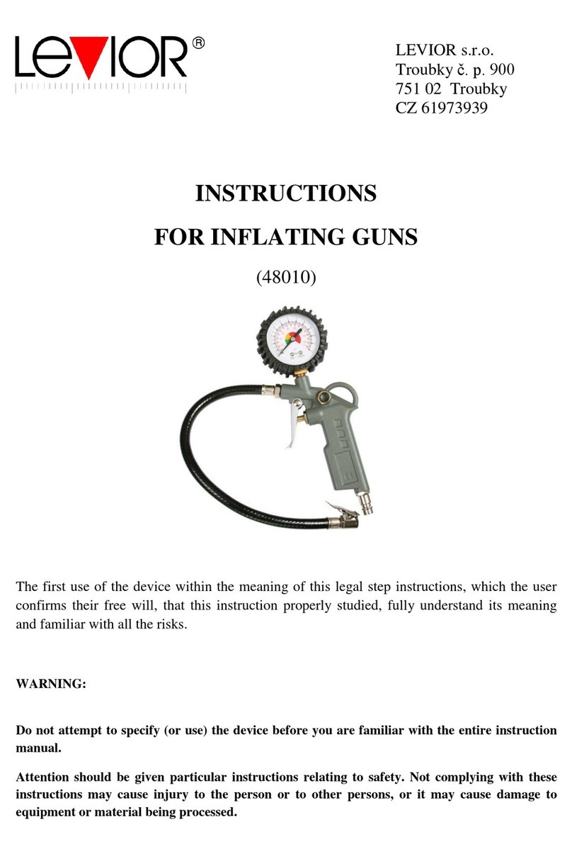
LEVIOR 48010 instructions
