M-system RPPD User manual

RPPD
EM-1693 Rev.7P. 1 / 6
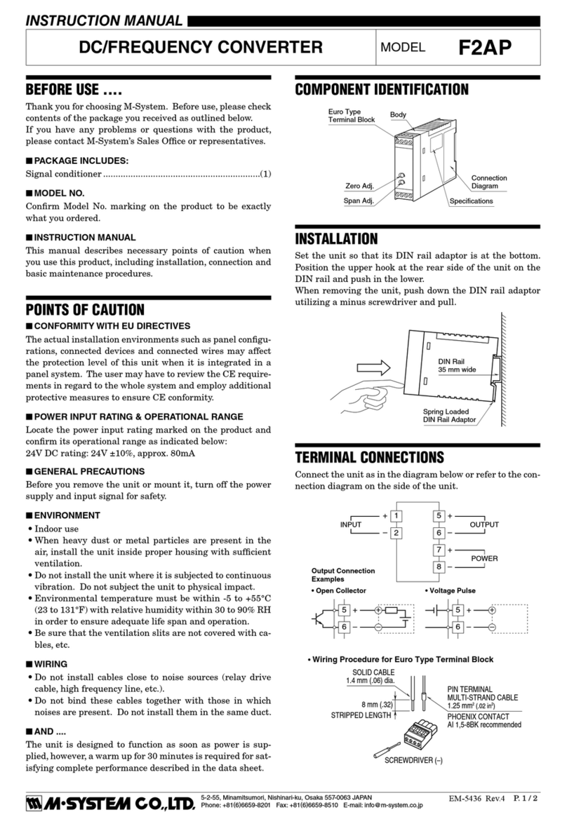
COMPONENT IDENTIFICATION
The shape of base socket may be different
for some models.
■ HOW TO OPEN THE FRONT COVER:
Position your finger on the hook at the top of front cover and
pull.
INSTRUCTION MANUAL
MODEL RPPD
PULSE ISOLATOR
(built-in excitation; rotary encoder use)
BEFORE USE ....
Thank you for choosing M-System. Before use, check the
contents of the package you received as outlined below.
If you have any problems or questions with the product,
please contact M-System's Sales Office or representatives.
■ PACKAGE INCLUDES:
Signal conditioner (body + base socket) ..................... (1)
Ordering Information Sheet ....................................... (1)
■ MODEL NO.
Check that model No. described on specification label is
exactly what you ordered.
■ INSTRUCTION MANUAL
This manual describes necessary points of caution when you
use this product, including installation and connection, hard-
ware setting, and basic maintenance procedures.
This unit is factory adjusted and calibrated according to the
Ordering Information included in the product package. If you
don't need to change the pre-adjusted setting, you can skip
the sections on hardware setting and calibration in this
manual.
POINTS OF CAUTION
■ CONFORMITY WITH CE EMC DIRECTIVE
• Install lightning surge protectors for those wires connected
to remote locations. For 24V DC power supply line, choose a
surge protector with its maximum surge voltage 40V or less
between lines. Recommended M-System model: MDP-D24.
■ POWER INPUT RATING & OPERATIONAL RANGE
• Check the power rating for the unit on the specification label.
85 – 132V AC rating: 85 – 132V, 47 – 66 Hz, approx. 5.5VA
12, 24, and 48V DC ratings: Rating ±10%, approx. 3.3W
110V DC rating: 85 – 150V DC, approx. 3.3W
■ UNPLUGGING THE UNIT
• Before you remove the unit from its base socket or mount it,
turn off the power supply and input signal for safety.
■ ENVIRONMENT
• Indoor use
• When heavy dust or metal particles are present in the air,
install the unit inside proper housing with sufficient ventila-
tion.
• Do not install the unit where it is subjected to continuous
vibration. Do not subject the unit to physical impact.
• Environmental temperature must be within -5 to +60°C (23
to 140°F) with relative humidity within 30 to 90% RH in order
to ensure adequate life span and operation.
■ WIRING
• Do not install cables (power supply, input and output) close
to noise sources (relay drive cable, high frequency line, etc.).
• Do not bind the unit's cables together with cables where
high noise levels are present. Do not install them in the same
duct.
■ AND ....
• The unit is designed to function as soon as power is
supplied, however, a warm up for 10 minutes is required for
satisfying complete performance described in the data sheet.
Body Base Socket
Connection
Diagram Label
Front Cover
Specification
Label
Front Cover (open)
Input Monitor LED PL2
Input Monitor LED PL1
■ FRONT PANEL CONFIGURATION
Clamp
(top & bottom)
DIN Rail
35mm wide
Spring Loaded
DIN Rail Adaptor
Shape and size of the base socket
are slightly different with various
socket types.
INSTALLATION
Detach the yellow clamps located at the top and bottom of the
unit for separating the body from the base socket.
■ DIN RAIL MOUNTING
Set the base socket so that its
DIN rail adaptor is at the bot-
tom. Position the upper hook
at the rear side of
base socket on the DIN rail
and push in the lower. When
removing the socket, push
down the DIN rail
adaptor utilizing a minus
screwdriver and pull.
■ WALL MOUNTING
Refer to the drawings in the
next page.

RPPD
EM-1693 Rev.7P. 2 / 6
5678
21
1110
80 (3.15)
50 (1.97) 107 (4.21)
136 (5.35) [3.3 (.13)]
80 (3.15)
20
(.79)
35.4 (1.39)
40 (1.57)
50 (1.97)
7.8 (.31)
CLAMP
(top & bottom)
DIN RAIL
35mm wide
2–4.5 (.18) dia.
MTG HOLE
25 (.98) deep
11–M3.5
SCREW
•When mounting, no extra space is needed between units.
39
4
Input Connection Examples ■Open Collector
Output Connection Examples
+
–
1
2
+
–
■Voltage Pulse
+
–
1
2
+
–
+
–
10
11
+
–
+
–
10
11
+
–
+
–
OUTPUT 1
1
2
U(+)
V(–) POWER
7
8
+
–
INPUT 1
3
4
+
–
OUTPUT 2
10
11
+
–
INPUT 2
9
6
5
SENSOR EXC.
+
–
OUTPUT 1
1
2
U(+)
V(–) POWER
7
8
+
–
3
4
+
–
5
6
Sensor excitation not provided for RS-422 line driver input.
+
–
OUTPUT 2
10
11
■RS-422 LINE DRIVER INPUT
ROTARY
ENCODER
5
9
6
+
10kΩ
100Ω
100Ω
■Dry Contact
+
–
–
3
4
+
–
Vsns
PWR
■2-Wire Current Pulse
•Built-in Excitation
5
9
6
+
Vsns
2-WIRE
PICK-UP
100Ω
3
4
–
2-WIRE
PICK-UP
•External DC Supply
5
9
6
–
2-WIRE
PICK-UP
+
+
DC SUPPLY
–
100Ω
3
4
–
2-WIRE
PICK-UP
+
+
DC SUPPLY
–
■Voltage Pulse
5
9
6
+
+
–
–
Vsns
PWR
3
4
+
–
–
+
A
φ
B
φ
A
φ
B
φ
■Power Photo MOSFET Relay
•AC Powered
1
2
LOAD
Relay or
Counter
Coil
Varistor or Spark
Quenching Circuit
•DC Powered
1
2
LOAD
Relay or
Counter
Coil
Spark Quenching
Diode
+
–
■RS-422 Line Driver Pulse
2
+
–
+
–
1
+
–
11
+
–
+
–
10
TERMINAL CONNECTIONS
Connect the unit as in the diagram below or refer to the connection diagram label on top of the unit.
■ DIMENSIONS mm (inch)
■ CONNECTION DIAGRAM

RPPD
EM-1693 Rev.7P. 3 / 6
FUNCTION & FEATURES
•Galvanically isolating pulse rate signals from a rotary
encoder
•Maximum input/output frequencies: 100 kHz
•Minimum input pulse width: 5 µsec. (dry contact, voltage/
current pulse input)
•Monitor LED provided to check that input pulses are
provided.
•Accepting a wide variety of input: 0.5 – 50V at the input
terminals
•Pulse logic can be converted.
•RS-422 line driver pulse input acceptable; converted into
dry contact or voltage pulse output.
•For one-shot output, a pulse rise or drop can be selected for
synchronization.
•Output 1 is available with power photo MOSFET relay.
H
L
VOLTAGE PULSE
or
RS-422 LINE DRIVER PULSE
OUTPUT WAVEFORM
OPEN COLLECTOR
or
PHOTO MOSFET RELAY
The pulse width in one-shot means the bold lined section of a pulse waveform.
*Pulse rise for RS-422 line driver pulse can not be detected.
No pulse width conversion
One-shot, detecting input pulse rise
Non
Inverted
VOLTAGE PULSE,
2-WIRE CURRENT PULSE or
RS-422 LINE DRIVER PULSE
DRY CONTACTINPUT WAVEFORM
H
H
L
H
H
L
L
H
L
OFF
ON
L
L
H
One-shot, detecting input pulse drop
H
L
No pulse width conversion
One-shot, detecting input pulse rise
Inverted
H
H
L
H
H
L
L
L
L
H
One-shot, detecting input pulse drop
OFF
ON
No pulse width conversion
One-shot, detecting input pulse rise
Non
Inverted
OFF
ON
OFF
ON
OFF
ON
OFF
ON
OFF
ON
OFF
ON
OFF
ON
OFF
ON
OFF
ON
OFF
ON
OFF
ON
One-shot, detecting input pulse drop
No pulse width conversion
One-shot, detecting input pulse rise
Inverted
One-shot, detecting input pulse drop
*
*
*
*
I/O PULSE LOGIC

RPPD
EM-1693 Rev.7P. 4 / 6
HARDWARE SETTING & CALIBRATION
■ SW1 & 2 FUNCTIONS (SW1: Input 2, SW2: Input 1, SW1-3 and SW2-3 are used commonly to both inputs.)
■ INPUT FILTER
The tables below show the maximum frequency which can
pass through the filter when the sensitivity level is set to 2V.
The frequency may change according to the sensitivity level.
After turning the filter ON, check that the PL1 and PL2 blink
according to the input signals. If they do not, readjust the
sensitivity according to the instructions in the following
section.
•Noise Filter Type 1 (SW1/2–5 = ON)
DC Coupling AC Coupling
(SW1/2–8 = ON) (SW1/2–8 = OFF)
V p-p (V)
MAX. FREQ. (Hz)
V p-p (V)
MAX. FREQ. (Hz)
5 69 5 22
12 35 12 65
24 89 24 112
•Noise Filter Type 2 (SW1/2–6 = ON)
DC Coupling AC Coupling
(SW1/2–8 = ON) (SW1/–8 = OFF)
V p-p (V)
MAX. FREQ. (Hz)
V p-p (V)
MAX. FREQ. (Hz)
5 1220 5 256
12 329 12 664
24 851 24 1090
Sensitivity Adj. (V
H
)
Sensitivity Adj. (V
L
)
Sensor Excitation Adj.
O
N
2
1
3
4
5
6
7
8
Set each switch referring
to the table below.
O
N
2
1
3
4
5
6
7
8
SW2
SW1
Set each switch referring
to the table below.
(front cover open)
Input Monitor LED PL1
Input Monitor LED PL2
There is no need of hardware adjustment
for RS-422 line driver pulse input.
Unnecessary switches or LEDs are not provided.
SWITCH INPUT MODEL SUFFIX CODE
NO. SW FUNCTION A B C D H
SW1,2
– 1 ON with dry contact input (model suffix: A) ON OFF OFF OFF OFF
2ON with 2-wire current pulse input (model suffix: H) OFF OFF OFF OFF ON
3
SW1–3: Adjustable range of sensitivity level for V
L
(ON: 0 – 10V, OFF: 0 – 5V)
ON or OFF OFF
ON or OFF
OFF
SW2–3: Adjustable range of sensitivity level for V
L
(ON: 0 – 10V, OFF: 0 – 5V)
(required level)
(required
Refer to the section "SENSITIVITY ADJUSTMENT". level)
4Always ON ON
5Noise filter Type 1 (ON: with, OFF: without)
6Noise filter Type 2 (ON: with, OFF: without)
7Attenuator for input signal (ON: with, OFF: without) OFF * OFF * OFF OFF * OFF
Input voltage is attenuated to half the original amplitude with this switch ON.
(one-third for the model number suffix code A.)
8Input pulse sensing method (ON: DC coupled, OFF: AC coupled) ON
Turn this switch off with a 10V or greater offset.
*Set to ON with excitation voltage ≥24V.
ON or OFF according to the noise level. Refer
to the tables below for the max. frequency
which can pass through the filter.

RPPD
EM-1693 Rev.7P. 5 / 6
■ SENSITIVITY ADJUSTMENT
You can change the detection level with the sensitivity adj.
located behind the front cover. The VHdetermines the pulse
rise and the VLdetermines the pulse fall. With SW1/2-7 set
to ON, the input signal is scaled down by 1/2 (1/3 for the model
number suffix code A). Be sure that the sensitivity levels are
also scaled down by 1/2 (1/3 for the model number suffix code
A). See the Ordering Information Sheet included in the
package for the factory settings.
For the RS-422 line driver pulse input, there is no need of
adjustment because a line receiver conforming with the RS-
422 standard is incorporated.
•How to Change the Sensitivity
A voltmeter of class 0.5 or better accuracy with pointed
probes is required.
1) Connect the negative probe of voltmeter to the terminal 4
(6) of base socket. See the figure to the right.
2) If you need a noise filter, turn on the SW1/2–5 or SW1/2–
6.
3) Connect the positive probe to the test hole No. 2 and turn
the VHpotentiometer until the meter shows desired
value.***
4) Connect the positive probe to the test hole No. 3 and turn
the VLpotentiometer until the meter shows desired
value.***
5) Apply input signal and check that input monitor LED
(PL1 or PL2) blinks according to the input signal.****
***For the VH(VL) sensitivity level less than 5V, turn off the
SW2–3 (SW1-–3). For less than 10V, turn on the SW2–3
(SW1–3).
The voltage values approx. half the amplitude are recom-
mended for normal use.
You had better have a reasonable span between VHand VLin
order to prevent noise interference.
****If the LED does not blink correctly, the sensitivity level
may be out of the pulse amplitude. Check the offset, ampli-
tude, etc. and go through the adjustment procedure again.
Amplitude
Vinp-p
t
Volts
Sensitivity Level
Input Monitor LED
V
H
V
L
VOLTAGE PULSE (example)
Amplitude
Vinp-p
t
Volts
The voltage which remains across
the terminals with contact ON
V
H
Exc.
V
L
0V
OFF
ON
0V
DRY CONTACT (example)
1
2
+
3
+
V
H
V
L
–
Connect to
Terminal 4 (6)
of the base
socket.
Voltmeter
Test Holes
Input Monitor LED (PL1)
Sensitivity Adj. (VH)
Sensitivity Adj. (VL)
Input Monitor LED (PL2)
(front cover open)

RPPD
EM-1693 Rev.7P. 6 / 6
■ SENSOR EXCITATION ADJUSTMENT
You can change the sensor excitation voltage with the sensor
excitation adj. located behind the front cover. If you need to
change it, check that the required current is within the
specification.
•How to Change the Excitation
A voltmeter and ammeter of class 0.5 or better accuracy are
required.
1) Connect the voltmeter across the terminals 9 – 6.
2) Connect the ammeter to terminal 9.
3) Turn the potentiometer until the meter shows the desired
value.
Check that the current value indicated on the ammeter is
within the allowable limit. If the value is greater than the
limit, lower the voltage value or connect a separate power
source. Otherwise, the transmitter may fail.
25
5
12
24
60 120
CURRENT (mA)
VOLTAGE (V)
Voltage (V) ×Current (A) ≤600mW
MAINTENANCE
■ TROUBLESHOOTING
Refer to the flow chart below.
V
A
Ammeter
Voltmeter
+
–OUTPUT 1
1
2
U(+)
V(–) POWER
7
8
+
–
INPUT 1 3
4
+
–OUTPUT 2
10
11
+
–
INPUT 2
9
6
5
SENSOR
EXC.
Checking & Maintenance
To TERMINAL CONNECTIONS (P.2)
End of Checking
Is the power supply voltage (Terminal 7 – 8) at the proper level?
Is the load connected to sensor excitation within allowance?
Check that the load resistance meets the described specification.
All wires connected
according to the connection
diagram?
Is the PL1 blinking
according to the input signal?
To HARDWARE SETTING & CALIBRATION,
Refer to the sensitivity adjustment. (P.5)
Check the input connection again and make
sure that the input matches descriptions
in the ordering information sheet.
No
Yes
No
To HARDWARE SETTING & CALIBRATION,
Refer to the SW1 setting. (P.4)
No
Yes
Is the PL2 blinking
according to the input signal?
Yes
Yes
M-SYSTEM WARRANTY
M-System warrants such new M-System product which it manufactures to be free from defects in materials and workmanship during the 36-month period following the date that such
productwasoriginallypurchasedifsuchproducthasbeenusedundernormaloperatingconditionsandproperlymaintained,M-System'ssoleliability,andpurchaser'sexclusiveremedies,
under this warranty are, at M-System's option, the repair, replacement or refund of the purchase price of any M-System product which is defective under the terms of this warranty. To
submit a claim under this warranty, the purchaser must return, at its expense, the defective M-System product to the below address together with a copy of its original sales invoice.
THIS IS THE ONLY WARRANTY APPLICABLE TO M-SYSTEM PRODUCT AND IS IN LIEU OF ALL OTHER WARRANTIES, EXPRESS OR IMPLIED, INCLUDING ANY IMPLIED
WARRANTIES OF MERCHANTABILITY OR FITNESS FOR A PARTICULAR PURPOSE. M-SYSTEM SHALL HAVE NO LIABILITY FOR CONSEQUENTIAL, INCIDENTAL OR
SPECIAL DAMAGES OF ANY KIND WHATSOEVER.
M-System Co., Ltd., 5-2-55, Minamitsumori, Nishinari-ku, Osaka 557-0063 JAPAN, Phone: (06) 6659-8201, Fax: (06) 6659-8510, E-mail: [email protected]
Table of contents
Other M-system DC Drive manuals


