R30NCIE1
5-2-55, Minamitsumori, Nishinari-ku, Osaka 557-0063 JAPAN
Phone: +81(6)6659-8201 Fax: +81(6)6659-8510 E-mail: info@m-system.co.jp
EM-9020 Rev.3 P. 6 / 13
0
0
RX(n+0)
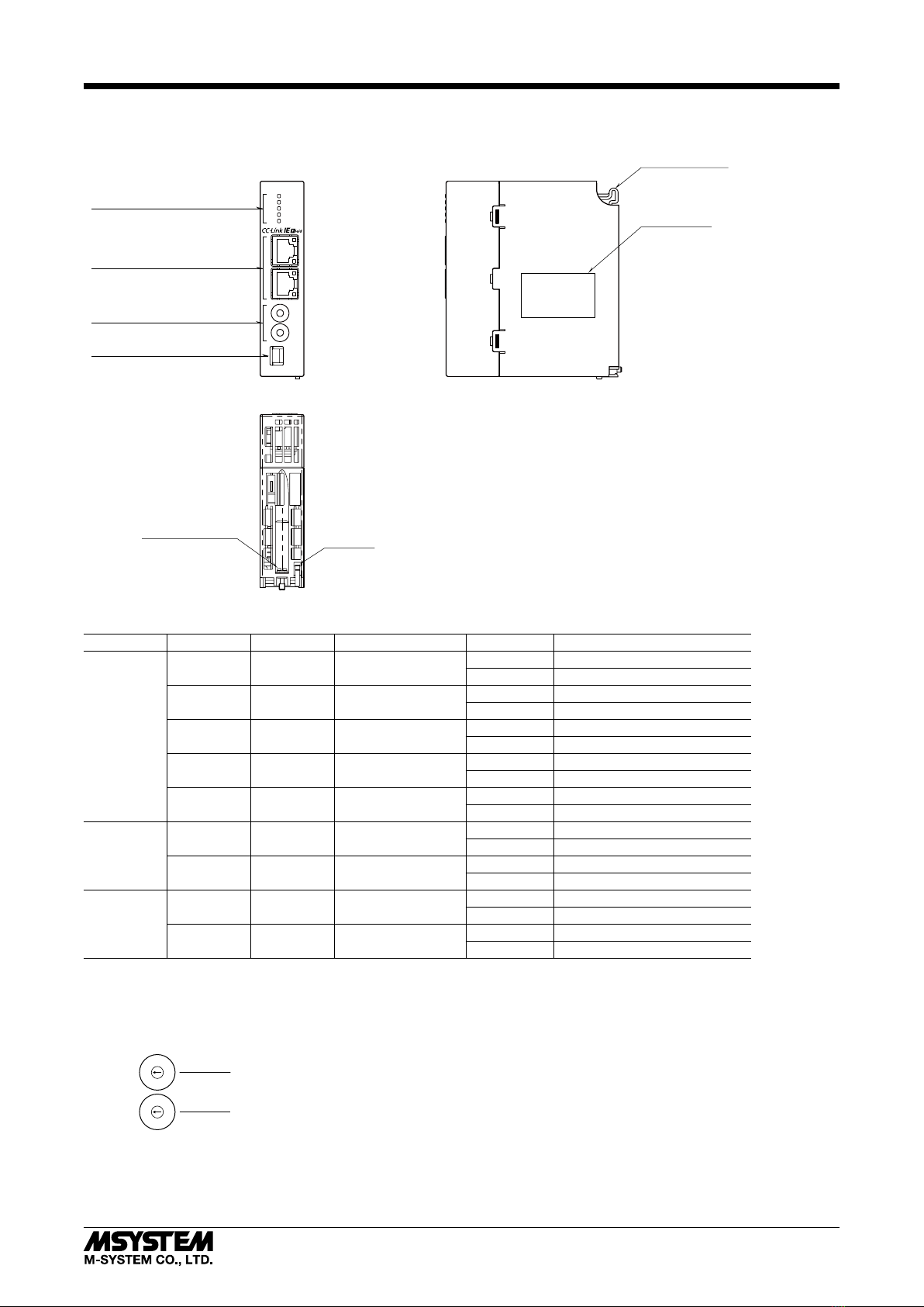
Remote READY
Module Status (R30 Series)
Module Status (R3 Series)
Error Status (R30 Series)
Data Error Status (R30 Series)
Error Status (R3 Series)
Data Error Status (R3 Series)
15
2
1
A
B
C
D
E
3
F
9
8
7
6
5
4
RX(n+3)
RX(n+4)
RX(n+5)
RX(n+6)
RX(n+2)
RX(n+1)
RX(n+7) Unused
• RX(n+0)0 to 7 is reservation area, RX(n+0) is used as Ready signal, the bit is “1” when this module is in normal.
RX(n+0)8 to A, RX(n+0)C to F are not used.
• Module Status
RX(n+1)0 to RX(n+1)F indicate whether individual I/O modules of R30 series are mounted or not .
RX(n+2)0 to RX(n+2)F indicate whether individual I/O modules of R3 series are mounted or not.
The bit corresponding to the mounted slot turns to “1”, and the unmounted slot to “0”.
• Error Status
RX(n+3)0 to RX(n+3)F indicate error status for each module of R30 series.
The bit corresponding to such module turns to “1”, as described below.
R30X16(under development) input power in error or disconnected.
R30Y16(under development) output current in error (e.g. load unconnected)
RX(n+4)0 to RX(n+4)F indicate error status for each module of R3 series.
The bit corresponding to such module turns to “1”, as described below.
R3-TSx, R3-RSx, R3-US4 input burnout
R3-DA16A input power in error or disconnected
R3-YSx output current error (e.g load unconnected)
R3-PC16A external power supply in error or disconnected
• Data Error Status
RX(n+5)0 to RX(n+5)F indicate data error status for each module of R30 series.
The bit corresponding to such module turns to “1”, as described below.
Input value is out of -15% to 115%
R30TS4, R30RS4, R30USx input burnout
RX(n+6)0 to RX(n+6)F indicate error status for each module of R3 series.
The bit corresponding to such module turns to “1”, as described below.
Input value is out of -15% to 115%
In the case of R3-US4 (voltage input) input level out of -10% to 110%.
RX(n+1)0, RX(n+3)0, RX(n+5)0 R30 series slot 1
RX(n+1)1, RX(n+3)1, RX(n+5)1 R30 series slot 2
RX(n+1)2, RX(n+3)2, RX(n+5)2 R30 series slot 3
:
RX(n+1)F, RX(n+3)F RX(n+5)F R30 series slot 16
RX(n+2)0, RX(n+4)0, RX(n+6)0 R3 series extension slot 1
RX(n+2)1, RX(n+4)1, RX(n+6)1 R3 series extension slot 2
RX(n+2)2, RX(n+4)2, RX(n+6)2 R3 series extension slot 3
:
RX(n+2)F, RX(n+4)F, RX(n+6)F R3 series extension slot 16
Link devices other than the above are not in use.