manuals.online logo
Brands
  1. Home
  2. •
  3. Brands
  4. •
  5. M-system
  6. •
  7. Network Hardware
  8. •
  9. M-system RGP30 User manual

M-system RGP30 User manual

Other M-system Network Hardware manuals

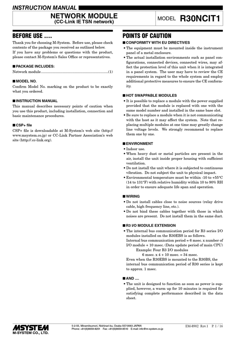
M-system R30NCIT1 User manual

M-system

M-system R30NCIT1 User manual

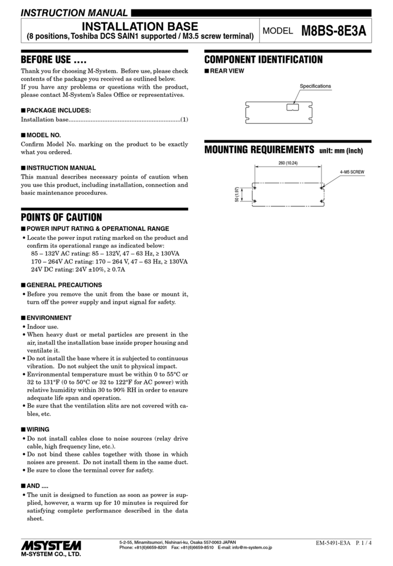
M-system M8BS-8E3A User manual

M-system

M-system M8BS-8E3A User manual

M-system M8BS2-162 User manual

M-system

M-system M8BS2-162 User manual

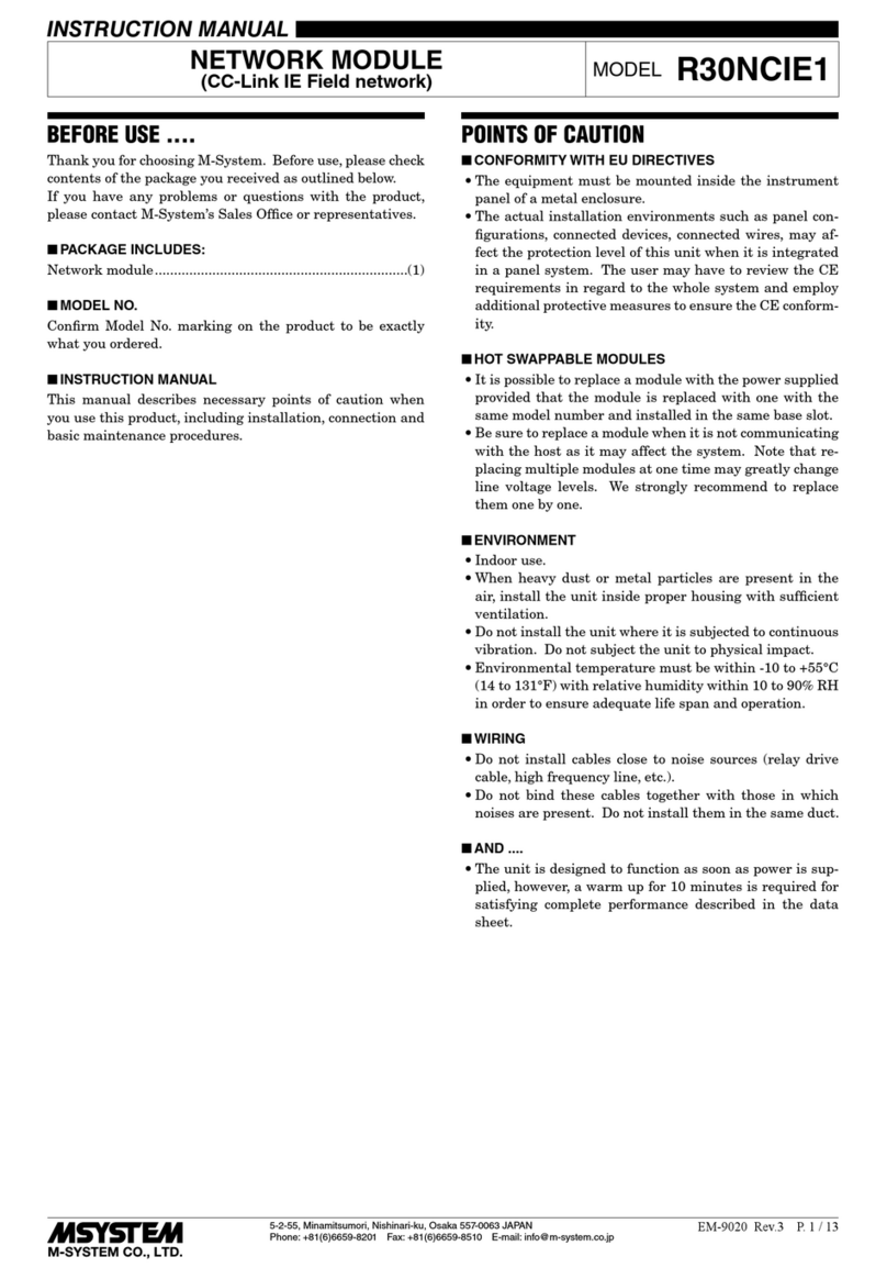
M-system R30NCIE1 User manual

M-system

M-system R30NCIE1 User manual

M-system M5XSBS User manual

M-system

M-system M5XSBS User manual

Popular Network Hardware manuals by other brands

socomec SNMP Card II quick start guide

socomec

socomec SNMP Card II quick start guide

NVR SYSTEMS 4-CH user manual

NVR SYSTEMS

NVR SYSTEMS 4-CH user manual

Draytek VigorSwitch G1240 quick start guide

Draytek

Draytek VigorSwitch G1240 quick start guide

Westermo TD-34 LV installation manual

Westermo

Westermo TD-34 LV installation manual

LaCie Network Space MAX Quick install guide

LaCie

LaCie Network Space MAX Quick install guide

ZoneVu ZSI-450-IP Installation guide & user manual

ZoneVu

ZoneVu ZSI-450-IP Installation guide & user manual

QNAP Turbo NAS Application notes

QNAP

QNAP Turbo NAS Application notes

OpenEye MV Series quick start guide

OpenEye

OpenEye MV Series quick start guide

Huawei SmartAX MT880a quick start guide

Huawei

Huawei SmartAX MT880a quick start guide

Proxim Tsunami QuickBridge 2454-R installation guide

Proxim

Proxim Tsunami QuickBridge 2454-R installation guide

Bay Networks CLAM quick start guide

Bay Networks

Bay Networks CLAM quick start guide

Innodisk SATADOM-SH 3SE Series manual

Innodisk

Innodisk SATADOM-SH 3SE Series manual

Cisco CGR 1000 Series Getting connected guide

Cisco

Cisco CGR 1000 Series Getting connected guide

Matrix Switch Corporation MSC-HD161DEL product manual

Matrix Switch Corporation

Matrix Switch Corporation MSC-HD161DEL product manual

National Instruments NI 653x user manual

National Instruments

National Instruments NI 653x user manual

B&B Electronics ZXT9-IO-222R2 product manual

B&B Electronics

B&B Electronics ZXT9-IO-222R2 product manual

Yudor YDS-16 user manual

Yudor

Yudor YDS-16 user manual

D-Link ShareCenter DNS-320L datasheet

D-Link

D-Link ShareCenter DNS-320L datasheet

manuals.online logo
manuals.online logoBrands
  • About & Mission
  • Contact us
  • Privacy Policy
  • Terms and Conditions

Copyright 2025 Manuals.Online. All Rights Reserved.

5-2-55, Minamitsumori, Nishinari-ku, Osaka 557-0063 JAPAN
Phone: +81(6)6659-8201 Fax: +81(6)6659-8510 E-mail: info@m-system.co.jp
EM-8581-A P. 1 / 4
INSTRUCTION MANUAL
REMOTE GRAPHIC PANEL
(with HDMI output) MODEL RGP30
BEFORE USE ....
Thank you for choosing M-System. Before use, please check
contents of the package you received as outlined below.
If you have any problems or questions with the product,
please contact M-System’s Sales Office or representatives.
This product is for use in general industrial environments,
therefore may not be suitable for applications which require
higher level of safety (e.g. safety or accident prevention sys-
tems) or of reliability (e.g. vehicle control or combustion con-
trol systems).
For safety, installation and maintenance of this product
must be conducted by qualified personnel.
■PACKAGE INCLUDES:
Remote Graphic Panel ........................................................(1)
■MODEL NO.
Confirm Model No. marking on the product to be exactly
what you ordered.
■INSTRUCTION MANUAL
This manual describes necessary points of caution for han-
dling this product and specifically for installation, wiring,
and basic maintenance of the product.
For detailed operation, refer to Users Manual (EM-8581-B)
which is downloadable at M-System’s web site (http://
www.m-system.co.jp).
POINTS OF CAUTION
■POWER INPUT RATING & OPERATIONAL RANGE
• Locate the power input rating marked on the product and
confirm its operational range as indicated below:
24V DC rating: 24V ±10%, approx. 18W
• Provide back-up power supply using UPS.
■GENERAL PRECAUTIONS
• Before removing the unit or mount it, turn off the power
supply for safety.
• Before removing the terminal block or mount it, turn off
the power for safety.
■ENVIRONMENT
• Indoor use.
• Do not install the unit where heavy dust or metal parti-
cles are present in the air.
• Avoid a place where the unit may be subjected to continu-
ous vibration or shock.
• Environmental temperature must be within -10 to 50°C
(14 to 122°F) with relative humidity within 30 to 90% RH
in order to ensure adequate life span and operation.
• Use in clean atmosphere. Do not expose the unit for a
prolonged period of time to an atmosphere containing va-
por of organic solvent or acidic gases, such as paint thin-
ner, acetone, formalin or sulfurous acid gas.
• Do not expose the unit to direct sunlight.
■WIRING
• Do not install cables close to noise sources (relay drive
cable, high frequency line, etc.).
• Do not bind these cables together with those in which
noises are present. Do not install them in the same duct.
■AND ....
• The unit is designed to function as soon as power is sup-
plied, however, a warm up for 10 minutes is required for
satisfying complete performance described in the data
sheet.
The terms HDMI, HDMI High-Definition Multimedia Interface, and the HDMI Logo
are trademarks or registered trademarks of HDMI Licensing Administrator, Inc.
RGP30
5-2-55, Minamitsumori, Nishinari-ku, Osaka 557-0063 JAPAN
Phone: +81(6)6659-8201 Fax: +81(6)6659-8510 E-mail: info@m-system.co.jp
EM-8581-A P. 2 / 4
COMPONENT IDENTIFICATION
■FRONT PANEL
USB Ports
HDMI Output Port
RGP30
POWER
RUN
ERROR
HDMI
SHUTDOWN
USB
ACT
+24V
0V
NC
NC
FE
LNK
Status Indicator LED
Shutdown Button
RJ-45 modular jack
for Ethernet
Power Supply connector
■STATUS INDICATOR LED
LED
COLOR
FUNCTION
POWER Green ON when power is on
OFF when power is off
RUN Green ON before shutdown
OFF after shutdown
ERROR Red
Blinks three times at start-up
OFF at normal operation
Blinking in error
■ETHERNET INDICATOR LED
LED COLOR FUNCTION
ACT Amber ON during communication
LNK Green ON when link is established
■SHUTDOWN BUTTON
Never fail to shutdown the RGP30 unit when removing the
power supply.
1) Hold down Shutdown button for 3 seconds to start shut-
down process.
2) Confirm that the RUN LED turns OFF as shutdown is
complete before removing the power supply.
■TERMINAL ASSIGNMENT
NO. ID FUNCTION
1 24V Power supply (24 V DC)
2 0V Power supply (0 V DC)
3 NC Not used
4 NC Not used
5 FE Functional earth
1
2
3
4
5
RGP30
5-2-55, Minamitsumori, Nishinari-ku, Osaka 557-0063 JAPAN
Phone: +81(6)6659-8201 Fax: +81(6)6659-8510 E-mail: info@m-system.co.jp
EM-8581-A P. 3 / 4
INSTALLATION
■INSTALLATION
1) Set the unit such that its slider is at the bottom.
2) Hook the upper hook at the rear side of the unit onto the
DIN rail.
3) Push the lower part of the unit in the direction of the arrow.
4) Push up the slider so that the unit is fixed.
5) When removing the unit, push down the slider with a tool
such as a flat-blade screwdriver and pull the lower part of
the unit.
Hook
Slider
■MOUNTING DIRECTION
The unit must be mounted in an upright position as shown below.
Mounting the unit in other orientations may cause the internal temperature to rise, resulting in shorter product life and/or
deteriorated performance.
UP
DOWN
■MOUNTING INSIDE CONTROL PANEL unit: mm (inch)
- Secure sufficient ventilation space.
- Do not mount the unit right above devices which radiate great heat
such as heaters, transformers, or resistors.
- Provide adequate maintenance space above and below the unit.
Panel ceiling or wiring conduit (clearance of ≤ 50 mm or 2 in.)
Panel bottom or wiring conduit (clearance of ≤ 50 mm or 2 in.)
50 (2) 50 (2)
50 (2)
40 (1.6)
RGP30
5-2-55, Minamitsumori, Nishinari-ku, Osaka 557-0063 JAPAN
Phone: +81(6)6659-8201 Fax: +81(6)6659-8510 E-mail: info@m-system.co.jp
EM-8581-A P. 4 / 4
TERMINAL CONNECTIONS
Connect the unit as in the diagram below.
■EXTERNAL DIMENSIONS unit: mm (inch)
110 (4.33)
DIN RAIL
(35 mm wide)
[5 (.19)]
110 (4.33)
128 (5.04)
50 (1.97)
■CONNECTION DIAGRAM
Caution: FE terminal is NOT a protective conductor terminal.
1
2
5
24V
0V
FE
POWER SUPPLY
RJ-45 MODULAR JACK
Ethernet
USB PORT
HDMI OUTPUT PORT
SHUTDOWN BUTTON
USB
HDMI
WIRING INSTRUCTIONS
■APPLICABLE CONNECTOR
FKCN2,5 / 5–STF–5,08 (Phoenix Contact) (comes with the unit)
■APPLICABLE WIRE
Applicable wire size: 0.2 – 2.5 mm2
Stripped length: 10 mm
Recommended solderless terminal
• AI0,25-10YE 0.25 mm2(Phoenix Contact)
• AI0,34-10TQ 0.34 mm2(Phoenix Contact)
• AI0,5-10WH 0.5 mm2(Phoenix Contact)
• AI0,75-10GY 0.75 mm2(Phoenix Contact)
• AI1-10RD 1.0 mm2(Phoenix Contact)
• AI1,5-10BK 1.5 mm2(Phoenix Contact)
• AI2, 5-10BU 2.5 mm2(Phoenix Contact)