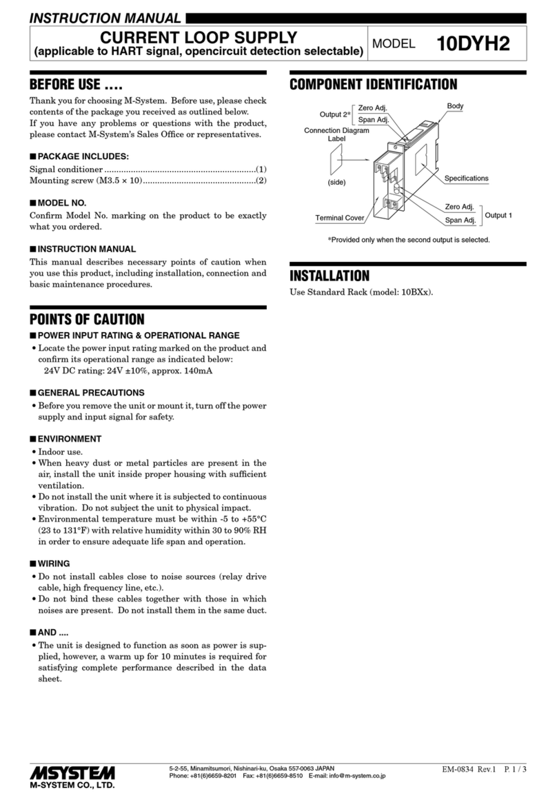
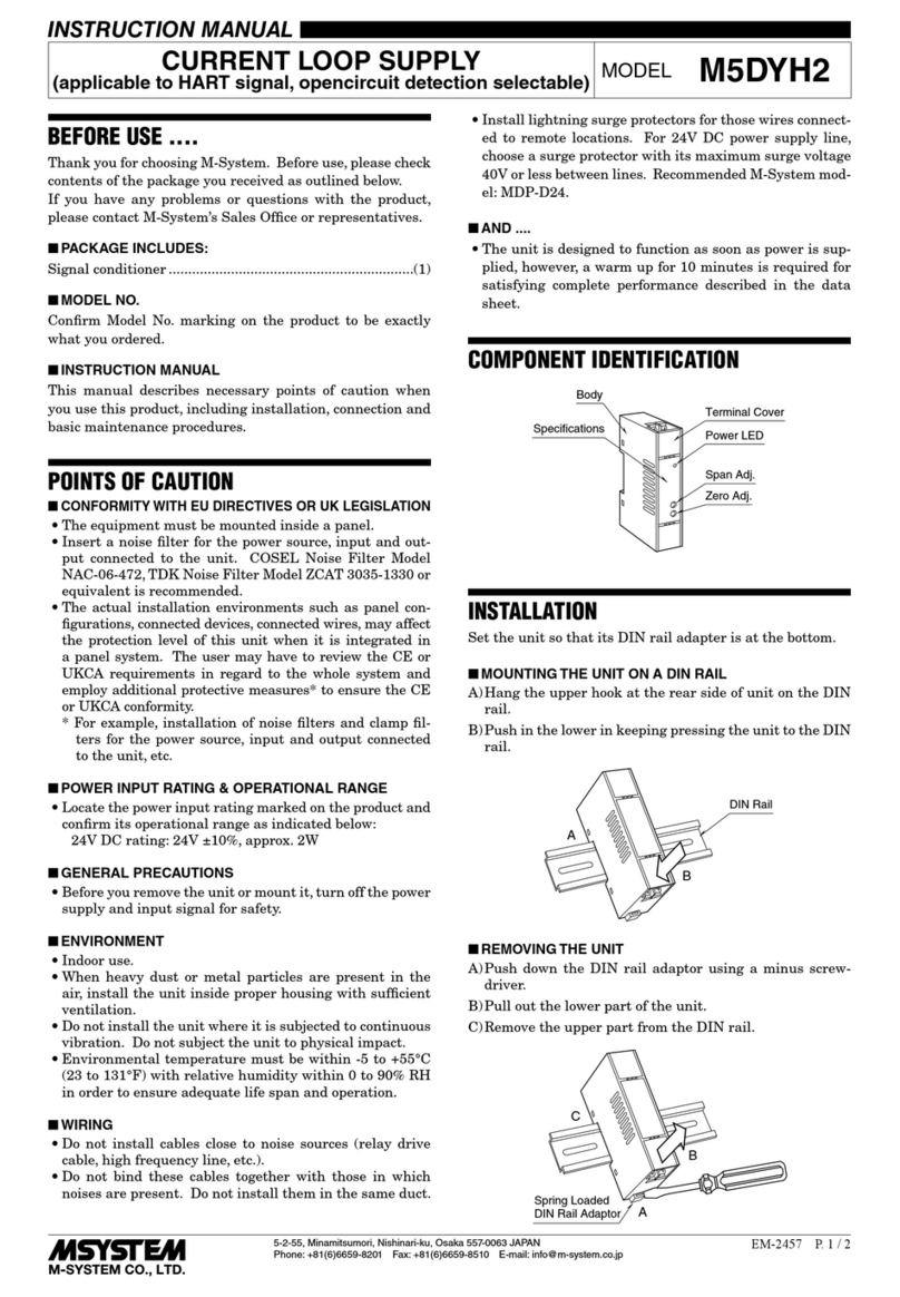
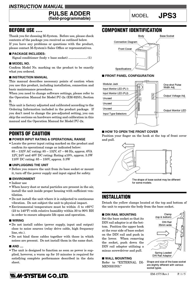
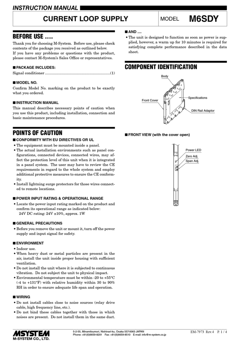
POWER SUPPLY MODULE MODEL R5-PS1
INSTRUCTION MANUAL
BEFORE USE ....
Thank you for choosing M-System. Before use, please check
contents of the package you received as outlined below.
If you have any problems or questions with the product,
please contact M-System’s Sales Office or representatives.
nPACKAGE INCLUDES:
Power supply module .................................................. (1)
nMODEL NO.
Confirm that the Model No.marking on the product is exactly
what you ordered.
nINSTRUCTION MANUAL
This manual describes necessary points of caution when you
use this product, including installation, connection and basic
maintenance procedures.
POINTS OF CAUTION
nCONFORMITY WITH EU DIRECTIVES
•ThisequipmentissuitableforuseinInstallationCategory
II (power input), Measurement Category II (RUN contact
output) and Polution Degree 2. Reinforced insulation (in-
ternal power or RUN contact output to power input to FG:
300V) and basic insulation (internal power to RUN contact
output: 300V) are maintained. Prior to installation, check
that the insulation class of this unit satisfies the system
requirements.
•Theequipmentmustbemountedinsideapanel.
•Insertanoiselterforthepowersourceconnectedtothe
unit. Densei-Lambda Noise Filter Model MZS-1206-33 or
equivalent is recommended.
•Theactualinstallationenvironmentssuchaspanelcon-
figurations, connected devices and connected wires may
affect the protection level of this unit when it is integrated
in a panel system. The user may have to review the CE
requirements in regard to the whole system and employ
additional protective measures to ensure CE conformity.
nPOWER INPUT RATING & OPERATIONAL RANGE
•Checkthepowerratingfortheunitonthespecicationlabel.
AC power: 85 – 132V or 170 – 264V, 47 – 66 Hz,
approx. 90VA
DC power: 24V ±10%, approx. 45W, approx. 1.8A
nUNPLUGGING THE UNIT
•Beforeyouremovetheunitfromitsbaseormountit,turn
off the power supply for safety.
nENVIRONMENT
•Indooruse
•When heavy dust or metal particles are present in the
air, install the unit inside proper housing with sufficient
ventilation.
•Donotinstalltheunitwhereitissubjectedtocontinuous
vibration.Donotsubjecttheunittophysicalimpact.
•Environmentaltemperaturemustbewithin-10to+55°C
(14to131°F)withrelativehumiditywithin30to90%RH
in order to ensure adequate life span and operation.
nWIRING
•Donotinstallcablesclosetonoisesources(relaydrivecable,
high frequency line, etc.).
•Donotbindthesecablestogetherwiththoseinwhichnoises
are present. Do not install them in the same duct.
nRUN CONTACT OUTPUT
•FunctionofRUNcontactoutput
During a Network Module communicates normally with
a master device (PLD or PC etc.), RUN contact output of
Power Supply Module turns ON.
•Whenusingwithdualredundantcommunicationortwo
system.
During both Network Module or one of them communicates
normally with a master device (PLD or PC etc.), RUN contact
output of Power Supply Module turns ON.
•WhenusingR5-PSwithredundantortwosystem.
RUN contact output works in same function for both cases.
However, when I/O capacity code of installation base is
"05:5 slots (single network module)" or "09: 9 slots (single
network module)",the RUN contact output of Power Supply
Module installed in a Extender Power Module Base (model:
R5-EX1) is not available.
nAND ....
•Theunitisdesignedtofunctionassoonaspowerissupplied,
however,a warm up for 10 minutes is required for satisfying
complete performance described in the data sheet.
INSTALLATION
Use the Installation Base (model: R5-BSx) or the Extender
Power Module Base (model: R5-EX1).
In order to separate the Power Supply Module from a base,
push the recess at the center of the locking clamp (See below)
with a minus screwdriver.
Recess
