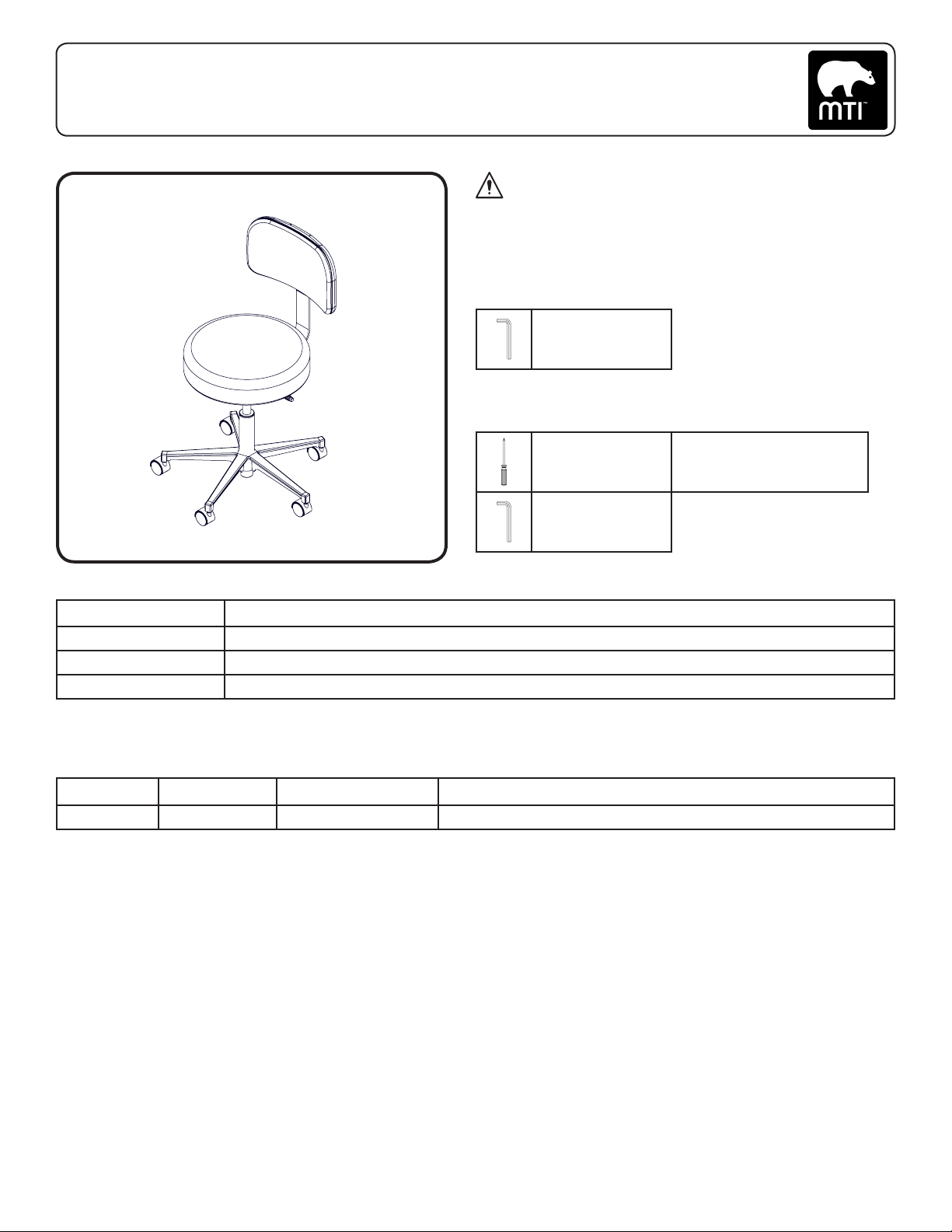
8 Instruction Guide | 322/323/324
073168 Rev A
3655 W Ninigret Drive, Salt Lake City, Utah, 84104-6572
(800) 924-4655 • (801) 875-4999 • Fax (801) 952-0548
www.mti.net
© MTI, Inc. All rights reserved.
MTI reserves the right to make any
product changes without notice.
Strength in patient care.™
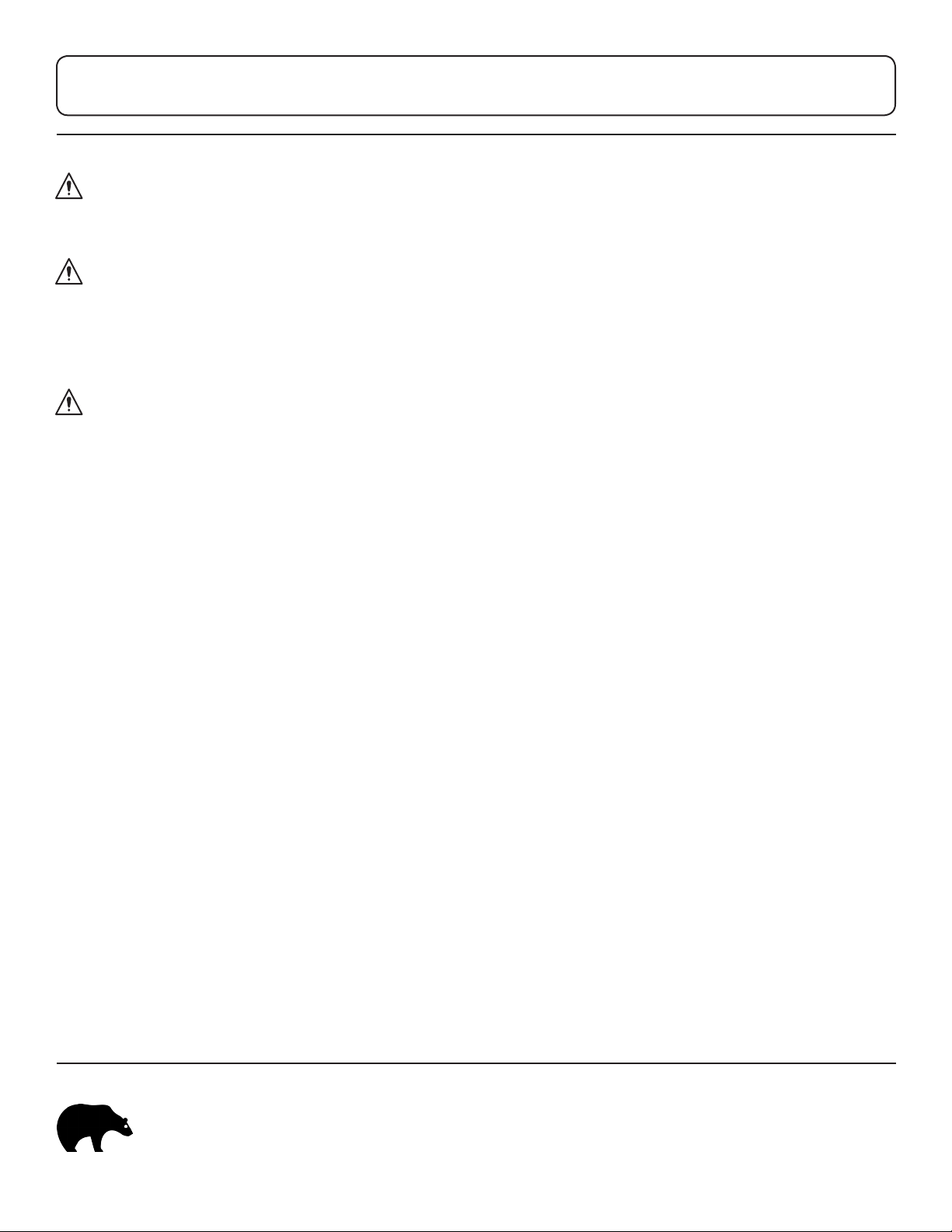
WARNING/AVERTISSEMENT
No modification of this equipment is allowed.
Aucune modification de cet équipement est autorisé.
WARNING/AVERTISSEMENT
Assure equipment, patient, and other objects are in safe
condition before operating the equipment.
Assurer l’appareil, patient, et d’autre objets sont dans un état
sûr avant d’utiliser l’appareil.
WARNING/AVERTISSEMENT
This product contains chemicals known to the State of
California to cause cancer and/or birth defects or other
reproductive harm. See http://www.mti.net/FAQs.aspx for
details on California Proposition 65.
Ce produit contient des produits chimiques reconnus
par l’État de Californie pour causer le cancer et / ou
des anomalies congénitales ou d’autres problèmes de
reproduction. Voir http://www.mti.net/FAQs.aspx pour plus de
détails sur la California Proposition 65.
Cleaning and Disinfection
See “MTI Cleaning Solution Recommendation Letter” for
more details on disinfecting solutions which have been
tested on MTI’s products. It is available for download at
http://www.mti.net/downloads.aspx in the Product Support
Bulletins folder, found under the Resources tab on our
website. In the U.S. & Canada, call (888) 520-4998, or
International, call (801) 875-4998 to request a copy.
Painted and Plastic Surfaces
All painted metal parts have been electrostatically painted
and the paint is baked on for durability. Weekly, those
surfaces should be wiped down with a quality grade
cleaner and a soft cloth or a damp cloth with mild soap.
Upholstery
Upholstery should be cleaned weekly with a mild liquid
soap and water mixture. Afterwards, wipe upholstery with a
clean damp cloth.
Calls for Service
(888) 520-4998 | International (801) 875-4998
LIMITED WARRANTY
Medical Technology Industries, Inc. (hereinafter referred to as MTI), shall
repair or replace products of its manufacture, which prove to be defective
in material and/or workmanship for a period of twelve (12) months from
the date of shipment to the customer (the “Warranty Period”). MTI will,
at its option, provide parts to the customer or repair the defective part
at MTI’s factory or authorized repair facility. Except as it may otherwise
specifically agree in writing, MTI shall not be liable for transportation
or labor charges for repairs or adjustments or other work done on any
of its products by MTI’s authorized dealers or service organizations.
Customer shall notify MTI of any alleged claim or defect within
fourteen (14) days from the date customer discovers, or upon
reasonable inspection should have discovered, such alleged claim or
defect (but in any event before the expiration of the Warranty Period).
All repair parts are warranted for Ninety (90) calendar days from
the date of shipment to the customer. Warranty is non-cumulative.
This warranty does not apply to any part or product which upon examination
by MTI or its authorized agents indicates the product has been repaired or
altered in any way by persons other than MTI or its authorized agents, has
been misused, abused or used in a manner contrary to any instructions
issued by MTI. Any parts or products claimed under this warranty must
be properly packaged by customer and returned to MTI’s factory with no
liability to MTI for the parts, products or transportation charges thereon.
In no event, shall MTI have any liability for consequential, indirect,
incidental, special, exemplary, punitive or enhanced damages, lost profits
or diminution in value arising out of or relating to a product defect or
the repair or replacement of any products manufactured or sold by it.
THE FOREGOING LIMITED WARRANTY IS MADE IN LIEU OF ALL
WARRANTIES EXPRESSED OR IMPLIED, AND MTI MAKES NO OTHER
WARRANTY WHATSOEVER WITH RESPECT TO THE PRODUCTS
INCLUDING BUT NOT LIMITED TO, ANY IMPLIED WARRANTY OR
MERCHANTABILITY OR FITNESS FOR A PARTICULAR PURPOSE.