M-TI DUCAR DLG4000iSE User manual

USER MANUAL
0RGHO'/*L6(
MTI Canada
Tél. / tel.: 418 839-4127
Français: 1 800 463-4398
English: 1 800 463-7205
Téléc. / Fax: 1 800 363-7157
Distribué par / Distributed by :

DISCLAIMERS:
(SSPUMVYTH[PVUPSS\Z[YH[PVUZHUKZWLJPÄJH[PVUZPU[OPZTHU\HSHYLIHZLKVU[OLSH[LZ[PUMVYTH[PVUH]HPSHISLH[
[OL[PTLVMW\ISPZOPUN;OLPSS\Z[YH[PVUZ\ZLKPU[OPZTHU\HSHYLPU[LUKLKHZYLWYLZLU[H[P]LYLMLYLUJL]PL^ZVUS`
4VYLV]LYILJH\ZLVMV\YJVU[PU\V\ZWYVK\J[PTWYV]LTLU[WVSPJ`^LTH`TVKPM`PUMVYTH[PVUPSS\Z[YH[PVUZHUKVY
ZWLJPÄJH[PVUZ[VL_WSHPUHUKVYL_LTWSPM`HWYVK\J[ZLY]PJLVYTHPU[LUHUJLPTWYV]LTLU[>LYLZLY]L[OLYPNO[
[VTHRLHU`JOHUNLH[HU`[PTL^P[OV\[UV[PJL:VTLPTHNLZTH`]HY`KLWLUKPUN\WVU^OPJOTVKLSPZZOV^U
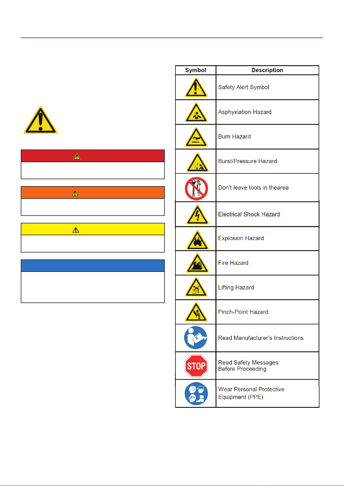
DANGER
;OPZTHU\HSJVU[HPUZPTWVY[HU[PUZ[Y\J[PVUZMVYVWLYH[PUN[OPZNLULYH[VY-VY`V\YZHML[`HUK[OLZHML[`VMV[OLYZILZ\YL
[VYLHK[OPZTHU\HS[OVYV\NOS`ILMVYLVWLYH[PUN[OLNLULYH[VY-HPS\YL[VWYVWLYS`MVSSV^HSSPUZ[Y\J[PVUZHUKWYLJH\[PVUZ
JHUJH\ZL`V\HUKV[OLYZ[VILZLYPV\ZS`O\Y[VYRPSSLK
"
#"
#"
$ %&
! '
(
)*!(
+
,-!+
) *+
. /
/
$*/
01/
-,2
*-12
*1!34
,5!!34
,5134
$!33
,.-$33
*36
! 3"
*3"
753"
1%3"
3&
3&
513'
,513'
513'
,513(
!3(
,!3(
#!)3+
-3+
, 3/
,89.3/
,*32
) 32
64
63
WARRANTY ........................................................................................................................................................................................................................................................................ 22

SAFETY DEFINITIONS
The words DANGER, WARNING, CAUTION and
NOTICE are used throughout this manual to highlight
important information. Be certain that the meanings of
these alerts are known to all who work on or near the
equipment.
This safety alert symbol appears
with most safety statements. It
means attention, become alert, your
safety is involved! Please read and
abide by the message that follows
the safety alerts symbol.
DANGER
Indicates a hazardous situation which, if not
avoided, will result in death or serious injury.
WARNING
Indicates a hazardous situation which, if not
avoided, could result in death or serious injury.
CAUTION
Indicates a hazardous situation which, if not
avoided, could result in minor or moderate injury.
NOTICE
Indicates a situation which can cause damage
to the generator, personal property and/or the
environment, or cause the equipment to operate
improperly.
NOTE: Indicates a procedure, practice or condition
that should be followed in order for the
generator to function in the manner
intended.
SAFETY
SAFETY SYMBOL DEFINITIONS

DANGER
Never use the inverter in a location that is wet or damp. Never expose the inverter to rain, snow,
water spray or standing water while in use. Protect the inverter from all hazardous weather
conditions. Moisture or ice can cause a short circuit or other malfunction in the electrical circuit.
Never operate the inverter in an enclosed area. Engine exhaust contains carbon monoxide. Only
operate the inverter outside and away from windows, doors and vents.
WARNING
Voltage produced by the inverter could result in death or serious injury.
• Never operate the inverter in rain or a ood plain unless proper precautions are taken to avoid
being subject to rain or a ood.
• Never use worn or damaged extension cords.
• Always have a licensed electrician connect the inverter to the utility circuit.
• Never touch an operating inverter if the inverter is wet or if you have wet hands.
•Never operate the inverter in highly conductive areas such as around metal decking or steel works.
• Always use grounded extension cords. Always use three-wire or double-insulated power tools.
• Never touch live terminals or bare wires while the inverter is operating.
• Be sure the inverter is properly grounded before operating.
WARNING
Gasoline and gasoline vapors are extremely ammable and explosive under certain conditions.
• Always refuel the generator outdoors, in a well-ventilated area.
• Never remove the fuel cap with the engine running.
• Never refuel the inverter while the engine is running. Always turn engine o and allow the
generator to cool before refueling.
• Only ll fuel tank with gasoline.
• Keep sparks, open ames or other form of ignition (such as match, cigarette, static electric
source) away when refueling.
• Never overll the fuel tank. Leave room for fuel to expand. Overlling the fuel tank can result in a
sudden overow of gasoline and result in spilled gasoline coming in contact with HOT surfaces.
Spilled fuel can ignite. If fuel is spilled on the inverter, wipe up any spills immediately. Dispose of
rag properly. Allow area of spilled fuel to dry before operating the inverter.
• Wear eye protection while refueling.
• Never use gasoline as a cleaning agent.
• Store any containers containing gasoline in a well-ventilated area, away from any combustibles or
source of ignition.
• Check for fuel leaks after refueling. Never operate the engine if a fuel leak is discovered.
WARNING
Never operate the inverter if powered items overheat,
electrical output drops, there is sparking, ames or smoke
coming from the inverter, or if the receptacles are damaged.
Never use the inverter to power medical support equipment.
Always remove any tools or other service equipment used
during maintenance from the inverter before operating.
NOTICE
Never modify the inverter.
Never operate the inverter if it
vibrates at high levels, if engine
speed changes greatly or if the
engine misres often.
Always disconnect tools or
appliances from the
inverter before starting.
GENERAL SAFETY RULES
SAFETY

When transporting or servicing the generator:
• Make certain the fuel shuto valve is o and the fuel
tank is empty.
• Make sure the LPG tank and LPG hose is not attached
to the generator.
• Disconnect the spark plug wire.
When storing the generator:
• Store away from sparks, open ames, pilot lights, heat
and other sources of ignition.
• Do not store gas or LPG tank near furnaces, water
heaters or any other appliances that produce heat or
have automatic ignitions.
CAUTION
Only use approved LPG tanks with OPD
(overlling prevention device) valve. Always
keep the tank in a vertical position with the
valve on top and installed at ground level
on a at surface. Do not allow tanks to be
around any heat source and make sure it is
not exposed to the sun, rain and dust. When
transporting and storing, turn o the tank
valve and fuel valve, and disconnect the tank.
Make sure to always cover the generator and
tank outlet with protective plastic caps.
Large (500-1000 gallon) LPG tanks will
require a certied plumber to install the fuel
line to the generator and the loose regulator
is not used (the regulator that is attached to
the fuel tank). The pressure as measured at
the regulator mounted to the generator must
be 7” to 14” of water column. The plumber
will ensure that the pressure is correct or
install a step down regulator if needed.
CAUTION
Do not allow children to tamper or play with
the propane tank or hose connections.
WARNING
If there is a strong smell of propane while
operating the generator close the valve on
the propane tank immediately. Once the
propane is o, use soapy water to check for
leaks on the hose and connections on the
tank valve and the generator. Do not smoke
or light a cigarette or check for leaks using
any open ame source such as a match or
lighter. If a leak is found contact a qualied
technician to inspect and repair the LPG
system before using the generator.
DANGER
Gasoline and liquid petroleum gas
(LPG) are highly explosive and
ammable. Explosions and re can
cause severe burns or death.
Gasoline and gasoline vapor (Gas)
• Gasoline is highly ammable and explosive.
• Gas expands and contracts with dierent
temperatures.
•
•
In case of a gas re, do not attempt to extinguish the
ame if the fuel shuto valve is in the on position.
Introducing an extinguisher to a generator with an
open fuel valve could create an explosion hazard.
Gas has a distinctive odor, this will help detect
potential leaks quickly.
• Gas vapors can cause a re if ignited.
•Gasoline is a skin irritant and needs to be cleaned up
immediately if it comes in contact with the skin.
Liquid Petroleum Gas (Propane/LPG)
• LPG/Propane is highly ammable and explosive.
• Flammable gas under pressure can cause a re or
explosion if ignited.
• LPG/Propane can settle in low places because it is
heavier than air.
• LPG/Propane has a distinctive odor added to help
detect potential leaks.
• Always keep LPG/Propane tank in an upright position.
• When exchanging LPG/Propane tanks, be sure the
tank value is the same type.
• In case of a LPG/Propane re, do not attempt to
extinguish unless the fuel supply can be shut o.
• LPG/Propane will burn the skin. Prevent skin contact
at all times.
WARNING
Never use a gas container, LPG
connector hose, LPG tank or any
other fuel item that appears to be
damaged.
When starting generator:
• Make sure that the gas cap, air lter, spark plug, fuel
lines and exhaust system are properly in place.
• If you spill any gasoline on the tank, allow it to fully
evaporate before operating.
•Make sure the generator and propane tank are on a
at surface before operating.
•If there is a propane odor do not start the unit because
there may be a potential leak.
• Never place propane tank near engine exhaust.
FUEL SAFETY
SAFETY

Control Panel: Contains the reset breaker,
outlets and warning lights.
Oil Access Cover: Remove the cover to
access the oil ll/drain plug.
Recoil Handle: Pull to manually start the
engine.
Fuel Cap: Close until clicking sound is heard.
Engine Service Panel: Remove the panel to
access the engine, air lter, spark plug and oat
bowl for maintenance.
Muer and Spark Arrestor: Avoid contact
until the engine is cooled down. The spark
arrestor prevents sparks from exiting the
muer. It must be removed for servicing.
FEATURES
BASIC INVERTER FEATURES
1
5
6
7
8
9
10
11
2
3
4
Roller Board Wheels: For easy portability.
Telescoping Handle: Extends and retracts for
easy access.
Carry Handles: Built in handles to allow for
easy pick up.
Battery Access Panel: Easy access to
battery.
Automatic Choke: Unit will automatically set
choke for electric and manual start (battery
must be hooked up, even if it is dead, for auto
choke to work with manual start)
2
3
6
7
9
10
4
5
11 8
1
SPECIFICATIONS
Model DLG4000iSE
AC
Output
Frequency 60Hz
Voltage 120V
Rated Power 3500W
Max. Power 3800W
DC Output 12V 8A
Engine DHLG225 224cc
Single cylinder, 4 Stroke, OHV, Air Cooled
Engine Oil 10W30 (0.6L)
Fuel Unleaded Gasoline/Propane

CONTROL PANEL FEATURES
BEFORE STARTING THE INVERTER
Location Selection – Before starting the inverter, avoid
exhaust and location hazards by verifying:
• You have selected a location to operate the inverter
that is outdoors and well ventilated.
• You have selected a location with a level and solid
surface on which to place the inverter.
• You have selected a location that is at least 6 feet
(1.8 m) away from any building, other equipment or
combustible material.
• If the inverter is located close to a building, make
sure it is not located near any windows, doors and/
or vents.
WARNING
Always operate the inverter on a level
surface. Placing the inverter on non
level surfaces can cause the inverter
to tip over, causing fuel and oil to spill.
Spilled fuel can ignite if it comes in
contact with an ignition source such
as a very hot surface.
NOTICE
Only operate the inverter on a solid, level surface.
Operating the inverter on a surface with loose
material such as sand or grass clippings can cause
debris to be ingested by the inverter that could:
• Block cooling vents
• Block air intake system
Receptacles
These can be used for operating appropriate
appliance, electrical lighting, tools, and motor
loads.
Choke lever: Control the choke on and off.
Output Ready LED: Indicates the inverter is
ready to be used.
Overload LED: Indicates that the inverter is
overloaded.
Low Oil LED: Indicates low oil level.
Fuel Selector Switch: Select and turn on gas
or propane. You can’t switch fuel sources
while unit is running.
Push Switch Automated Start: Push the
switch to “start” to start the engine. Push the
switch to “stop” to the engine.
Efficiency Mode Switch: When turned to the ON
position, the engine will sense the load needed and
run at a slower RPM to save fuel.
DC Receptacle
The DC receptacle should ONLY be used for
charging 12 Volt automotive type batteries.
Propane Hook Up: Hook up your propane tank
with the LPG hose provided to this inlet.
Parallel outlets
Parallel outlets enable a user to run two
generators simultaneously.
Ground Terminal:
The ground terminal is used to externally ground
the inverter.
1
2
3
4
5
6
7
8
9
11
12
10
BEFORE STARTING THE INVERTER,
REVIEW SAFETY SECTION STARTING
ON PAGE 3.
OPERATION
①
③④⑤
⑥
⑦
⑧
⑨
⑪
⑫
②
⑩
①
③④⑤
⑥
⑦
⑧
⑨
⑪
⑫
②
⑩

Weather – Never operate your inverter outdoors during
rain, snow or any combination of weather conditions that
could lead to moisture collecting on, in or around the
generator.
Dry Surface – Always operate the inverter on a dry
surface free of any moisture.
No Connected Loads – Make sure the inverter has no
connected loads before starting it. To ensure there are no
connected loads, unplug any electrical extension cords
that are plugged into the control panel receptacles.
NOTICE
Starting the inverter with loads already applied to
it could result in damage to any appliance being
powered o the inverter during the brief start-up
period.
WARNING
Be sure the inverter is properly
connected to earth ground before
operating.
High Altitude Operation
Engine power is reduced the higher you operate above
sea level. Output will be reduced approximately 3.5% for
every 1000ft of increased altitude from sea level. This is
a natural occurrence and cannot be adjusted by engine.
Increased exhaust emissions can also result due to
increased fuel mixture. Other issues include hard starting,
increased fuel consumption and spark plug fouling.
WARNING
Do not rest inverter on exhaust panel.
Do not move Generator while it is
on. The inverter will be damaged if
operated in this manner.
OPERATION
Grounding
Consult with your local municipalities for your
grounding codes.
Ground Terminal
Generator must be
properly grounded to
prevent electrocution.

POWERCORD
Using Extension Cords
Westinghouse Portable Power assumes no responsibility for the content within this table. The use of this table is the
responsibility of the user only. This table is intended for reference only. The results produced by using this table are
not guaranteed to be correct or applicable in all situations as the type and construction of cords are highly variable.
Always check with local regulations and a licensed electrician prior to installing or connecting an electrical appliance
INVERTER PARALLELING OPERATION
DANGER
Never connect the paralleling cord
to the inverters with the inverters
running. The inverters must not be
running and both the paralleling cord
switches must be o when connecting
the cords.
WARNING
Do not attempt to parallel the inverter
with any other manufacturers’
inverters. Do not use the paralleling
cord for any application other than
inverter paralleling. Do not use this
cord on other manufacturers’
inverters.
Always ensure that both ends of
the paralleling cord are switched o
before connecting the inverters.
OPERATION
INVERTER PARALLELING OPERATION
Maximum Power in Parallel Operation:
Rated Power in Parallel Operation:
Note:

INITIAL OIL FILL
BEFORE ADDING ENGINE OIL, REVIEW
SAFETY SECTION STARTING ON PAGE .
NOTICE
Engine oil must be added when the inverter is on a
at, level surface, or an inaccurate reading may result.
Do not overll. If the engine is overlled with oil, it can
cause serious engine damage.
1. Unclip and remove the oil service panel to access
the oil ll/drain plug (see Figure 3).
Figure 3: Oil Service Panel
2. Clean area around oil ll/drain plug and remove
plug.
3. Using the supplied funnel and oil, pour the entire
bottle of oil into the engine. See correct oil level in
Figure 4 below.
Figure 4: Engine Oil Correct Level
4. Do not overll, if oil level is too high, oil will drain
out through the ll plug.
OPERATION
ADDING/CHECKING ENGINE
FLUIDS AND FUEL
BEFORE ADDING/CHECKING ENGINE
FLUIDS AND FUEL, REVIEW SAFETY
SECTION STARTING ON PAGE .
DANGER
Filling the fuel tank with gasoline while
the inverter is running can cause
gasoline to leak and come in contact
with hot surfaces that can ignite the
gasoline.
Before starting the inverter, always check the level of:
•Engine oil
•Gasoline in the fuel tank
Once the inverter is started and the engine gets warm,
it is not safe to add gasoline to the fuel tank or engine
oil to the engine while the engine is running or the en-
gine and muer are hot.
CHECKING AND / OR ADDING ENGINE OIL
WARNING
Internal pressure can build in the
engine crankcase while the engine
is running. Removing the oil ll plug/
dipstick while the engine is hot can
cause extremely hot oil to spray out of
the crankcase and can severely
burn skin. Allow engine oil to cool for
several minutes before removing the
oil ll plug/dipstick.
The unit as shipped does not contain oil in the engine.
You must add engine oil before starting the inverter
for the rst time. See Initial Oil Fill for instructions on
checking engine oil level and the procedure for adding
engine oil.
NOTICE
The engine does not contain engine oil as shipped.
Attempting to start the engine without adding
engine oil will permanently damage internal engine
components.
The engine is equipped with a low oil shutdown
switch. If the oil level becomes low, the engine may
shut down and not start until the oil is lled to the
proper level.
The owner of the inverter is responsible to ensure the
proper oil level is maintained during the operation of
the generator. Failure to maintain the proper oil level
can result in engine damage.
1

ADDING GASOLINE TO THE FUEL TANK
WARNING
Never refuel the inverter while the
engine is running.
Always turn the engine o and allow
the inverter to cool before refueling.
CAUTION
Avoid prolonged skin contact with
gasoline. Avoid prolonged breathing of
gasoline vapors.
Required Gasoline – Only use gasoline that meets the
following requirements:
• Unleaded gasoline only
• Gasoline with maximum 10% ethanol added
•Gasoline with an 87 octane rating or higher
Filling the Fuel Tank – Follow the steps below to ll the
fuel tank:
1. Shut o the inverter.
2. Allow the inverter to cool down so all surface areas
of the muer and engine are cool to the touch.
3. Move the inverter to a at surface.
4. Clean area around the fuel cap.
5. Remove the fuel cap by rotating counterclockwise.
NOTICE
Do not overll the fuel tank. Spilled fuel will damage
some plastic parts.
6. Slowly add gasoline into the fuel tank. Be very care-
ful not to overll the tank. The gasoline level should
NOT be higher than the red ring (see Figure 5).
7. Install the fuel cap by rotating clockwise.
Figure 5: Maximum Gasoline Fill Level
OPERATION
11
CONNECTING THE LPG/PROPANE TANK
BEFORE CONNECTING PROPANE TANK
TO THE GENERATOR PLEASE REVIEW
FUEL SAFETY SECTION ON PAGE
Connecting LPG Tank
1. Make sure the inverter is o, on a at surface in well
ventilated area.
2. Make sure propane tank valve is in the o position.
3. Make sure the fuel selector switch on the inverter
control panel is pointing downward to “Propane”.
4. Remove the plastic cover on the generator propane
inlet valve.
5. Using your ngers tighten the LPG hose (included)
end below to the generator propane inlet. DO NOT
OVER-TIGHTEN 35-88 Ib-in maximum.
6. Attach the other end of the hose to a tank of LPG/
Propane and hand tighten.
7. Check all connections for leaks by wetting the
ttings with soapy water. Anywhere that bubbles
appear or grow indicates a leak in the connection.
If a leak exists at a tting then turn o the tank
valve and tighten the tting. Turn the gas back on
and recheck with soapy water again. If the leak
continues or if the leak is not at a tting then do not
use the generator and contact customer service.
NOTICE
• The LPG tank can be of any capacity but the tank must conform
to the standard as previously listed in Fuel Safety section.
• LPG tanks that use liquid withdrawal system can not be used on
these models.
• Verify the requalication date on the tank has not expired.
• All new tanks must be purged of air and moisture prior to lling.
Used tanks that have not been plugged or kept closed must also
be purged
• The purging process should be done by a LPG supplier. (Tanks
from an exchange supplier should have been purged and lled
properly already)
• Always position the tank so the connection between the valve
and the gas inlet won’t cause sharp bends or kinks in the hose.
WARNING
Do not start generator if you smell propane.
This may result in explosion hazard. Do not use
provided LPG hose for any other appliances.
Always turn o the propane tank and
disconnect LPG hose when not in use.

OPERATION
12
STARTING THE INVERTER
BEFORE STARTING THE INVERTER,
REVIEW SAFETY SECTION
STARTING ON PAGE .
For proper starting and operation of the inverter,
make sure you review the inverter features and their
descriptions in Features section.
Before attempting to start the inverter, verify the
following:
• The engine is lled with engine oil (see Figure 4:
Engine Oil Correct Level).
• The inverter is situated in a proper location (see
Location Selection).
• The inverter is on a dry surface (see Weather and Dry
Surface).
• All loads are disconnected from the inverter (see No
Connected Loads).
• The inverter is properly grounded (see Grounding the
Inverter)
DANGER
Never use the inverter in a location that is wet or
damp. Never expose the inverter to rain, snow,
water spray or standing water while in use. Protect
the inverter from all hazardous weather conditions.
Moisture or ice can cause a short circuit or other
malfunction in the electrical circuit.
Never operate the inverter in an enclosed area.
Engine exhaust contains carbon monoxide.
Only operate the inverter outside and away from
windows, doors and vents.
1. Check oil levels (see Initial Oil Fill)
2. Make sure nothing is plugged into any of the
outlets.
3. Make sure battery is connected (see Hooking Up
the Battery).
4. Make sure the circuit breakers are properly set
(see Figure 6).
12
5. Select fuel source for start up:
FOR GASOLINE
a. Make sure there is gas in the tank (see Adding
Gasoline to the Fuel Tank).
b. Turn fuel selector knob to GASOLINE (see
Figure 7).
Figure 7: Turn Fuel selector to GAS position
FOR LPG/PROPANE:
a. Make sure the LPG hose is safely secured from
the generator to the tank (see Connecting the
LPG Tank).
b. Turn the fuel selector knob to PROPANE (see
Figure 8).
c. Fully open the valve on the propane tank.
Figure 8: Turn fuel selector to PROPANE position
Propane tank valve - OPEN
. Choose starting method:
a. Recoil Start: irmly
grasp and pull the recoil handle slowly until you
feel increased resistance. At this point, apply a
rapid pull while pulling up and slightly away
from the generator.
.
b. Start:
START.
.
1
2
Figure 6: Breakers
120V Circuit Breaker Operating Position
120V Circuit Breaker Tripped Position

OPERATION
1
USING EFFICIENCY MODE
The inverter is equipped with an eciency mode switch
to minimize fuel consumption. In eciency mode, the
inverter will sense the load and adjust the engine RPM
to the current load requirements. Eciency mode
should be used only after the inverter has been warmed
up to operating temperature.
1. To turn on the eciency mode, press the switch to
the ON position).
2. If no load is present, the inverter RPM will drop
down to an idle speed.
3. As a load is applied, the inverter will sense the load
and engine RPM will increase according to the load
applied.
4. To run the inverter at maximum power and RPM,
press the eciency mode switch to the OFF
position.
OVERLOAD RESET
An electrical overload or short circuit will trip the
overload protection system by disconnecting the
generator’s AC output even though the engine is still
running. If this occurs, the overload alarm light will be
illuminated red and the output indicator light will be o.
The AC output can be restored as follows:
1. Turn off and unplug any electrical devices or
cords from the 120-Volt AC receptacle on the
control panel.
2. Press the generator reset button on the control
panel until the overload alarm light goes o and the
output indicator light is illuminated green.
3. Check that the intended electrical running and
starting loads do not exceed the generator’s
capacity or have a licensed electrician rectify any
fault causing a short circuit in the load.
4. Reconnect any electrical devices or cords to the
receptacles on the control panel and then turn on
the electrical loads as required.
SWITCHING FUEL SOURCES
PLEASE REVIEW FUEL SAFETY
SECTION ON PAGE
The below assumes that the propane fuel line is already
attached to the generator securely and safely.
While the unit is running simply turn the FUEL
SELECTOR knob to the desired fuel source. If you
want to switch from gasoline to propane make sure the
propane tank valve is open before you switch. When
you move from propane to gasoline shut the propane
valve after you have switched to gas.
NOTICE
If you do not plan on operating the unit on propane do not leave
the propane tank valve open.
When starting on propane the engine may run rough for a few
seconds while it purges gasoline in the carburetor.
If the engine fails when switching fuel sources simply restart the
unit on the fuel source that you switched to.
STOPPING THE INVERTER
Normal Operation
During normal operation, use the following steps to
stop your inverter:
1. Remove any connected loads from the control
panel receptacles.
2. Allow the inverter to run at “no load” to reduce and
stabilize engine and alternator temperatures.
3. Press and hold the Push Start/ utton
23second.see Figure 9).
4. .
Figure 9: Stopping generator

CAUTION
Avoid skin contact with engine oil or
gasoline. Prolonged skin contact with
engine oil or gasoline can be harmful.
Frequent and prolonged contact with
engine oil may cause skin cancer.
Take protective measures and wear
protective clothing and equipment.
Wash all exposed skin with soap and
water.
WARNING
Failure to perform periodic
maintenance or not following
maintenance procedures can cause
the inverter to malfunction and could
result in death or serious injury.
NOTICE
Periodic maintenance intervals vary depending on
inverter operating conditions. Operating the inverter
under severe conditions, such as sustained high-
load, high-temperature, or unusually wet or dusty
environments, will require more frequent periodic
maintenance. The intervals listed in the maintenance
schedule should be treated only as a general
guideline.
WARNING
Avoid accidentally starting the inverter
during maintenance by removing
the spark plug boot from the spark
plug. For electric start inverters, also
disconnect the battery cables from the
battery (disconnect the black negative
(-) cable rst) and place the cables
away from the battery posts to avoid
arcing.
Allow hot components to cool to
the touch prior to performing any
maintenance procedure.
Internal pressure can build in the
engine crankcase while the engine
is running. Removing the oil ll plug/
dipstick while the engine is hot can
cause extremely hot oil to spray out
of the crankcase and can severely
burn skin. Allow engine oil to cool for
several minutes before removing the
oil ll plug/dipstick.
Always perform maintenance in a well-
ventilated area. Gasoline fuel and fuel
vapors are extremely ammable and
can ignite under certain conditions.
MAINTENANCE
BEFORE PERFORMING MAINTENANCE ON THE INVERTER, REVIEW
THE SAFETY SECTION STARTING ON PAGE , AS WELL AS THE
FOLLOWING SAFETY MESSAGES.
TABLE 1: MAINTENANCE SCHEDULE - OWNER PERFORMED
Maintenance Item
Before Every
Use
After First 20
Hours or First
Month of Use
After 50 Hours
of Use or Every
6 Months
After 100 Hour
of Use or Every
6 Months
After 300 Hours
of Use or Every
Year
Engine Oil Check Level Change Change - -
Cooling Features Check/Clean - - - -
Air Filter Check -Clean* - Replace
Spark Plug - - - Check/Clean Replace
Spark Arrestor - - - Check/Clean -
*Service more frequently if operating in dry and dusty conditions
Following the maintenance schedule is important to keep the inverter in good operating condition. The following is a
summary of maintenance items by periodic maintenance intervals.
1

NOTICE
Engine oil must always be checked and added when
the inverter is on a at, level surface, or an inaccurate
reading may result, causing serious engine damage.
ADDING ENGINE OIL
1. Always operate or maintain the inverter on a at
surface.
2. Stop engine if running.
3. Let engine sit and cool for several minutes (allow
crankcase pressure to equalize).
4. Remove the engine service panel to gain access to
the oil ll/drain plug.
5. Thoroughly clean around the oil ll/drain plug.
6. Remove the oil ll/drain plug.
7.
8.
Select the proper engine oil as specified in Figure 1.
Using the supplied oil funnel, slowly add engine oil
to the engine. Stop frequently to check the oil level
and avoid overfilling.
CHANGING ENGINE OIL
1. Stop the engine.
2. Let engine sit and cool for several minutes (allow
crankcase pressure to equalize).
3. Remove the oil service panel to gain access to the
oil ll/drain plug.
4. Place oil pan (or suitable container) under the oil ll/
drain plug.
5. Remove oil ll/drain plug. With a damp rag, thor-
oughly clean around the oil ll/drain plug.
6. Insert provided funnel around oil ll/drain and
carefully tilt the inverter so the oil drains down the
through the funnel into the container.
7. Allow oil to completely drain.
8. Fill crankcase with oil following the steps outlined in
Adding Engine Oil above and tighten oil plug.
9. Dispose of used engine oil properly.
NOTICE
Never dispose of used engine oil by dumping the
oil into a sewer, on the ground, or into groundwater
or waterways. Always be environmentally
responsible. Follow the guidelines of the
governmental agencies for proper disposal of
hazardous materials. Consult local authorities or
reclamation facility.
ENGINE OIL MAINTENANCE
Engine Oil Specication
1. Only use the engine oil specified in Figure 1.
2. Only use 4-stroke/cycle engine oil. NEVER USE
2-STROKE/CYCLE OIL. Synthetic oil is an
acceptable substitute for conventional oil.
NOTICE
Always maintain proper engine oil level. Failure to
maintain proper engine oil level could result in severe
damage to the engine and/or shorten the life of the
engine.
Always use the specied engine oil. Failure to use the
specied engine oil can cause accelerated wear and/
or shorten the life of the engine.
Engine oil level should be checked before every use.
1. Always operate or maintain the inverter on a flat
surface.
2. Stop engine if running.
3. Let engine sit and cool for several minutes (allow
crankcase pressure to equalize).
4. Remove the oil service panel to access the oil fill/
drain plug (see Figure 3 on page 1).
. With a damp rag, clean around the oil fill/drain plug.
. Remove the oil fill/drain plug.
7. Check oil level: When checking the engine oil, remove
the oil fill/ drain plug (see Figure 4 on page 1).
• The oil level is acceptable if oil is visible at the
bottom of the threads of the oil ll plug.
• If oil level is low, add to the correct level using
the supplied oil ll bottle. Do not overll the oil
crankcase.
MAINTENANCE
1
Figure 10: Recommended Oil
CHECKING ENGINE OIL

4. Remove the foam element from the air cleaner
housing.
5. Wash the foam air lter element by submerging
the element in a solution of household detergent
soap and warm water. Slowly squeeze the foam to
thoroughly clean.
NOTICE
NEVER twist or tear the foam air lter element
during cleaning or drying. Only apply slow but rm
squeezing action.
6. Rinse in clean water by submerging the air lter el-
ement in fresh water and applying a slow squeezing
action (see Figure 13).
Figure 1: Squeeze Air Filter
NOTICE
Never dispose of soap cleaning solution used to
clean the air lter by dumping the solution into
a sewer, on the ground, or into ground water or
waterways. Always be environmentally responsible.
Follow the guidelines of the governmental
agencies for proper disposal of hazardous
materials. Consult local authorities or reclamation
facility.
7. Dispose of used soap cleaning solution properly.
8. Dry the air lter element by again applying a slow
rm squeezing action.
9. Return the air lter element to its position in the air
cleaner housing.
10. Install the air cleaner cover, making sure the knobs
lock into place.
11. Install the engine service panel.
AIR FILTER MAINTENANCE
WARNING
Never use gasoline or other ammable
solvents to clean the air lter. Use only
household detergent soap to clean the
air lter.
Cleaning the Air Filter
The air lter must be cleaned after every 50 hours of
use or 3 months (frequency should be increased if
inverter is operated in a dusty environment).
1. Turn off the inverter and let it cool for several min-
utes if running.
2. Remove the Engine Service Panel to gain access to
the air filter (see Figure 11).
Figure 1 Remove Engine Service Panel
3. Turn the 2 knobs on the air cleaner to unlock the
cover. Tip the cover down to access the foam ele-
ment (see Figure 12).
MAINTENANCE
Figure 1: Unlock Air Filter Cover
1

SPARK PLUG MAINTENANCE
The spark plug must be checked and cleaned after ev-
ery 100 hours of use or 6 months and must be replaced
after 300 hours of use or every year.
1. Stop the inverter and let it cool for several minutes if
running.
2. Move the inverter to a flat, level surface.
3. Remove the Engine Service Panel to gain access to
the spark plug (see Figure 11 on page 1).
4. Remove the spark plug cover by firmly pulling the
metal spark plug boot handle directly away from the
engine (see Figure 1).
Figure 1: Pull o Spark Plug Cover
NOTICE
Never apply any side load or move the spark plug
laterally when removing the spark plug. Applying a
side load or moving the spark plug laterally may crack
and damage the spark plug boot.
. Clean area around the spark plug.
. Using the spark plug socket wrench provided,
remove the spark plug from the cylinder head (see
Figure 17).
Figure 1: Remove Spark Plug
DRAINING THE FLOAT BOWL
1. Remove the Engine Service Panel to access the
carburetor (see Figure 11 on page 1).
2. Locate the clear plastic hose from the float that is
extending towards the bottom of the inverter, pull
those hose outside the body and place a suitable
container under it to catch the drained fuel (see
Figure 14).
Figure 1: Fuel Drain Hose
3. Loosen the oat bowl drain screw until fuel is seen
draining from the float bowl (see Figure 1).
Figure 1: Loosen Float Bowl Screw
4. Allow fuel to drain into the container, and then
tighten the oat bowl drain screw.
NOTICE
Never dispose of fuel by dumping fuel into a sewer, on the ground,
or into groundwater or waterways. Always be environmentally
responsible. Follow the guidelines of the EPA or other
governmental agencies for proper disposal of hazardous materials.
Consult local authorities or reclamation facility.
5. Install the engine service panel.
MAINTENANCE
fuel pan
fuel pan
1

Spark Plug Maintenance - Continued from page 18
7. Place a clean rag over the opening created by the
removal of the spark plug to make sure no dirt can
get into the combustion chamber.
8. Inspect the spark plug for:
• Cracked or chipped insulator
• Excessive wear
• Spark plug gap of 0.032 in. (0.80 mm).
If the spark plug fails any one of the
conditions listed above, replace the plug.
NOTICE
Only use the recommended spark plug. See chart
below. Using a non- recommended spark plug could
result in damage to the engine.
9. Install the spark plug by carefully following the
steps outlined below:
a. Carefully insert the spark plug back into the
cylinder head. Hand-thread the spark plug until
it bottoms out.
b. Using the spark plug socket wrench provided,
turn the spark plug to ensure it is fully seated.
c. Replace the spark plug boot, making sure the
boot fully engages the spark plug’s tip.
d. Install the spark plug access cover.
Recommended Spark Plug Replacement:
Torch Spark
plug
Champion Bosch Autolite
F7RTC N9YC W7DC 52
CLEANING THE SPARK ARRESTOR
Check and clean the spark arrestor after every 100
hours of use or 6 months.
1. Stop the inverter and let it cool for several minutes
if running.
2. Move the inverter to a flat, level surface.
3. Remove the screws holding the muffler cover in
place (see Figure 1).
4. Loosen the clamp holding the spark arrestor onto
the muffler.
. Slide the spark arrestor band clamp off the spark
arrestor screen.
6. Pull the spark arrestor screen o the muer
exhaust pipe.
7. Using a wire brush, remove any dirt and debris that
may have collected on the spark arrestor screen.
8. If the spark arrestor screen shows signs of wear
(rips, tears or large openings in the screen), replace
the spark arrestor screen.
9. Install the spark arrestor components in the
following order:
a. Place spark arrestor screen over the muer
exhaust pipe. Push on the screen until it fully
bottoms out.
b. Place the spark arrestor band clamp over the
screen and tighten with a athead screwdriver
10. Replace the discharge gate.
CHECKING AND ADJUSTING VALVE LASH
CAUTION
Checking and adjusting valve lash
must be done when the engine is cold.
1. Remove the rocker arm cover and carefully remove
the gasket. If the gasket is torn or damaged, it must
be replaced.
2. Remove the spark plug so the engine can be
rotated more easily.
3. Rotate the engine to top dead center (TDC) of the
compression stroke. Looking through the spark
plug hole, the piston should be at the top.
SPARK PLUG GAP
MAINTENANCE
Figure 18: Remove Muler Access Panel
1

4. Both the rocker arms should be loose at TDC on
the compression stroke. If they are not, rotate the
engine 360°.
. Insert a feeler gauge between the rocker arm and
the push rod and check for clearance (see Figure
1). See table below for valve lash specifications
Figure 19
(1) Push Rod, (2) Feeler Gauge Area
(3) Rocker Arm, (4) Jam Nut, (5) Adjusting Nut
Standard Valve Lash
Intake Valve Exhaust Valve
Valve Lash 0.0035 ± 0.0043 in
(0.09 ± 0.11 mm)
0.0043 ± 0.0051 in
(0.11 ± 0.13 mm)
Bolt Torque 8-12N.m 8-12N.m
6. If an adjustment is required, hold the adjusting nut
and loosen the jam nut.
7. Turn the adjusting nut to obtain the correct valve
lash. When the valve lash is correct, hold the ad-
justing nut and tighten the jam nut to 106 in-lb (12
N•m).
8. Recheck the valve lash after tightening the jam nut.
9. Perform this procedure for both the intake and
exhaust valves.
10. Install the rocker arm cover, gasket and spark plug.
CLEANING THE INVERTER
It is important to inspect and clean the inverter before
every use.
Clean All Engine Air Inlet and Outlet Ports – Make
sure all engine air inlet and outlet ports are clean of any
dirt and debris to ensure the engine does not run hot.
MAINTENANCE
12
3
4
5
BATTERY SERVICE
To ensure the battery remains charged, the generator
should be started every 2 to 3 months and run for a
minimum of 15 minutes or a charger should be plugged
into the generator and the generator should be charged
overnight. Plug the cord from the charger into the
charging port “ ” on the generator. Plug the charger
into a 220-volt AC outlet.
Battery Replacement
1. Remove the spark plug wire from spark plug.
2. Loosen the rubber strap holding the battery in
place.
3. Disconnect the black negative (-) battery cable from
the battery rst.
4. Disconnect the red positive (+) battery cable
second and remove the battery.
NOTICE
Dispose of the used battery properly according to
the guidelines established by your local or state
government.
5. Install the new battery into the generator frame.
6. Connect the red positive (+) battery cable to the
battery rst.
7. Connect the black negative (-) battery cable to the
battery second.
8. Replace rubber strap to hold battery in place.
9. Install the spark plug wire onto spark plug.
See below for the battery specication
when replacing the battery.
After Market Battery
Model
YT5AL
Volts 12
Amp Hr 5
Dimensions 4.63 in by 2.38 in by 5 in
1

5. Change the oil (see Changing Engine Oil on page
16).
6. Remove the spark plug (see Spark Plug
Maintenance on page 18) and place about 1
tablespoon of oil in the spark plug opening. While
placing a clean rag over the spark plug opening,
slowly pull the recoil handle to allow the engine to
turn over several times. This will distribute the oil
and protect the cylinder wall from corroding during
storage.
7. Replace the spark plug (see Spark Plug
Maintenance on page 18).
8. Move the inverter to a clean, dry place for storage.
STORAGE
WARNING
Never store an inverter with fuel in the
tank indoors or in a poorly ventilated
area where the fumes can come in
contact with an ignition source such
as a: 1) pilot light of a stove, water
heater, clothes dryer or any other gas
appliance; or 2) spark from an electric
appliance.
NOTICE
Gasoline stored for as little as 60 days can go bad,
causing gum, varnish and corrosive buildup in fuel
lines, fuel passages and the engine. This corrosive
buildup restricts the ow of fuel, preventing an engine
from starting after a prolonged storage period.
Proper care should be taken to prepare the inverter for
any storage
1. Clean the inverter.
2. Siphon all gasoline from the fuel tank as best as
possible.
3. Start the engine and allow the inverter to run until
all the remaining gasoline in the fuel lines and
carburetor is consumed and the engine shuts off.
4. Drain any remaining fuel from the float bowl. See
Draining the Float Bowl on page 17.
MAINTENANCE
2
Table of contents