Contents
Operator and Equipment Safety ............................................................................................................................................5
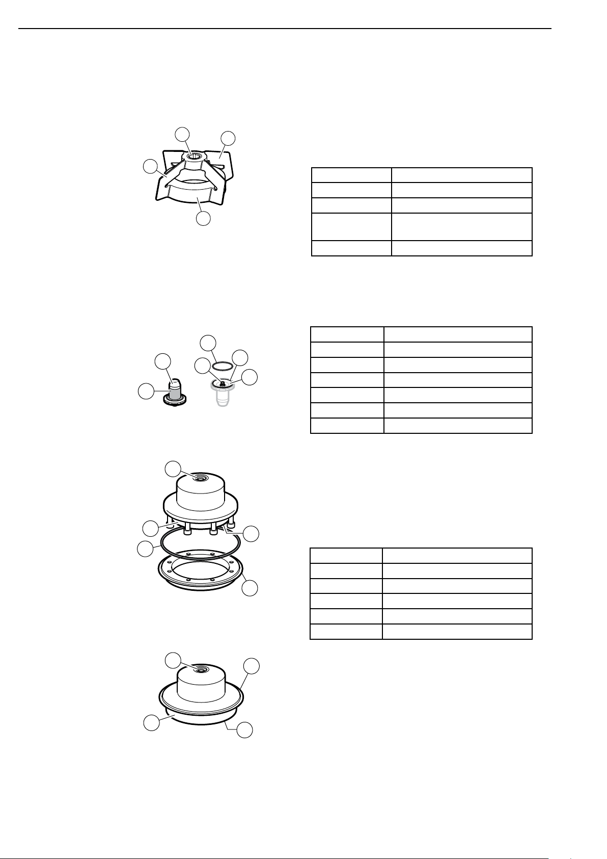
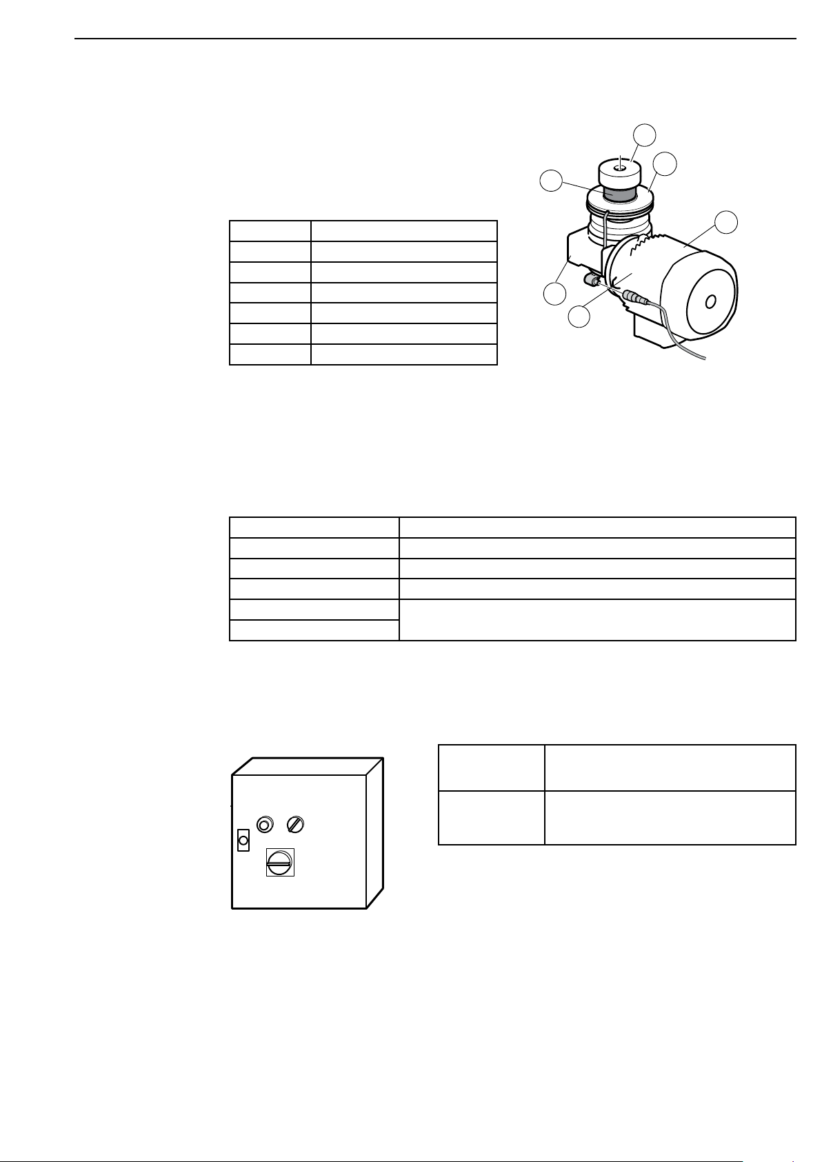
NovAseptic®GMP Mixer Components ..................................................................................................................................6
Required Tools..................................................................................................................................................................7
Additional Equipment....................................................................................................................................................7
Optional Equipment........................................................................................................................................................8
Installation and Operating Parameters................................................................................................................................9
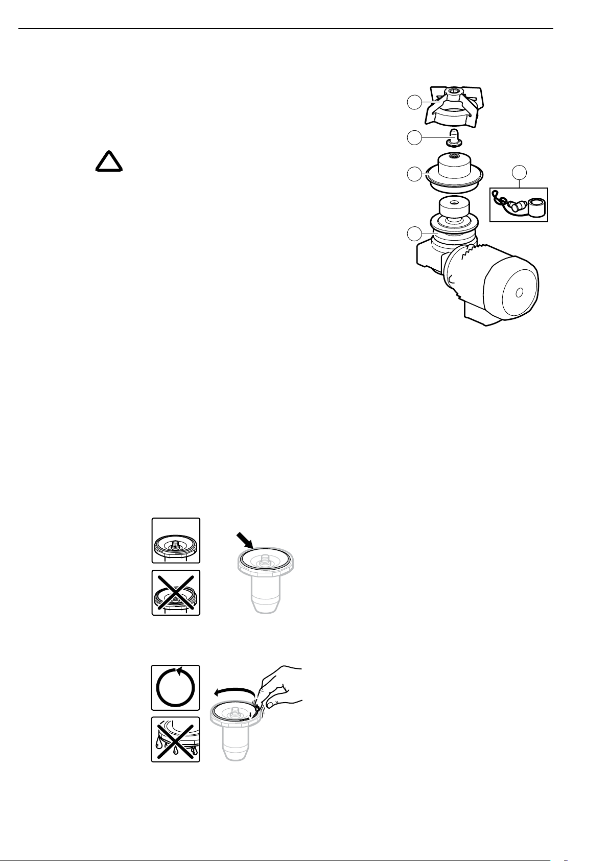
Installation................................................................................................................................................................................ 10
Male Bearing Installation.......................................................................................................................................... 10
Mixing Head Installation ........................................................................................................................................... 11
Drive Unit Installation ................................................................................................................................................ 12
Electrical Installation.................................................................................................................................................. 14
Operation................................................................................................................................................................................... 20
Starting the Mixer ....................................................................................................................................................... 20
Disassembly ................................................................................................................................................................... 21
Storage............................................................................................................................................................................ 21
Recycle and Disposal................................................................................................................................................... 21
Cleaning and Sterilizing Procedures.................................................................................................................................. 22
Cleaning in Place (CIP) ............................................................................................................................................... 22
Sterilizing in Place (SIP) ............................................................................................................................................. 22
Installation Checklist ............................................................................................................................................................. 24
Commissioning ........................................................................................................................................................................ 26
Valid Regulations ......................................................................................................................................................... 26
Installation Qualification Checklist ................................................................................................................................... 27
Installation Qualification ........................................................................................................................................ 27
Check Points.................................................................................................................................................................. 27
Maintenance Checklist.......................................................................................................................................................... 29
Spare Parts................................................................................................................................................................................ 30
Troubleshooting ....................................................................................................................................................................... 31
Standard Product Warranty ................................................................................................................................................. 33
Technical Assistance............................................................................................................................................................... 34
NovAseptic®GMP Mixer Installation and User Guide 3