manuals.online logo
Brands
  1. Home
  2. •
  3. Brands
  4. •
  5. M2 Antenna Systems
  6. •
  7. Antenna
  8. •
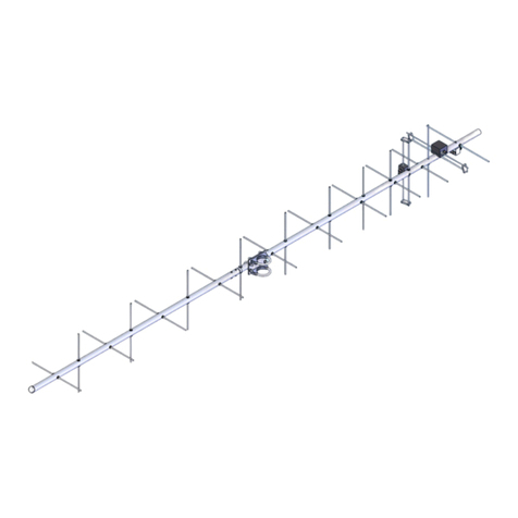
  9. M2 Antenna Systems 215-470LP16 User manual

M2 Antenna Systems 215-470LP16 User manual

M2 Antenna Systems, Inc. 4402 N. Selland Ave. Fresno, CA 93722
Tel: (559) 432-8873 Fax: (559) 432-3059 Web: www.m2inc.com
©2015 M2 Antenna Systems Incorporated 09/23/15
Rev.00
Model .........................................215-470LP16
Frequency Range.......................215-470 MHz Cont.
*Gain ..........................................8.5 dBi Typical Average
Front to back ..............................27 dB Typical Average
Beamwidth..................................@230MHz E=61°/H=92°
Beamwidth..................................@350MHz E=58°/H=89°
Beamwidth..................................@450MHZ E=59°/H=90°
Feed Impedance........................50 Ohms Unbalanced
Maximum VSWR........................>1.5:1 AVG.
Mounting Polarity........................Horizontal or Vertical
Mast............................................1.5-2.0 Dia
Input Connector..........................“N” Female
Power Handling..........................250 Watts
Boom Length / Dia......................42” / 3/4” SQ
Turning Radius:..........................21”
Wind area / Survival...................0.8 Sq. Ft. / 125 MPH
Weight / Ship Wt.........................14 lbs. / 16 lbs.
M2 Antenna Systems, Inc.
Model No: 215-470LP16
FEATURES:
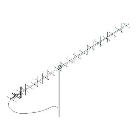
The 215-470LP16 is a dual boom log periodic with more elements than many conventional designs. The extra
elements help in lowering VSWR and produces higher gains across the working frequency range. The result is a high
quality commercial broad band VHF antenna. Built for extreme environmental conditions, this design uses 6061-t6 alumi-
num and all stainless hardware and UV stabilized acetyl insulation. Internal stainless screws secure the elements in
place. Optional models are available with welded elements for corrosive environments or extreme conditions. The 215-
470LP16 antenna can be ordered with many finishes, anodized, chem filmed, or a combination chem film and paint, with
many colors available.
SPECIFICATIONS:
*Subtract 2.14 from dBi for dBd
215-470LP16 DIMENSION SHEET
215-470LP16 HORIZONTAL MOUNTING
WITH HORIZONTAL
MOUNTING THE FEED
LINE CAN BE ATTACHED
TO THE LOWER BOOM
SECTION AND DOWN
THE MAST
WHEN ATTACHING
U-BOLT AND UNICRADLE
USE SIDE HOLES ON
MAST MOUNTING PLATE
HORIZONTAL MOUNTING
TO A VERTICAL MAST USING
THE SIDE MOUNT
OPTION
HORIZONTAL MOUNTING
TO A VERTICAL MAST USING
THE TOP MOUNT
OPTION
WHEN ATTACHING U-BOLTS
AND UNICRADLES
USE THE HOLES CENTERED
UNDER THE BOOM ON THE
MAST MOUNTING PLATE
215-470LP16 VERTICAL MOUNTING
NOTE THE POSITION OF THE
CONNECTOR MOUNTING
BRACKET, IT IS MOVED TO
THE REAR OF THE CABLE
ACCESS SLOT
WHEN CENTER MOUNTING ANTENNAS VERTICALLY POLARIZED IT
IS NESISARY TO MOUNT YOUR ANTENNAS ON A NON METALIC
MAST, AND FEED LINES NEED TO BE ROUTED OFF THE REAR OF
THE ANTENNA, BEHIND AND BELOW THE ELEMENTS AT LEAST 12”
FAILURE TO FOLLOW THIS PRACTICE CAN SEVELY DEGRADE THE
PERFORMANCE OF THE ANTENNA.
ATTACH THE FEED LINE
TO THE REAR BOOM
CABLE SUPPORT FOR
STRAN RELIEF OF THE
CABLE AND CONNECTOR.
NON METALLIC MAST
215-470LP16 ASSMBLY
1. Find the lower boom assembly with the cable access slot. Add the con-
nector mount bracket. Refer to the horizontal or vertical mounting options
pages to chose connector mount bracket location.
2. locate the Feedline RG-303 with connectors. Feed the SMA female con-
nector end of the cable inside the boom starting from the cable access
slot. Feed the cable thru past the front of the boom by 6”.
215-470LP16 ASSMBLY
3. Note the picture of the feed nose assembly, locate the grounded side of
the feed nose assembly. Warning The feed nose assembly when
unattached is fragile, after complete installation it will be very durable.
Care must be taken during the following steps.
4.Slide on the supplied 1/2 shrink tube onto the cable. Attach the feed
nose assembly to the end of the cable, slide the shrink tube over the mat-
ing SMA connectors and shrink.
GROUNDED
FEED NOSE
215-470LP16 ASSMBLY
5. Carefully slide the cable and feed nose assembly back into the boom
assembly, align the grounded side of the feed nose assembly with the
hole in the front of the boom assembly and add the 8-32 x 3/8 screw.
6. Add silicone sealant or equivalent around the feed nose and solder con-
nections as to seal for long term installation. Use appropriate topography
sealing techniques for long term installation.
5. Route the N connector thru the connector mount bracket, add lock
washer and nut and tighten.
215-470LP16 ASSMBLY
6. locate the front and rear delrin spreader bars. Add the both smaller front
spreader bars to either side of the boom assembly add the 8-32 screw
thru the boom and add the nut. Repeat for the rear end of the boom as-
sembly.
7. Find the upper boom section and attach to the open holes of the rear
spreader bars. Carefully bring the nose of the upper boom assembly clos-
er to the nose of the lower boom assembly, slide the center conductor side
of the feed nose assembly into the nose of the upper boom assembly and
add the 8-32 x 3/3 screw and tighten. Add the 8-32 screws to the front
spreader bars, add the nuts and tighten all the hardware.
215-470LP16 ASSMBLY
8. Locate the BTM side plate, BTM block and mast mount plate. See the
picture and assemble the BTM bracket. Add the u-bolts and
uni-cradles for your mounting style, horizontal or vertical polarity. Be sure
to tighten all hardware before installation. Always use good low loss coax
for feed line. Seal all exposed connectors with the appropriate sealing
techniques for your particular topography.
Screw, 8-32 x 1 3/4 ss
w/ lock nut
Screw, 8-32 x 1 1/2 ss
w/ lock nut
Screw, 1/4-20 x 1 3/4 ss
w/ lock nut
MAST MOUNT
PLATE
BTM SIDE
PLATE
BTM INSULATOR
PLATE
215-470LP16 PARTS & HARDWARE
DESCRIPTION...............................................................................QTY
BOOM ASSEMBLY W/ ELEMENTS, UPPER................................1
BOOM ASSEMBLY W/ ELEMENTS, LOWER...............................1
FEED NOSE ASSEMBLY ..............................................................1
FEED LINE, RG-303 W/ SMA FEMALE TO N FEMALE ...............1
CONNECTOR MOUNT BRACKET................................................1
REAR BOOM CABLE SUPPORT..................................................1
BTM SIDE PLATE..........................................................................2
BTM BLOCK...................................................................................1
MAST MOUNT PLATE...................................................................1
BTM INSULATOR PLATE2
FRONT SPREADER BAR, DELRIN2
REAR SPREADER BAR, DELRIN.................................................2
UNICRADLE, (M2AMC0076) .........................................................2
U-BOLT, 2” SS HINDLEY...............................................................2
PENETROX / ZINC PASTE CUP...................................................1
ASSEMBLY MANUAL....................................................................1
HARDWARE:
NUT,1/4-20 SS...............................................................................4
LOCKNUT, 1/4-20 SS ....................................................................2
LOCKWASHERS, 1/4 SS...............................................................4
BOLT,1/4-20X1/2,FH SCKT,SS .....................................................4
BOLT, 1/4-20X1-3/4” SS ................................................................2
SCREW, 8-32 X 1-3/4” SS .............................................................2
SCREW, 8-32 X 1-1/2 SS...............................................................6
SCREW, 8-32 X 1” SS....................................................................1
SCREW, 8-32 X 3/8” SS.................................................................4
LOCKWASER, #8 SS.....................................................................4
LOCKNUT, 8-32 SS .......................................................................9
CABLE TIE, 8” NYLON...................................................................4
SHRINK TUBE, 1/2 W/ SEALANT X 1 1/2”....................................1
ALLEN WRENCH, 5/32..................................................................1
M2ANTENNA SYSTEMS, INC.
4402 N. SELLAND AVE.
FRESNO, CA 93722
(559) 432-8873 FAX: 432-3059
www.m2inc.com Email: [email protected]

Other M2 Antenna Systems Antenna manuals

M2 Antenna Systems 8-30LP9 User manual

M2 Antenna Systems

M2 Antenna Systems 8-30LP9 User manual

M2 Antenna Systems 6M5XHG User manual

M2 Antenna Systems

M2 Antenna Systems 6M5XHG User manual

M2 Antenna Systems 40M3FS User manual

M2 Antenna Systems

M2 Antenna Systems 40M3FS User manual

M2 Antenna Systems 432-6WL User manual

M2 Antenna Systems

M2 Antenna Systems 432-6WL User manual

M2 Antenna Systems 393CP18 User manual

M2 Antenna Systems

M2 Antenna Systems 393CP18 User manual

M2 Antenna Systems 222 HO LOOP User manual

M2 Antenna Systems

M2 Antenna Systems 222 HO LOOP User manual

M2 Antenna Systems FGSD-2.4DH User manual

M2 Antenna Systems

M2 Antenna Systems FGSD-2.4DH User manual

M2 Antenna Systems 25M4 User manual

M2 Antenna Systems

M2 Antenna Systems 25M4 User manual

M2 Antenna Systems 303CP26 User manual

M2 Antenna Systems

M2 Antenna Systems 303CP26 User manual

M2 Antenna Systems Eggbeater EB-310 User manual

M2 Antenna Systems

M2 Antenna Systems Eggbeater EB-310 User manual

M2 Antenna Systems 418CP30 User manual

M2 Antenna Systems

M2 Antenna Systems 418CP30 User manual

M2 Antenna Systems 40M4LLDD User manual

M2 Antenna Systems

M2 Antenna Systems 40M4LLDD User manual

M2 Antenna Systems EB-432/RK70CM User manual

M2 Antenna Systems

M2 Antenna Systems EB-432/RK70CM User manual

M2 Antenna Systems 400CP30A User manual

M2 Antenna Systems

M2 Antenna Systems 400CP30A User manual

M2 Antenna Systems 248CP22A User manual

M2 Antenna Systems

M2 Antenna Systems 248CP22A User manual

M2 Antenna Systems 6M HO LOOP User manual
M2 Antenna Systems

M2 Antenna Systems 6M HO LOOP User manual

M2 Antenna Systems 222-10EZ User manual

M2 Antenna Systems

M2 Antenna Systems 222-10EZ User manual

M2 Antenna Systems 11M5DX User manual

M2 Antenna Systems

M2 Antenna Systems 11M5DX User manual

M2 Antenna Systems FD35.5 User manual

M2 Antenna Systems

M2 Antenna Systems FD35.5 User manual

M2 Antenna Systems 403CP20 User manual

M2 Antenna Systems

M2 Antenna Systems 403CP20 User manual

M2 Antenna Systems 249CP24 User manual

M2 Antenna Systems

M2 Antenna Systems 249CP24 User manual

M2 Antenna Systems 6M6LN User manual

M2 Antenna Systems

M2 Antenna Systems 6M6LN User manual

M2 Antenna Systems 348CP18 User manual

M2 Antenna Systems

M2 Antenna Systems 348CP18 User manual

M2 Antenna Systems 32 HO LOOP User manual

M2 Antenna Systems

M2 Antenna Systems 32 HO LOOP User manual

Popular Antenna manuals by other brands

STI-CO Dualband RDCA-DB-VHF/UHFL quick start guide

STI-CO

STI-CO Dualband RDCA-DB-VHF/UHFL quick start guide

Teleco VoyagerG3 65 Installation guide and user's manual

Teleco

Teleco VoyagerG3 65 Installation guide and user's manual

INAC MAK-721 PRO Instructions for fitting and use

INAC

INAC MAK-721 PRO Instructions for fitting and use

Parsec Antennas K9 installation instructions

Parsec Antennas

Parsec Antennas K9 installation instructions

Sennheiser AC 3 instruction manual

Sennheiser

Sennheiser AC 3 instruction manual

Altelix AS6G17B65M4-A5C Assembly instructions

Altelix

Altelix AS6G17B65M4-A5C Assembly instructions

TracStar MVS1200P4 Assembly instructions

TracStar

TracStar MVS1200P4 Assembly instructions

SMA EXTANT-US-40 installation manual

SMA

SMA EXTANT-US-40 installation manual

Patriot 75cm Offset Antenna Installation & assembly instructions

Patriot

Patriot 75cm Offset Antenna Installation & assembly instructions

Vislink ARTR manual

Vislink

Vislink ARTR manual

Ultra Start RFK4BAM installation guide

Ultra Start

Ultra Start RFK4BAM installation guide

MotoSAT DataStorm XF3 Brochure & specs

MotoSAT

MotoSAT DataStorm XF3 Brochure & specs

Feig Electronic OBID ID ANT.BS.100-A installation manual

Feig Electronic

Feig Electronic OBID ID ANT.BS.100-A installation manual

Winegard WX980 product manual

Winegard

Winegard WX980 product manual

THOMSON ANT1439 operating instructions

THOMSON

THOMSON ANT1439 operating instructions

Panorama Antennas CM-36-55 Series Installation instruction

Panorama Antennas

Panorama Antennas CM-36-55 Series Installation instruction

Elan EL-SC-ZW user guide

Elan

Elan EL-SC-ZW user guide

AvaLAN AW900XTP user manual

AvaLAN

AvaLAN AW900XTP user manual

manuals.online logo
manuals.online logoBrands
  • About & Mission
  • Contact us
  • Privacy Policy
  • Terms and Conditions

Copyright 2025 Manuals.Online. All Rights Reserved.