manuals.online logo
Brands
  1. Home
  2. •
  3. Brands
  4. •
  5. M2 Antenna Systems
  6. •
  7. Antenna
  8. •
  9. M2 Antenna Systems FGSD-3.7DH User manual

M2 Antenna Systems FGSD-3.7DH User manual

M2 ANTENNA SYSTEMS, INC. 4402 N. SELLAND AVE. FRESNO, CA 93722
TEL: (559) 432-8873 FAX: (559) 432-3059 WEB: WWW.M2INC.COM
©2020 M2 ANTENNA SYSTEMS INCOPORATED 6/24/2020
REV A
M2 ANTENNA SYSTEMS, INC.
DH SATELLITE DISH MOUNT
MODEL NO: FGSD-3.7DH
SATELLITE DISH MOUNT ASSEMBLY
STEP 1:
Mount one SATELLITE DISH SUP-
PORT to DISH MOUNT BASE PLATE. This
support will need to align with the holes in the
SATELLITE DISH, therefore leave the hard-
ware loose to allow for some adjustment during
assembly.
SATELLITE DISH SUPPORT
STEP 2:
Finish installing the other DISH SUP-
PORTS in a radial pattern. Leave all the hard-
ware finger tight.
BEFORE YOU BEGIN: Look over all the DRAWINGS to get familiar with the various parts
and assemblies in the system. Tools handy for assembly process: 11/32”, 7/16”, 1/2”, 9/16”
and 5/8” spin-tites, end wrenches and/or sockets.
NOTE:
All installations are unique in some way, which means it's OK to preassemble certain hardware, or re-
arrange the assembly process to meet specific site requirements. A quick review of the assembly
notes and drawings should help firm up the appropriate strategy. Please remember to double-check all
hardware for tightness BEFORE it becomes inaccessible.
SATELLITE DISH
MOUNT BASE PLATE
BOLT, 5/16-18 X 1-1/4”
FLAT WASHER, 5/16” (X2)
LOCK WASHER, 5/16”
NUT, 5/16-18
(QTY 2)
SATELLITE DISH
SUPPORT
QTY (8)
STEP 3:
Mount the SATELLITE DISH SUPPORT RING to the top of the SATELLITE DISH
SUPPORTS. Tighten all hardware.
SATELLITE DISH MOUNT ASSEMBLY
SATELLITE DISH
MOUNTING RING
BOLT, 5/16-18 X 5-1/2”
FLAT WASHER, 5/16” (X2)
LOCK WASHER, 5/16”
NUT, 5/16-18
QTY (16)
SATELLITE DISH MOUNT ASSEMBLY
SATELLITE DISH ASSEMBLY
STEP 4:
The SATELLITE DISH PANELS come with color coded
dots on the rib to indicate which panels need to be mated to-
gether for proper alignment. Each dot is labeled with serial num-
bers and matching rib numbers.
STEP 5:
The method recommended for assem-
bling the SATELLITE DISH PANELS requires
placing a stand, which is provided, at the cen-
ter of panels. It does not matter which panels
you start with as long as they both have the
same numbers labeled on the corresponding
ribs. Carefully place two panels with mating
numbers touching onto the stand
RIB IDENTIFICATION
(MATE WITH PANEL WITH SAME NUMBER)
SATELLITE DISH SERIAL NUMBER
(WILL BE DIFFERENT FOR YOUR DISH)
ASSEMBLY STAND
(PROVIDED)
STEP 6:
Insert the fasteners provided into the
holes connecting the two SATELLITE DISH
PANELS together. Leave the fasteners finger
tight until all PANELS are assembled. Continue
adding another panel with a corresponding rib
number that matches one of the already as-
sembled PANELS. Insert the fasteners into the
THIRD PANEL. Leave fasteners finger tight. Do
not add the FOURTH PANEL yet. You will need
to add the hub assembly and need to access
the center of the dish for ease of assembly.
BOLT, 1/4-20 X 3/4”, SS
LOCK WASHER, 1/4”, SS
NUT, 1/4-20, SS
QTY (52)
SATELLITE DISH ASSEMBLY
STEP 7:
Install the UPPER SUPPORT ROD TAB into the rim of the SATELLITE DISH. Install all
remaining TABS. Tighten all hardware.
BOLT, 1/4-20 X 3/4”
FLAT WASHER, 1/4”
LOCK NUT, 1/4-20
(QTY 16)
UPPER SUPPORT
ROD TAB
(QTY 8)
SATELLITE DISH
STEP 8
Attach the partially assembled SATELLITE DISH to the DISH ASSEMBLY MOUNT. It
may not be possible to reach all the BOLTS to attach the SATELLITE DISH to the DISH AS-
SEMBLY MOUNT. Once the SATELLITE DISH MOUNT is attached to the BOX FRAME, the
assembly can be positioned to finished attaching all the fasteners.
STEP 9
Use the methods from STEP 6 to attach the final SATELLITE PANEL. Make sure the
holes in the SATELLITE DISH PANEL line up with the SATELLITE DISH MOUNT. Leave the
fasteners finger tight.
SATELLITE DISH ASSEMBLY
BOLT, 3/8-16 X 1-1/4”
FLAT WASHER, 3/8” (X2)
LOCK WASHER, 3/8”
NUT, 3/8-16
SATELLITE DISH
SATELLITE DISH
MOUNT ASSEMBLY
SATELLITE DISH ASSEMBLY
STEP 10:
Carefully attach the SATELLITE DISH with MOUNT to ANTENNA POSITIONER. Hard-
ware needed will be part of the ANTENNA POSITIONER ASSEMBLY. Once SATELLITE
DISH MOUNT is properly attached to POSITIONER, position the SATELLITE DISH to 90°
from horizon. Finish securing SATELLITE DISH to SATELLITE DISH MOUNT. Tighten all
hardware.
NOTE: Positioner in graphic may differ for your system.
AE2000
BOLT, 3/8-16 X 1-1/4”
FLAT WASHER, 3/8” (X2)
LOCK WASHER, 3/8”
NUT, 3/8-16
BOLT, 3/8-16 X 1-1/4”
FLAT WASHER, 3/8” (X2)
LOCK WASHER, 3/8”
NUT, 3/8-16
QTY (8)
DISH SUPPORT ROD ASSEMBLY
STEP 11:
Pre-Assemble the DISH SUPPORT ROD ASSEMBLY. Make sure there is a RIGHT HAND
CLEVIS on one end of the assembly as well as a LEFT HAND CLEVIS on the other end of the DISH
SUPPORT ROD ASSEMBLY. Assemble all the DISH SUPPORT ROD ASSEMBLIES. Leave the JAM
NUTS loose for now.
RH TUBE ADAPTER
LH CLEVIS
RH CLEVIS
RH JAM NUT, 3/8-24 SCREW, #8-32 X 1”
LOCK NUT, #8-32
SUPPORT TUBE
LH JAM NUT, 3/8-24
LH TUBE
ADAPTER
SCREW, #8-32 X 1”
LOCK NUT, #8-32
SATELLITE DISH ASSEMBLY
STEP 12:
Attach all the DISH SUPPORT ROD ASSEMBLIES to the UPPER SUPPORT ROD TABS and
SATELLITE DISH SUPPORTS.
STEP 13:
Refer to the tuning section of the manual if you need to tune the SATELLITE DISH. If you do not
wish to tune the SATELLITE DISH, with all the DISH SUPPORT ROD ASSEMBLIES unloaded, start
with one ROD and hand tighten the ROD until it begins to load in tension. Turn the ROD an additional
180 degrees. Tighten the JAM NUTS on the CLEVISES to keep the DISH from detuning. Then working
in a star pattern load the remaining SUPPORT ROD ASSEMBLIES in tension. Careful not to over tight-
en the SUPPORT ROD ASSEMBLIES as this can de-tune the SATELLITE DISH.
BOLT, 5/16 X 1”
LOCKNUT, 5/16”
BOLT, 5/16 X 1”
LOCKNUT, 5/16”
DISH SUPPORT ROD
ASSEMBLIES
(QTY 8)
SATELLITE DISH TUNING
NOTE:
Once the SATELLITE DISH is secured to the POSITIONER, the DISH may require tuning. Using a
ladder or manipulating the DISH with the ANTENNA POSITIONER look at the rim of the DISH. Make
sure the rim of the DISH is uniformly flat across the perimeter. Carefully look at all mating junctions of
the DISH sections and verify there are no highs or lows that could effect the ANTENNA’S performance.
If a high or low spot is noticed slight tuning of the DISH may be needed. If the DISH was properly as-
sembled on a flat surface tuning of the DISH is not usually required.
STEP 1:
Before tuning the satellite DISH make sure the DISH SUPPORT RODS are all unloaded. You will
need 4 pieces of string slightly longer than the diameter of the DISH, approx. 17 feet in length per piece.
STEP 2:
Run 1 piece of string pulled taut connecting opposing SUPPORT ROD TABS. Now place another
piece of string connecting two opposing SUPPORT ROD TABS. The two strings should touch in the
center if the DISH is perfectly flat and the strings are properly taut.
STEP 3:
Now string an additional 3rd and 4th string to the remaining SUPPORT ROD TABS. All 4 pieces
of string should be slightly touching in the center of the DISH. Be careful to notice if one piece of string
is pushing all the other strings up or down.
STEP 4:
If you notice one piece of string is higher or lower than the other strings, that SUPPORT ROD
PAIRING will need to be adjusted. First load one of the SUPPORT RODS that need to be adjusted in
tension slightly. (Using your right hand turn the SUPPORT ROD counter-clockwise). Once you feel the
SUPPORT ROD starting to load in tension turn the SUPPORT ROD an additional 180 degrees and
stop. Next adjust the SUPPORT ROD that is connected to the other end of the string of the SUPPORT
ROD you just loaded. Turn the SUPPORT ROD while noticing the string moving up and down as you
adjust the SUPPORT ROD length. Lengthen or shorten the SUPPORT ROD until the string just touches
the opposing strings.
STEP 5:
Continue tuning additional SUPPORT RODS if necessary until all strings are touching. Tighten
the JAM NUTS on all the SUPPORT RODS once the system is tuned.
FGSD-3.7DH PARTS & HARDWARE LIST
DESCRIPTION QTY
SATELLITE DISH PANEL, 12-3.7M4 (12’) ...................................................................................4
SATELLITE DISH MOUNT BASE PLATE (M2ASD0054) ............................................................1
SATELLITE DISH MOUNTING RING, TOP (M2ASD0053)..........................................................1
SATELLITE DISH SUPPORT (SASD0050)..................................................................................8
UPPER SATELLITE DISH SUPPORT ROD TAB (M2ASD0020) .................................................8
SUPPORT TUBE, 3.7 (12’) SAT DISH (M2ASD0047) *PREASSEMBLED ..................................8
TUBE ADAPTER, RH (M2ASD0025) *PREASSEMBLED............................................................8
TUBE ADAPTER, LH (M2ASD0026) *PREASSEMBLED ...........................................................8
CLEVIS, LH ROD END (M2ASD0056) .........................................................................................8
CLEVIS, RH ROD END (M2ASD0001) ........................................................................................8
SATELLITE DISH ASSY STAND, 4” X 22”, CARDBOARD (M2ASD0003) .................................1
HARDWARE
JAM NUT, 3/8-24 (LH) SS ............................................................................................................8
JAM NUT, 3/8-24 (RH) SS............................................................................................................8
BOLT, 3/8-16 X 1-1/4”, HEX HEAD, SS .......................................................................................24
NUT, 3/8-16, SS ...........................................................................................................................24
LOCK WASHER, 3/8”, SS ............................................................................................................24
FLAT WASHER, 3/8”, SS .............................................................................................................48
BOLT, 5/16-18 X 5-1/2”, HEX HEAD, SS. ....................................................................................16
BOLT, 5/16-18 X 1-1/4”, HEX HEAD, SS .....................................................................................16
BOLT, 5/16-18 X 1”, HEX HEAD, SS ...........................................................................................16
FLAT WASHER, 5/16”, SS. ..........................................................................................................64
LOCK WASHER, 5/16”, SS ..........................................................................................................32
NUT, 5/16-18, SS .........................................................................................................................32
LOCK NUT, 5/16-18, SS ..............................................................................................................16
BOLT, 1/4-20 X 3/4”, SS...............................................................................................................68
NUT, 1/4-20, SS ...........................................................................................................................52
LOCK NUT, 1/4-20, SS ................................................................................................................16
FLAT WASHER, 1/4”, SS .............................................................................................................16
LOCK WASHER, 1/4”, SS ............................................................................................................52
SCREW, 8-32 X 1.0”, SS..............................................................................................................16
LOCK NUT, 8-32, SS ...................................................................................................................16

Other M2 Antenna Systems Antenna manuals
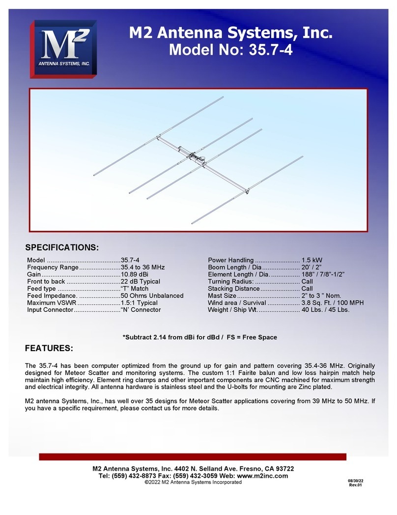
M2 Antenna Systems 6-30LP11 User manual

M2 Antenna Systems

M2 Antenna Systems 6-30LP11 User manual

M2 Antenna Systems 403CP20 User manual

M2 Antenna Systems

M2 Antenna Systems 403CP20 User manual

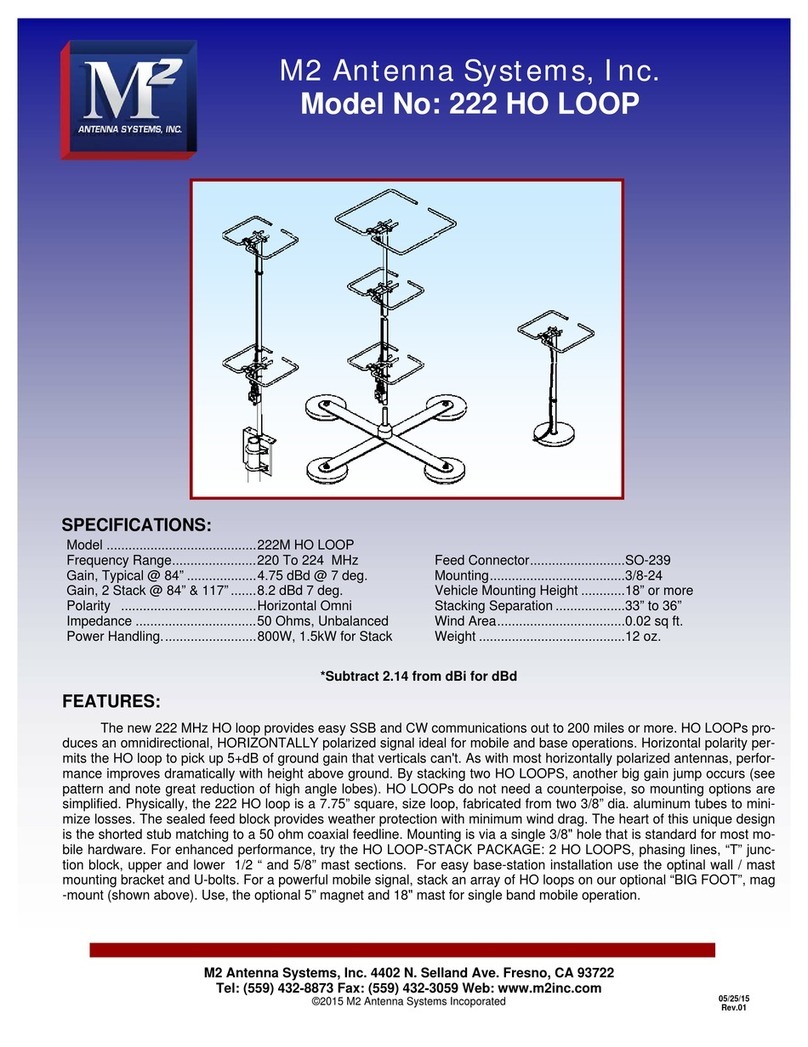
M2 Antenna Systems 222 HO LOOP User manual

M2 Antenna Systems

M2 Antenna Systems 222 HO LOOP User manual

M2 Antenna Systems 902-5 YAGI User manual
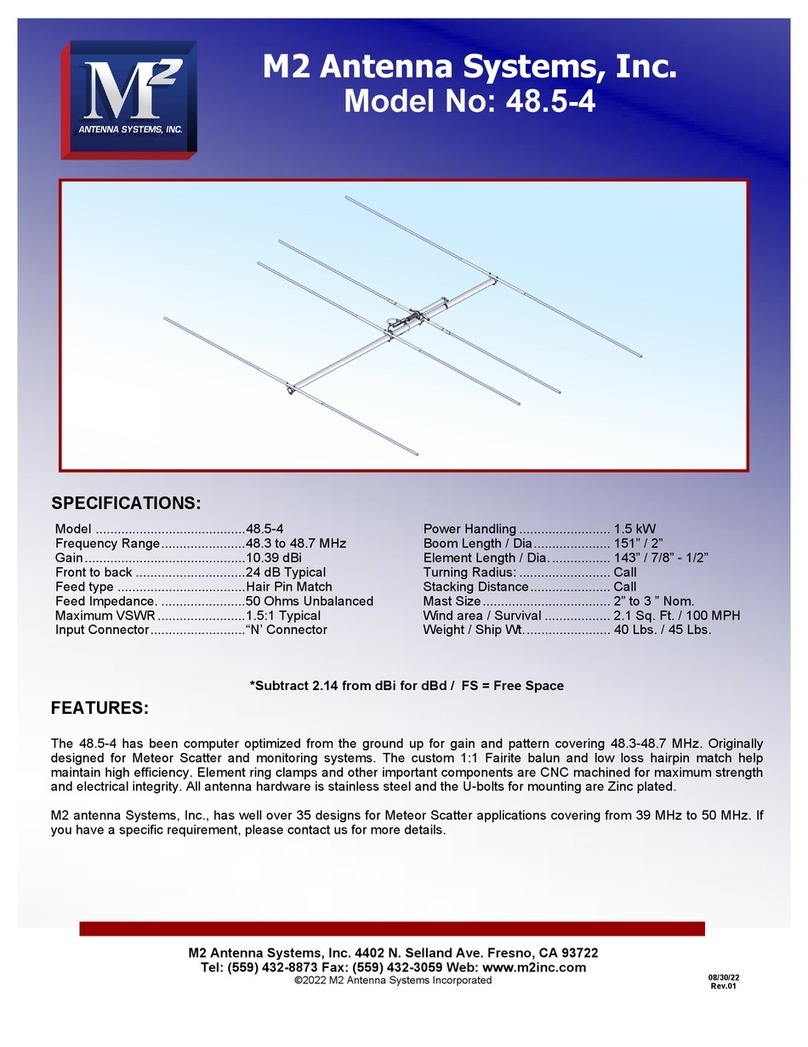
M2 Antenna Systems

M2 Antenna Systems 902-5 YAGI User manual

M2 Antenna Systems 10M7DX User manual

M2 Antenna Systems

M2 Antenna Systems 10M7DX User manual

M2 Antenna Systems 6M-3SS User manual

M2 Antenna Systems

M2 Antenna Systems 6M-3SS User manual

M2 Antenna Systems 222 HO LOOP User manual
M2 Antenna Systems

M2 Antenna Systems 222 HO LOOP User manual

M2 Antenna Systems 440-18 User manual

M2 Antenna Systems

M2 Antenna Systems 440-18 User manual

M2 Antenna Systems 235-11 User manual

M2 Antenna Systems

M2 Antenna Systems 235-11 User manual

M2 Antenna Systems 30M3-125 User manual

M2 Antenna Systems

M2 Antenna Systems 30M3-125 User manual

M2 Antenna Systems 6.9-4CDD-125 User manual

M2 Antenna Systems

M2 Antenna Systems 6.9-4CDD-125 User manual

M2 Antenna Systems 12M4DX User manual

M2 Antenna Systems

M2 Antenna Systems 12M4DX User manual

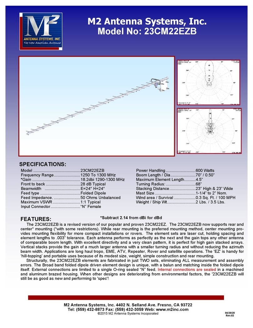
M2 Antenna Systems 23CM22EZB User manual

M2 Antenna Systems

M2 Antenna Systems 23CM22EZB User manual

M2 Antenna Systems 44.5-5 User manual

M2 Antenna Systems

M2 Antenna Systems 44.5-5 User manual

M2 Antenna Systems 32 HO LOOP User manual

M2 Antenna Systems

M2 Antenna Systems 32 HO LOOP User manual

M2 Antenna Systems 248CP22A User manual

M2 Antenna Systems

M2 Antenna Systems 248CP22A User manual

M2 Antenna Systems EB-144/RK2M User manual

M2 Antenna Systems

M2 Antenna Systems EB-144/RK2M User manual

M2 Antenna Systems FG2227-21X4CP User manual

M2 Antenna Systems

M2 Antenna Systems FG2227-21X4CP User manual

M2 Antenna Systems 6M HO LOOP User manual

M2 Antenna Systems

M2 Antenna Systems 6M HO LOOP User manual

M2 Antenna Systems 1700-26-2 User manual

M2 Antenna Systems

M2 Antenna Systems 1700-26-2 User manual

M2 Antenna Systems 41-3BB User manual

M2 Antenna Systems

M2 Antenna Systems 41-3BB User manual

M2 Antenna Systems 7-10-30LP8 User manual

M2 Antenna Systems

M2 Antenna Systems 7-10-30LP8 User manual

M2 Antenna Systems 436CP42UG User manual

M2 Antenna Systems

M2 Antenna Systems 436CP42UG User manual

M2 Antenna Systems 400-800-8 User manual

M2 Antenna Systems

M2 Antenna Systems 400-800-8 User manual

Popular Antenna manuals by other brands

WiMo ULTRABEAM troubleshooting guide

WiMo

WiMo ULTRABEAM troubleshooting guide

Greyline 28 Foot DX Assembly guide

Greyline

Greyline 28 Foot DX Assembly guide

Berker 9490 01 00 Operation and assembly instructions

Berker

Berker 9490 01 00 Operation and assembly instructions

Lectronics M2C instruction manual

Lectronics

Lectronics M2C instruction manual

Televes Ellipse manual

Televes

Televes Ellipse manual

TechniSat ASTRAPLUS SATENNE Installation instruction

TechniSat

TechniSat ASTRAPLUS SATENNE Installation instruction

Falcon EVO user manual

Falcon

Falcon EVO user manual

Ubiquiti airMAX RocketDish quick start guide

Ubiquiti

Ubiquiti airMAX RocketDish quick start guide

COBHAM SAILOR 1000 XTR Ku 8W Field Replacement Procedure

COBHAM

COBHAM SAILOR 1000 XTR Ku 8W Field Replacement Procedure

Meinberg GPSANT manual

Meinberg

Meinberg GPSANT manual

Megasat Caravanman 65 Premium V2 user manual

Megasat

Megasat Caravanman 65 Premium V2 user manual

Total Control UC-A360 manual

Total Control

Total Control UC-A360 manual

Wilson Electronics Cellular Cradle Plus installation guide

Wilson Electronics

Wilson Electronics Cellular Cradle Plus installation guide

NoiseKen THA-380M60G instruction manual

NoiseKen

NoiseKen THA-380M60G instruction manual

Tooway KA-SAT Preliminary Installation Training

Tooway

Tooway KA-SAT Preliminary Installation Training

WisyCom ADFA user manual

WisyCom

WisyCom ADFA user manual

Radio Shack Amplified Upright UHF/VHF/FM Indoor Antenna user guide

Radio Shack

Radio Shack Amplified Upright UHF/VHF/FM Indoor Antenna user guide

Cisco Aironet AIR-ANT2568VG-N quick start guide

Cisco

Cisco Aironet AIR-ANT2568VG-N quick start guide

manuals.online logo
manuals.online logoBrands
  • About & Mission
  • Contact us
  • Privacy Policy
  • Terms and Conditions

Copyright 2025 Manuals.Online. All Rights Reserved.