manuals.online logo
Brands
  1. Home
  2. •
  3. Brands
  4. •
  5. M2 Antenna Systems
  6. •
  7. Antenna
  8. •
  9. M2 Antenna Systems 80M1L User manual

M2 Antenna Systems 80M1L User manual

08/17/11
Rev.00
Model ........................................80M1L
Frequency Range switch able....3.50-3.565 & 3.75-3.82
Gain............................................2.0 dBi Free space
Front to side...............................0 dB
Beamwidth ...............................E=90°
Feed type...................................Direct feed
Feed Impedance........................50 Ohms Unbalanced
Maximum VSWR........................2.0:1
Input Connector..........................SO-239, Other avl.
Power Handling..........................3 kW, Higher avl.
Boom Length / Dia......................N/A
Element Length / Dia..................105 Ft / 3” to 1/2”
Turning Radius:..........................52.5 Ft
Stacking Distance.......................100’ To 160’
Mast Size....................................2” to 3 ” Nom.
Wind area / Survival...................8 Sq. Ft. / 100 MPH
Weight / Ship Wt.........................75 Lbs. / 109 Lbs.
M2 Antenna Systems, Inc.
Model No: 80M1L
FEATURES:
The 80M1L is a reduced sized dipole with great versatility. It has been upgraded both mechanically and electri-
cally. When used as a rotatable dipole, it will easily outperform all fixed wire dipoles. It can also be used as a building
block for future expansion to a 2 or 3 element beam antenna. The dipole can also be separated in half and used as
phased 1/4 wave verticals. Element halves start with 3” diameter tubing and taper through 2”, 1-3/4”, 1-1/2”, 1-1/4”, 1”,
3/4” & 1/2” sections to the 3/8 tips. The 3” and 2” sections are separated by a rugged fiberglass insulator to allow for the
linear loading (3/8” aluminum tubing). A solid 2” O.D. x 36” fiberglass rod, sleeved to the 3” elements, serves as the cen-
ter insulator. This is the same element used in our 80M2L and 80M3L Yagis. Let your imagination go wild. You may come
up with something real different!
The linear loading terminates above the boom and out of the element plane to reduce inductive cancellation and
provide element support. Tip droop is typically 3-4 feet and looks better than some 40 meter elements. The 3 kW, 1:1
balun and phone / CW power switching relay are housed in a water proof fiberglass Hoffman enclosure allowing access
for maintenance and tuning at the center of the element. Relay switching requires 12 VDC @ .15a supply. The system
defaults to phone when not energized.
SPECIFICATIONS:
*Subtract 2.14 from dBi for dBd
M2 Antenna Systems, Inc. 4402 N. Selland Ave. Fresno, CA 93722
Tel: (559) 432-8873 Fax: (559) 432-3059 Web: www.m2inc.com
©2011 M2 Antenna Systems Incoporated
OVERVIEW: Feel free to change order of assembly to fit your space needs.
Once fully assembled or even in pieces, this antenna is LONG. Assemble the center section to the 2”
diameter point. Then assemble the element tip sections from the 1-3/4 inch diameter section out. Use the
length and hardware sizes called out on the DIMENSION AND ASSEMBLY DRAWING. Penetrox (zinc
paste) has been supplied to be used on the threads of bolts and screws, as well as every aluminum joint.
1. Locate the large, 36” long 2 inch diameter fiberglass rod used as center insulator. The rod has 4
bushings or coupling rings and the rod may be labeled to match two 3 " x 180”' inner element
sections.Using four machined 2 inch saddles, attach the center insulator to a 8" x 8" x 1/4" element to
boom plate. Use the 3/8-16 x 3-1/2” stainless bolts and locknuts. Rotate the 2” rod so the holes through
the coupling rings are up or parallel with the plate. Center the insulator on the plate and tighten the 3/8”
hardware.
2. Assemble the center section of each element. Slip on the butt sections and NOTE THE LARGE 1/2”
HOLES AT THE OPPOSITE END OF THE SECTIONS ARE FACING THE SAME DIRECTION. Insert a
1/4-20 x 3-3/4” inch bolt UP through the inner hole and add a plain nut. Use 1/4-20 x 3-1/2 inch bolts and
LOCKNUTS through the outer set of holes. NOTE: The longer inner bolts now form studs where the CW
LOADING/SWITCHING assembly is attached later in the assembly. Tighten all hardware.
3. Locate the 1/2” x 4-1/2 “ aluminum rods and attach the 3/4” square rod tips and secure each with an 8-
32 x 1-1/4” screw and locknut and tighten. Assemble all 4 at this time.
4. Insert the completed rod assembly near the outer end of the 3" sections . Attach with 1/4-20 x 3/4"
bolts and lock washers. BUT DO NOT TIGHTEN YET. Now orient the rod assembly so the 3/8” holes at
the ends are parallel with the element and tighten the bolts. Add the 1/4-20 x 1-1/4” bolts and locknuts
finger tight at this time.
5. Next, install the completed rod assemblies into the 1/2” hole at the butt of the 2” x 48” element
section. Again attach with 1/4-20 x 3/4” bolts and lock washers. Now orient the rod assembly so the 3/8”
holes at the ends are parallel with the element and tighten the bolts. Add the 1/4-20 x 1-1/4” bolts and
locknuts finger tight at this time.
INSULATOR SLEEVE
FIBERGLASS
3/8 X 185" LL TUBE
LINEAR LOADING POST ASSEMBLY
ROD TIP
FOR 3/8" TUBE
AND LOCKNUTS
1/4-20 X 3-1/2"
4 PLCS.
1/2 X 4-1/2"
ALUM. POST 8-32 X 1-1/4"
SCREW AND
LOCKNUT
3" X
180"
BOLT & L.W.
1/4-20 X 3/4"
2" X .125 X 48"
BOLT & L.W.
1/4-20 X 3/4"
8-32 X 1-1/4"
SCREW AND
LOCKNUT
1/4-20 X 1-1/4"
BOLT &
LOCKNUT
80M1L ASSEMBLY MANUAL
6. Insert each 2-3/4 x 8” fiberglass sleeve insulator into the outer end of the 3” element butts and add
the 1-4-20 x 3-1/2” bolts and locknuts finger tight. Now insert the 2” x .125 x 48” section into the
insulator and align the holes. Make sure the 1/2” post assembly installed in step #4, points opposite
from the post assembly in the 3” element section. Add the 1/4-20 x 3-1/2 bolts and locknuts and NOW
TIGHTEN all 4 bolts. Repeat for the other element half.
7. Add a 3/8” x 178” tube to the inner postand a 190” tobe to the outer 2” section, post by inserting the
3/8” tube through the hole about 1 inch, and tighten the 1/4-20 x 1-1/4” bolt and locknut. Continue until
you have all 4 tubes attached and secured.
8. Loosely install five (5) 1/4-20 x 1” bolts and locknuts in pairs of “linear loading shorting bars”. Refer
to the DIMENSION SHEET for the shorting bar positions for the linear loading tubes. Use a permanent
marking pen or a ring of masking tape to mark the shorting bar position on the 3/8” tubes. Prepare the
5/16” turnbuckles by removing the “hook” end of each turnbuckle and add a 5/16-18 nut on the threads
all the way to the hook. Now replace the hook end into the turnbuckle body and adjust the threaded
ends so that just one thread “shows” inside the body of the turnbuckle. Add a 1/4” cable eye to each
“eye” of the turnbuckles. Now hook the turnbuckles into the turnbuckle plate.
9. Refer to the TYPICAL HARDWARE ARRANGEMENT drawing. Slide one loosely assembled
shorting bar pair onto the two tubes to the marks. Tighten one outside screw just enough to hold the
shorting bar in position. Insert the 18” section of HPTG-4000 Phillistran cord into the two center
grooves in the shorting bar pair and around strain relief. Note one groove is dead center and the other
is offset. The long end of the cord should come out the “centered” groove. The short end should loop
around the strain relief and come back out about 2”. Now tighten the rest of the screws in the shorting
bars.
NOTE: IT MAY BE HELPFUL TO INSTALL A TEMPORY MAST OF 1-1/2 TO 2” DIA. TUBE TO
ADJUST THE LINEAR LOADING TENSIONING SYSTEM PRIOR TO ASSEMBLY ON YOUR MAST.
SET THE FLAT PART OF THE TURNBUCKLE PLATE ABOUT 33” ABOVE THE ELEMENT.
10. Route the black cord around the thimble in the turnbuckle eye and back on itself. Keep this length
between the eye and the shorting bar pair no more than 3” in length. Now lift the linear loading tubes
and pull the cord until the tubes are under tension. Install the cable clips around all three cords and
tighten the clips.
8-32 X1-3/4" SCREW
1-1/2" X.058 X 60" SOE
HOOK TAPE MEASURE HERE
TUNING DIMENSION
( start at 163" )
SHORTING BAR PAIRS
STRAIN RELIEF
HALF ELEMENT DETAIL
1/4-20 X 2-1/2"BOLT
2" x.125 x48"
ALLOW 1" PAST BAR
AND TRIM OFF EXCESS
1-3/4 x.058x 60"SOE
8-32 X 2" SCREW
~19.00"
CABLE EYE
( THIMBLE )
1/4" 'CLIPS' 1/4-20 X 1"
BOLTS &
LOCKNUTS
2"x .125 x48"
8-32X 1-1/4"SCREW
3/4 X .049 X 48" SOE
8-32 X 1-1/2" SCREW
1-1/4 X .058 X 60" SOE
1" X .058 X60"SOE
1/2 X .049X 60"
2-3/4" X 8"
FIBERGLASS
SLEEVE
80M1L ASSEMBLY MANUAL
REFER AGAIN TO THE “TYPICAL HARDWARE ARRANGEMENT DRAWING.
13. Mount the CW loading COIL, RELAY AND 1:1 BALUN HOUSING by attaching the two mounting plates to the
“bottom” of the housing using 10-32 x 3/8” screws . Then attach the housing assembly to the two element halves
using two 3” U-bolts, saddles, 3/8-16 stainless nuts and lockwashers. Center it and tighten the U-bolts slightly.
Now add the connecting straps between the inner bolts at the butt of each element half over to the studs on the
housing. Secure using flat washers and 1/4-20 locknuts. (IF THE PHONE CW RELAY IS NOT USED, ATTACH A
1:1 BALUN ON THE STUDS AT THE BUTTS OF THE ELEMENTHALVES.
14. Attach the 12 VDC leads to the two inner terminals on the down side of the housing. (no polarity requirement).
Use RG-58 coax putting +12 VDC on the center conductor. The shield goes to the negative terminal of your
power supply. Or use #22 AWG (minimum) twisted, SHIELDED pair to carry the 12 VDC and ground shield at
supply. Ground shield at shack end. Apply voltage only when you want to operate in the low CW part of the band.
When the relay is not activated the coil loading is bypassed.
15. Connect good quality 50 Ohm coax to the connector on the housing. NOTE THE TWO BLOCK CONNEC-
TIONS ON EITHER SIDE OF THE RF CONNECTOR. These are used for the hairpin match adjustment on the
80M2LLA and the 80M3LLA Yagis. The dipole match should be close to 50 Ohms (depending on height above
ground, but 3/8” tubes and an appropriate shorting bar could be added here if you match is disturbed by sur-
rounding objects on the tower / mast or height over ground. Caution: these block connectors are HOT with RF
when you transmit.
THIS COMPLETES THE ASSEMBLY.
TUNEUP: If possible raise the dipole to its normal height and take a measurement to determine the resonant fre-
quency. Alternately get the dipole at least 30 feet high and in the clear and remember it will probably go a little
higher in frequency once it is raised to its final height. If the resonant frequency is below 3.750, reduce the
“TUNING DIMENSION” or slide the 3/8” tip sections in 1 inch at a time. If it is resonant too high, increase the tip
dimension. The resonant frequency moves at a rate of about 8.5 to 9 KHz per inch of adjustment.
This Antenna will have the most effect on 20 meter antennas. If possible locate it on a separate tower or at
least orient it in parallel with the boom of the 20 meter antenna. It can be mounted just a few feet from other an-
tenna boom and elements. These objects can affect the minimum VSWR and the resonant frequency. It is best to
do the final tuning in its permanent location.
DO NOT SWITCH FROM PHONE TO CW WHILE TRANSMITTING AS DAMAGE TO THE RELAY IS
POSSIBLE. The 1:1 balun is constructed of Teflon coax and uses NO ferrite. It is rated at 5000 Watts, continu-
ous. Contact the factory for higher power options.
CAREFULLY MANUFACTURED BY:
M2ANTENNA SYSTEMS, INC.
4402 N. Selland Ave.
FRESNO, CA 93722
(559) 432-8873 FAX (559) 432-3059
www.m2inc.com Email: [email protected]
80M1L ASSEMBLY MANAUL
3/8-18 NUT
& LOCKWASHER
8 PLCS.
2" HD U-BOLT
2 PLCS.
8" X 8"
2" X 36" FIBERGLASS
AND COUPLING RINGS.
CENTER INSULATOR
3" U-BOLT &
SADDLE, 2 PLCS.
3/8 -16 NUTS &
LOCKWASHERS,
SS, 4 PLCS.
HOUSING
MOUNTING PLATE
2 PLCS.
(4) 2" HD
SADDLES
2 PLCS.
MTG PLATE
HPTG 4000
PHILISTRAN,
2 CLIPS AND
STRAIN RELIEF
(EACH SIDE)
YOUR MAST
2" STANDARD U-BOLT
CONNECTING
STRAPS, 2 PLCS
RELAY / COIL
& BALUN
HOUSING
DIPOLE
ELEMENT
(4) 3/8-16 x 3-1/2"
BOLT & LOCKNUT
2 PLCS.
& FLATWASHER
1/4-20 LOCKNUT
1/4-20 X 3-1/2
BOLT & LOCKNUT
1/4-20 X 3-3/4"
BOLT, FLATWASHER,
STRAP, FLATWASHER
AND LOCKNUT, SS
3" X 15'
ELEMENT
2 PLCS.
LINEAR LOADING (LL)
3/8 DIA. ALUM. TUBE
2 PC SHORTING BARS
BOLT,1/4-20 X 1" AND
1/4-20 LOCKNUTS
TURNBUCKLE
'"L" PLATE
80M1L ASSEMBLY DETAIL
WE RECENTLY RE-DESIGNED THE PHONE –CW RELAY AND COIL HOUSING AND GENERAL
ASSEMBLY. This was done to make manufacture easier and to allow customer modification and main-
tenance. We now use a fiberglass enclosure that can be opened for inspection, repair or modification.
Looking inside the housing you will see that we have provided two holes in the coil leg that attaches to
the relay. Generally the easiest way to move the frequency of the element when the coil is engaged, is
to change the inductance of the coil by spreading it. Quite a wide range of inductance can be achieved
by lengthening or shortening the coils. They are set to be just under 2.5 uHy from the factory. By shift-
ing to the other holes in the coil legs, the inductance can be dropped to about 2.3 uHy. This will shift
operation up the band about 50 kHz. You may also have to physically open the coil since it is springy
and make sure all the turns are evenly spaced. Larger movement in frequency can be achieved by re-
moving turns, however you should do some calculations first or contact the factory to avoid seriously
degrading the bandwidth, or performance of the antenna. The antenna has been modeled in Brian
Beezley’s AO “PRO” ,version 6.5. Linear loading will not necessarily model correctly in NEC based
programs. AO is Mininec based and does much better at modeling parallel wires than NEC.
What about coils in the place of the linear loading? Several hams have had another group modify our
Yagi to eliminate the linear loading and convert to coils. The boom is also lengthened by about UP TO
18 feet. This results in a gain improvement of .8-.9 dB and this is not due to the coils, but to the added
boom length AND NARROW BANDING.. We have modeled both coils and linear loading and when all
other parameters are equal, the performance is virtually the same. One big But remains however. The
“Q” of the coils used must be over 600. This is very difficult and expensive to do. For those of you
who have structural or local weather concerns, you should know we are planning on producing a coil
version of the 80M3. We are doing this carefully and slowly. We are also planning on offering a longer
boom version of the 80M3. As always, we like to make changes in such a way that past owners can
upgrade. We will continue to review customers desires and at some point, if some want or need coils or
a longer boom, or both, we will make what our customers request.
We just don’t want you to be misled by a few random, uncontrolled on the air tests that show one an-
tenna to be better than the other. So many parameters are at play that it is easy to come to the wrong
conclusion. Height above ground, local terrain, location in the world or in the United States, feedline
loss and of course, the RF power delivered to the antenna all can have massive effects on test com-
parisons.
Enjoy your 80M1L and call me if you have questions or concerns.
73, Mike Staal, K6MYC
ADJUSTING / CUSTOMIZING YOUR 80M YAGI
DESCRIPTION ........................................................QTY.
3 x .125 x 180" alum. tube ......................................2
Center Insulator assembly, 2" fiberglass w. rings ....1
Fiberglass Sleeve Insulator, 2.75 x 8” ......................2
2 x .125 x 48" alum. tube .........................................2
1-3/4 x .058 x 60" alum tube SOE ............................2
1-1/2 x .058 x 60" alum. tube SOE .........................2
1-1/4 x .058 x 60" alum. tube SOE ..........................2
1 x .058 x 60" alum. tube SOE ...............................2
3/4 x .049 x 48" alum. tube SOE ..............................2
1/2 x .049 x 60” alum. tube, STR..............................2
3/8 x .049 x 36”.........................................................2
3/8 X .049 X 185” linear loading tube .......................4
Element mounting plate 8 x 8 x 1/4 alum. ...............1
U-bolt, 2" heavy duty ..............................................4
U-bolt, standard, 2" ..................................................1
Assembly instructions...............................................1
SMALL PARTS BOX / BAG
Linear Loading Support Rod, alum. 1/2 x 4-1/2".......4
Rod tip, 3/4 sq. x 2” ..................................................4
Shorting bar halves, 1/4 x 3/4 x 7.25” machined ......4
Strain relief, 1/2” x 1/2” (Black Delrin).......................2
Saddle, 2’ heavy duty, machined, aluminum............4
Turnbuckle angle plate, HD 1/4”...............................1
Turnbuckle, 5/16” hook and eye...............................2
Penetrox, (zinc paste) ..............................................1
Cable, Phillistran HPTG 4000 x 18”..........................2
Compression Clamp, 5/8” ........................................2
Compression Clamp, 1/2”.........................................2
80M1L PARTS & HARDWARE
IN HARDWARE BAGS............................................QTY
Bolt, 3/8-16 x 3-1/2...................................................4
Locknut, 3/8-16, ss...................................................4
Nut 3/8-16 ss ...........................................................12
Lock washer, 3/8 split ring, ss ..................................12
Nut 5/16-18 ss .........................................................4
Lock washer, 5/16" split ring ss ...............................2
Bolt 1/4-20 x 3-3/4" hex cap ss ...............................2
Bolt 1/4-20 x 3-1/2" hex cap ss ...............................10
Bolt 1/4-20 x 2-1/2" hex cap ss ................................4
Bolt, 1/4-20 x 1-1/4”, ss ...........................................4
Bolt 1/4-20 x 1" hex cap ss ......................................10
Bolt 1/4-20 x 3/4" hex cap ss ...................................4
Nut 1/4-20 locking ss ..............................................32
Nut, 1/4-20, ss, plain.................................................2
Washer, 1/4”, flat ss ................................................4
Lock Washer, 1/4”, split ring, ss ...............................4
Screw 8-32 x 2" pan hd ss........................................4
Screw 8-32 x 1-3/4" pan hd ss ................................4
Screw 8-32 x 1-1/2" pan hd ss ................................4
Screw 8-32 x 1-1/4" pan hd ss ................................8
Screw 8-32 x 1/2” pan hd. ........................................4
Locknut 8-32 ss .....................................................38
Nut 8-32, ss..............................................................4
Wire clip, 1/4”............................................................4
Thimble, (cable eyes) 1/4”........................................2
PHONE-CW RELAY ASSEMBLY (kit separate)
CW Relay-coil-balun housing ( with connector ).......1
Mounting plates (for housing)...................................2
Jumper strap (for coil housing connections).............2
U-bolt, 3”...................................................................2
Nut 3/8-16 ss ...........................................................4
Lock washer, 3/8 split ring, ss ..................................4
Screw, 10-32 x 3/8” ss .............................................4
CAREFULLY MANUFACTURED BY:
M2ANTENNA SYSTEMS, INC.
4402 N. Selland Ave.
FRESNO, CA 93722
(559) 432-8873 FAX (559) 432-3059
www.m2inc.com Email: [email protected]
80M1L PARTS & HARDWARE

Other M2 Antenna Systems Antenna manuals
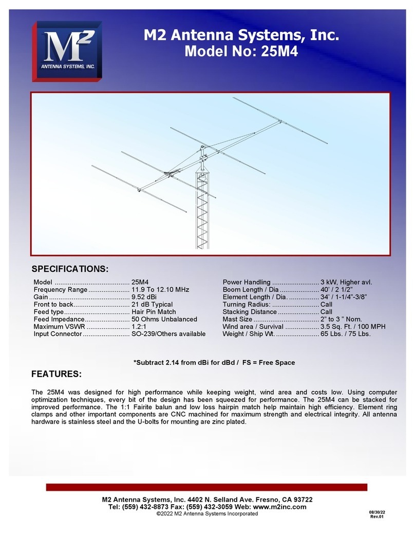
M2 Antenna Systems 25M4 User manual

M2 Antenna Systems

M2 Antenna Systems 25M4 User manual

M2 Antenna Systems 406-6SX User manual

M2 Antenna Systems

M2 Antenna Systems 406-6SX User manual

M2 Antenna Systems 137CP14HD User manual
M2 Antenna Systems

M2 Antenna Systems 137CP14HD User manual

M2 Antenna Systems Relay/Preamp Housing with MAP65 User manual
M2 Antenna Systems

M2 Antenna Systems Relay/Preamp Housing with MAP65 User manual

M2 Antenna Systems 20M6-125 User manual

M2 Antenna Systems

M2 Antenna Systems 20M6-125 User manual

M2 Antenna Systems 40M3C User manual

M2 Antenna Systems

M2 Antenna Systems 40M3C User manual

M2 Antenna Systems 215-470LP16 User manual

M2 Antenna Systems

M2 Antenna Systems 215-470LP16 User manual

M2 Antenna Systems 400-800-8 User manual

M2 Antenna Systems

M2 Antenna Systems 400-800-8 User manual

M2 Antenna Systems 30M3-125 User manual

M2 Antenna Systems

M2 Antenna Systems 30M3-125 User manual

M2 Antenna Systems 7-10-30LP8 User manual

M2 Antenna Systems

M2 Antenna Systems 7-10-30LP8 User manual

M2 Antenna Systems 44.5-5 User manual

M2 Antenna Systems

M2 Antenna Systems 44.5-5 User manual

M2 Antenna Systems 75-5AS User manual

M2 Antenna Systems

M2 Antenna Systems 75-5AS User manual

M2 Antenna Systems 400CP30A User manual

M2 Antenna Systems

M2 Antenna Systems 400CP30A User manual

M2 Antenna Systems FG170-230-5 User manual

M2 Antenna Systems

M2 Antenna Systems FG170-230-5 User manual

M2 Antenna Systems 6M6LN User manual

M2 Antenna Systems

M2 Antenna Systems 6M6LN User manual

M2 Antenna Systems 440-6SX User manual

M2 Antenna Systems

M2 Antenna Systems 440-6SX User manual

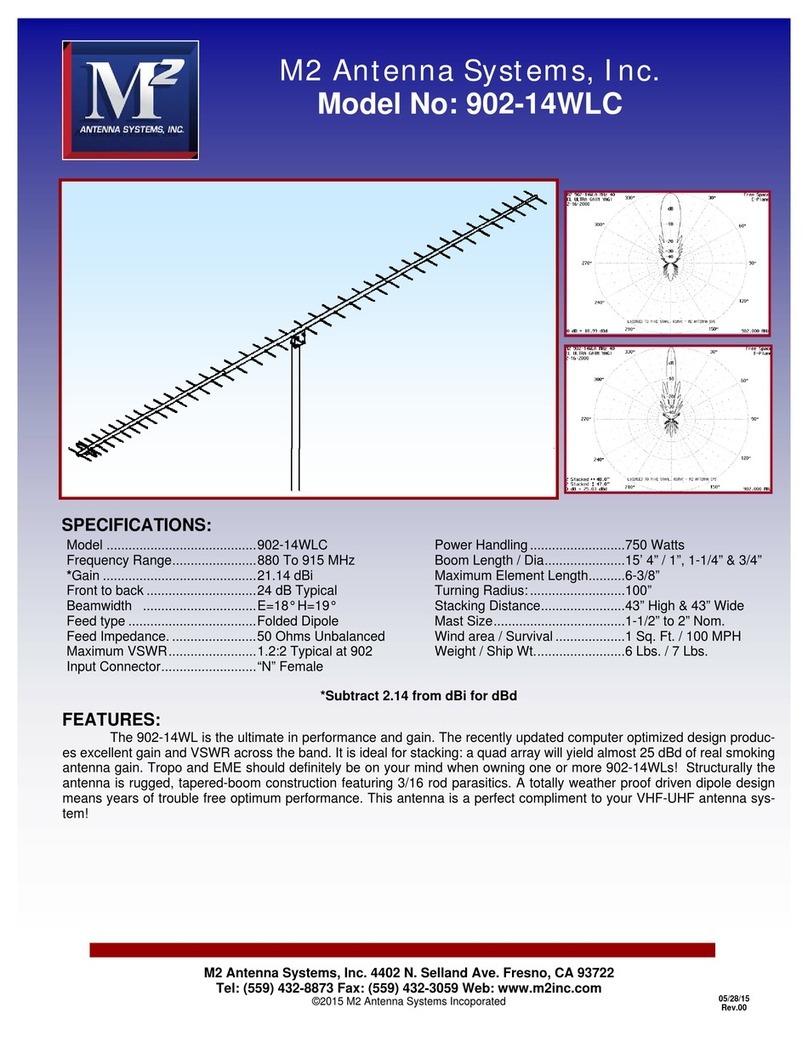
M2 Antenna Systems 902-14WLC User manual

M2 Antenna Systems

M2 Antenna Systems 902-14WLC User manual

M2 Antenna Systems 418CP30 User manual

M2 Antenna Systems

M2 Antenna Systems 418CP30 User manual

M2 Antenna Systems 222 HO LOOP User manual

M2 Antenna Systems

M2 Antenna Systems 222 HO LOOP User manual

M2 Antenna Systems 8-30LP9 User manual

M2 Antenna Systems

M2 Antenna Systems 8-30LP9 User manual

M2 Antenna Systems 40M2C User manual

M2 Antenna Systems

M2 Antenna Systems 40M2C User manual
M2 Antenna Systems 6-30LP11 User manual

M2 Antenna Systems

M2 Antenna Systems 6-30LP11 User manual

M2 Antenna Systems 300XP12 User manual

M2 Antenna Systems

M2 Antenna Systems 300XP12 User manual

M2 Antenna Systems 10M7DX User manual

M2 Antenna Systems

M2 Antenna Systems 10M7DX User manual

Popular Antenna manuals by other brands

Chameleon Antenna CHA EMCOMM II V2 Operator's manual

Chameleon Antenna

Chameleon Antenna CHA EMCOMM II V2 Operator's manual

SLX 64 Element Digital TV Aerial Kit User guid

SLX

SLX 64 Element Digital TV Aerial Kit User guid

COBHAM Sea Tel quick start guide

COBHAM

COBHAM Sea Tel quick start guide

Directive Systems & Engineering DSE3319LYK quick start guide

Directive Systems & Engineering

Directive Systems & Engineering DSE3319LYK quick start guide

Intellian i9P Installation and operation manual

Intellian

Intellian i9P Installation and operation manual

Sqish MG-4000VHQ user manual

Sqish

Sqish MG-4000VHQ user manual

PCTEL WLP2458NGP installation instructions

PCTEL

PCTEL WLP2458NGP installation instructions

Verizon SC-LTE-V user manual

Verizon

Verizon SC-LTE-V user manual

PNI ML100 User instruction

PNI

PNI ML100 User instruction

Emos J0657 manual

Emos

Emos J0657 manual

Ubiquiti air MAX Omni quick start guide

Ubiquiti

Ubiquiti air MAX Omni quick start guide

Clear TV Key X-70B HDTV DIGITAL instructions

Clear TV

Clear TV Key X-70B HDTV DIGITAL instructions

M2 917A-ISP YAGI manual

M2

M2 917A-ISP YAGI manual

Sutron DRGS installation guide

Sutron

Sutron DRGS installation guide

Sirio Antenne SKA 47/135 installation manual

Sirio Antenne

Sirio Antenne SKA 47/135 installation manual

RCA ANT301R Limited warranty

RCA

RCA ANT301R Limited warranty

Sanav MU-201S3E user manual

Sanav

Sanav MU-201S3E user manual

BAS BAS-2333 LOGO-700 manual

BAS

BAS BAS-2333 LOGO-700 manual

manuals.online logo
manuals.online logoBrands
  • About & Mission
  • Contact us
  • Privacy Policy
  • Terms and Conditions

Copyright 2025 Manuals.Online. All Rights Reserved.