manuals.online logo
Brands
  1. Home
  2. •
  3. Brands
  4. •
  5. M2 Antenna Systems
  6. •
  7. Antenna
  8. •
  9. M2 Antenna Systems 40M2C User manual

M2 Antenna Systems 40M2C User manual

M2 Antenna Systems, Inc. 4402 N. Selland Ave. Fresno, CA 93722
Tel: (559) 432-8873 Fax: (559) 432-3059 Web: www.m2inc.com
©2021 M2 Antenna Systems Incorporated 05/017/21
Rev.01
Model ........................................ 40M2C
Frequency Range ...................... 7.0-7.3 MHz 3 Seg
Gain ........................................... 11 dBi @ 70’ / 6.1 FS
Front to back .............................. 25 dB @ 70 ft / 15 FS
Beamwidth ............................... E=74°
Feed type ................................... Hair pin match
Feed Impedance. ....................... 50 Ohms Unbalanced
Maximum VSWR ....................... See Curve
Input Connector ......................... SO-239, Other avl.
Power Handling.......................... 3 Kw PEP, Higher avl.
Boom Length / Dia ..................... 19.5’ / 3.0 x .065 Wall
Element Length / Dia. ................ 50 Ft. / 1-1/2” To 1/2”
Turning Radius:.......................... 27 Ft.
Stacking Distance ...................... 70 Ft.
Mast Size ................................... 2” to 3 ” Nom.
Wind area / Survival................... 4.85 Sq. Ft. / 100 MPH
Weight / Ship Wt. ....................... 76 Lbs. / Lbs.
M2 Antenna Systems, Inc.
Model No: 40M2C
SPECIFICATIONS:
*Subtract 2.14 from dBi for dBd
FEATURES:
The 40M2C is the latest addition to our already exceptional 40 meter Yagi lineup. Using all the latest design and manufacturing tools,
including 3D printed coil forms. Our coil loaded antennas now make it difficult to choose a full size equivalent. Mounting this Yagi at 70
feet creates incredibly clean pattern with unique front to rear and above performance.
Our new covered coil design features 3/16" diameter copper clad soft drawn aluminum that has great power handling and high efficien-
cy (Q over 900) combined with low weight. We use 3D printing for precision coil forms. The coils are located at the optimum place in
each element half. The location of the coil is important for best performance and this careful placement also breaks the element into
small electrical lengths that appear shorter than 20 meter elements. This means there is little or no interaction with any 20 meter Yagi
on the same mast OR on the same boom. Our new DUAL BAND "CYCLE BUSTER " takes full advantage of this unique feature.
Mechanically, the coil loading offers a cleaner look with less wind area and fewer connections. Wind and ice loading are reduced as
well. We continue to offer the same unbreakable element mounting and OVER HEAD element support. The rugged, time tested ele-
ments and 3 kW 1:1 Balun are part of the package. All Hardware is stainless steel except for the Galvanized U-bolts and saddles.
(Stainless U-bolts tend to Gall and freeze up) and used in our other 40M Yagis.
40M2C ANTENNA OVERVIEW
BEFORE YOU BEGIN: Look over all the DRAWINGS to get familiar with the various parts and assem-
blies in the system. Tools handy for assembly process: screwdriver, 11/32”, 7/16”, 1/2”, 9/16” and 5/8”
spin-tites, end wrenches and/or sockets, and a measuring tape.
Note:
All installations are unique in some way, which means it's OK to preassemble certain hardware, or
rearrange the assembly process to meet specific site requirements. A quick review of the assembly
drawings should help firm up the appropriate strategy. Please remember to double-check all hard-
ware for tightness BEFORE it becomes inaccessible.
One container of zinc paste (Penetrox, Noalox, or equiv.) has been provided to enhance and
maintain the quality of all mechanical and electrical junctions on this system. Apply a thin coat
wherever two pieces of aluminum come in contact or any other electrical connections are made.
It is also useful on screws and bolt threads as an ANTI SEIZE compound.
DRIVEN
ELEMENT
REFLECTOR
40M ELEMENT HALF OVERVIEW
ELEMENT MOUNTING
PLATE
(M2AEC0040)
ELEMENT CLAMP
(M2AMC0136)
ELEMENT SECTION #1
(M2AEP40MC-1)
ELEMENT SECTION #4
(M2AEP40MC-4)
ELEMENT SECTION
#3
(M2AEP40MC-3)
ELEMENT SECTION #5
(M2AEP40MC-5)
ELEMENT TIP
(SAEL40M2C)
LENGTH VARIES
DEPENDING
ON ELEMENT
2 (QTY) SCREW,
8-32 X 1”
& LOCK NUT
ELEMENT SECTION #6
(M2AEP40MC-6)
COIL ASSEMBLY
2 (QTY) SCREW,
8-32 X 1-1/2”
& LOCK NUT
2 (QTY) SCREW,
8-32 X 1-3/4”
& LOCK NUT
BOLT,
1/4-20 X 2”
& LOCK NUT
ELEMENT ELEMENT
OVERHAED SUPPORT
(M2APL0212)
40M COIL OVERVIEW
40M COIL
(M2ACA1550)
COIL SUPPORT
(M2ACA1554)
COIL INSULATOR
(M2AFG0050)
COIL POST
(M2ACA1551)
(QTY 2)
ELEMENT SECTION #6
(M2AEP40MC-6)
COIL END CAP
(M2ACA1552)
(QTY 2)
ELEMENT SECTION #4
(M2AEP40MC-4)
NOTE: COVER REMOVED FOR ILLUSTRATION PURPOSES.
BOOM ELEMENT TIP
40M COIL ASSEMBLY
INSTRUCTIONS
STEP 1:
The coil comes wound tight with 16 total turns from the factory, When final
assembled, you will end with 15.5 total turns. The excess material will be
trimmed off after the coil is in its final position. Using a permanent marker, draw a
straight line from one end of the coil to the other. This will help later to determine if
your coil has grown in diameter during assembly. After final positioning of the coil,
no more 3/4 of an inch of line tilt is allowed. A larger coil will cause the inductance to
change which can cause your antenna to be off frequency.
STEP 2:
The COIL is wound tight at the factory to prevent damage during shipping. Use the
COIL SPREADING TOOL provided, and carefully insert it into the first turn of the
COIL. Now gently push or roll the tool through all 16 turns of the COIL. Now the
COIL is nearly in its final shape and is ready to be threaded onto the COIL SUP-
PORT. Note the reference line drawn earlier, it will have a slight tilt after spreading.
STEP 3:
On one end, use pliers to gently straighten the last 1/2” of the COIL and file
off any burrs.
STEP 4:
Begin threading the COIL onto one end of the COIL SUPPORT. BE CAREFUL to not deform the COIL during this
process. The COIL should thread smoothly. Continue until about 5-1/2 turns are past the COIL SUPPORT or close to the
center. Exact centering is not important. Again, note your reference line.
NOTE: PENETROX PASTE FOR LUBRICATING SCREW THREADS AND TUBING JOINTS HAS BEEN SUPPLIED. USE A VERY SMALL AMOUNT ON
EACH SCREW THREAD AND UNDER THE COIL POSTS DURING THE NEXT OPERATION.
STEP 5:
Insert the COIL INSULATOR (M2AFG0050) into your COIL SUPPORT (M2ACA1554). Rotate the COIL and the
COIL SUPPORT so the leading end of the COIL goes over and just past the inner hole in the COIL INSULATOR. Now slide
on one COIL POST on to one end of the COIL so it is right over the first hole. Next, carefully slide on the ELEMENT SEC-
TION #6 (M2AEP40MC-6) and align it so both holes in the tube match the two holes in the COIL INSULATOR.
STEP 6:
Insert hardware through the ELEMENT SECTION #6 and the COIL INSULATOR and begin threading it into the
COIL POST. Tighten hardware. Thread the SET SCREW into the top of the COIL POST and with about 1/2” of wire protrud-
ing past the COIL POST, tighten the SET SCREW gently. Use supplied ALLEN WRENCH to tighten the SET SCREW.
1/2” TO 3/4”
TILT
40M COIL ASSEMBLY
INSTRUCTIONS
STEP 7:
The second COIL POST is mounted on the OP-
POSITE SIDE of the COIL INSULATOR so 15 1/2 turns of
the COIL are used. The extra 1/2 turn COIL should pass
over the COIL INSULATOR hole. Slide on the second
COIL POST and align it over the hole. Slide on ELEMENT
SECTION #4 (M2AEP40MC-4) and fasten the COIL POST
to the tubing assembling using the supplied hardware. Use
you reference line and adjust the coil so the line has no
more tilt the 3/4”. There should be about 1.5 to 2” of extra
coil material past the post after adjusting that will be
trimmed.
STEP 8:
Insert the SET SCREW into the COIL POST and
tighten gently. Adjust the COIL and COIL SUPPORT loca-
tion for equally spaced turns. The distance between each
turn should be the same as the COIL wire diameter. Once
the COIL is straight and aligned, tighten the final SET
SCREW securely. Trim off excess coil material leaving 1/4
to 1/2” past the COIL POSTS.
STEP 9:
Slide COIL COVER and COIL END CAPS onto COIL ASSEMBLY. Secure COIL END CAPS into position by securing
hardware through TUBE ASSEMBLIES on both ends of the COIL ASSEMBLY. Slide ELEMENT OVERHEAD SUPPORT onto
ELEMENT SECTION until it reaches the head of the screw holding on the COIL COVER. Clamp ELEMENT OVERHEAD SUP-
PORT in place with screw and locknut.
STEP 10:
Assemble all the remaining COIL ASSEMBLIES by repeating steps 1-9. Set COIL ASSEMBLIES aside for future use.
COIL (15.5 TURNS)
(M2ACA1550)
COIL INSULATOR
(M2AFG0050)
COIL SUPPORT
(M2ACA1554)
ELEMENT SEC-
TION #4
ELEMENT SECTION #6
(M2AEP40MC-6))
COIL POST
(M2ACA1551)
SCREW, 8-32 X 1-1/4”
SET SCREW, 1/4-20 X 1/4”
STEP 11:
At this point it will be helpful to perform the remaining
assembly steps with the BOOM ASSEMBLY elevated off the
ground (about 3 feet). This can be accomplished by using
sawhorses or something similar. Wipe off the swedged ends of
each BOOM SECTION and apply a small amount of PENTROX.
Refer to the drawing below and assemble BOOM SECTIONS as
shown. Insert hardware and tighten.
SCREW, 1/4-20 X 3-1/2”
LOCKNUT, 1/4-20
BOOM
SECTION
BOOM
SECTION
40M2C BOOM ASSEMBLY
INSTRUCTIONS
BOOM SECTION #2
(M2ABS40M2-2)
(QTY 1)
REAR OF
BOOM
FRONT OF
BOOM
BOOM SECTION #3
(M2ABS40M2-3)
(QTY 1)
BOOM SECTION #1
(M2ABS40M2-1)
(QTY 1)
STEP 12:
Assemble the ELEMENT MOUNT
assemblies for the reflector and front director
element. Refer to the assembly drawing to aid in
assembly. Be sure to center the ELEMENT
CENTER SPLICE and the holes are in the
vertical position.
STEP 13:
Assemble the DRIVEN ELEMENT
MOUNT assembly for the DRIVEN ELEMENT.
Refer to the assembly drawing to aid in assembly.
Be sure to center the INSULATOR and the hole
are in the vertical position. The DISC
INSULATORS are a press fit. Heating them with
a heat gun or hot water will help in assembly.
NOTE: For the final assembly on all the ele-
ments, it is best to perform the next steps on the
ground or long flat surface. This will aid during
40M2C ELEMENT MOUNT ASSEMBLY
INSTRUCTIONS
BOLT, 1/4-20 X 2-3/4”
LOCKNUT, 1/4-20
(QTY 4)
ELEMENT MOUNTING
PLATE
(M2AEC0040)
(QTY 2)
ELEMENT CENTER SPLICE
(M2ASR0050)
ELEMENT MOUNT ASSEMBLY
REFECTOR OR DIRECTOR
BOLT, 1/4-20 X 2-1/2”
LOCKNUT, 1/4-20
(QTY 4)
CRADLE 3”
(M2AMC0136)
(QTY 2)
VERTICAL RISER
ASSEMBLY
(SAVR0010)
BOLT, 1/4-20 X 3-1/2”
AND LOCKNUT
(QTY 2)
CRADLE 3”
(M2AMC0136)
(QTY 2)
ELEMENT MOUNTING
PLATE
(M2AEC0040)
(QTY 2)
BOLT, 1/4-20 X 2-1/2”
LOCKNUT, 1/4-20
(QTY 4)
INSULATOR
(M2AFG0034)
VERTICAL RISER
ASSEMBLY
(SAVR0010)
BALUN BRACKET
(M2APT0016)
DISC INSULATOR
(M2ADI0020)
(QTY 2)
ELEMENT MOUNT ASSEMBLY
DRIVEN ELEMENT
BOLT, 1/4-20 X 2-3/4”
LOCKNUT, 1/4-20
(QTY 4)
BOLT, 1/4-20 X 3-1/2”
AND LOCKNUT
(QTY 2)
final adjustment of the ELEMENT OVER HEAD SUPPORT. The ELEMENT HALVES are symmetrical on both sides. Do
each of the following steps on both sides of the ELEMENT.
STEP 14:
Slide ELEMENT SECTION #2 onto ELEMENT CENTER SPLICE or INSULATOR.
STEP 15:
Slide ELEMENT SECTION #1 onto ELEMENT SECTION #2. Insert hardware and tighten locknut. Attach VERTI-
CAL RISER ASSEMBLY. For the driven element you need to add (4) CLAMP BLK, 3/8 (HAIRPIN) (M2AMC0261) and
hardware. See drawings for hardware call out for the different elements.
STEP 16:
Insert ELEMENT SECTION #3 into the end of ELEMENT SECTION #1. Insert and tighten hardware.
STEP 17:
Insert the ELEMENT SECTION #6 of the COIL ASSEMBLY previous assembled in STEPS 1-10 into ELEMENT
SECTION #3. Insert and tighten hardware.
STEP 18:
Insert ELEMENT SECTION #5 into the end of ELEMENT SECTION #4. Insert and tighten hardware.
STEP 19:
To be able to adjust the ELEMENT TIP, a COMPRESSION CLAMP is used. First thread on the hex nut to capture
the screw in the CLAMP. Then slide the COMPRESSION CLAMP such the screw is lined up with the hole in ELEMENT
SECTION #5. Use the DIMENSION SHEET and set the proper exposed length of the 1/2” ELEMENT TIP for the appropri-
ate element, then mark the element assembly to avoid confusion later. See GENERIC COMPRESSION CLAMP DETAIL
page for more detail.
STEP 20:
Tensioning the element over head guys: See the LOCK BLOCK AND KNOT DETAIL page. Familiarize yourself
with knots at the top of VERTICAL RISER, bend the thimbles open and insert them into the holes on the top plate of the
VERTICAL RISER, then bend them back to there original shape. Follow the knot diagram and tie the upper section of
rope, leave no more than 3” of excess rope and finalize by taping the short tail of rope down to the main portion of rope.
Thread the opposite end of the rope through the ELEMENT OVERHEAD SUPPORT (M2APL0212) (See the LOCK
BLOCK AND KNOT DETAIL page) and tension the rope so the element is in a level or neutral position. It is always best to
have the element in a level or neutral position or with a slight sag downward. Over tensioning can lead to a bowed ele-
ment. This finalizes the element construction.
40M2C ELEMENT FINAL
ASSEMBLY INSTRUCTIONS
GROUND OR FLAT SURFACE SCREW, 8-32 X 1-3/4”
AND LOCKNUT
(QTY 2)
ELEMENT SECTION #1
(M2AEP40MC-1)
ELEMENT SECTION #2
(M2AEP40MC-2)
INSIDE ELEMENT SECTION #1
USE 3/16 THIMBLE
AND TIE KNOTS
SEE DIAGRAM
ELEMENT SECTION #3
(M2AEP40MC-3)
COIL ASSEMBLY
ELEMENT SECTION #5
(M2AEP40MC-5)
ELEMENT TIP
(SAEL40MCDD)
LENGTH VARIES
DEPENDING
ON ELEMENT
USE LOCK BLOCK ROPE
ROUTING DETAIL
SEE DIAGRAM
SCREW, 8-32 X 1-1/2”
AND LOCKNUT
(QTY 2)
SCREW, 8-32 X 1-1/4”
AND LOCKNUT
(QTY 2)
40M2C ASSEMBLY DETAIL
BOLT, 1/4-20 X 2”
AND LOCKNUT
(QTY 2)
BOLT, 1/4-20 X 2-1/2”
LOCKNUT, 1/4-20
(QTY 2)
USE 3/16 THIMBLE
AND TIE KNOTS
AND TAPE
SEE DIAGRAM
USE 3/16 THIMBLE
TIE KNOTS
AND TAPE
SEE DIAGRAM
VERTICAL RISER
ASSEMBLY
(SAVR0010)
VERTICAL RISER
ASSEMBLY
(SAVR0010)
1 1/2 U-BOLT & CRADLE
5/16-18 NUT & LOCKWASHER
(QTY 2)
BALUN ASSEMBLY
1:1
(FGBL500)
CLAMP BLOCK, 3/8
(M2AMC0261)
HAIRPIN
TUBE
(M2ADP6675)
(QTY
2)
SHORTING BAR
(M2AHP0262)
SPACER, 3/8 X 1.600
(M2ASR0085)
BAND CLAMP, #52 W HOLE
BOLT, 1/4-20 X 2”
AND LOCKNUT
SET SCREW, 1/4-20 X 1/4”
(QTY 2)
ELEMENT MOUNTING PLATE
(M2AEC0040)
(QTY 2)
CRADLE 3”
(M2AMC0136)
(QTY 2)
CRADLE 3”
(M2AMC0136)
(QTY 2)
BOLT, 1/4-20 X 2-1/2”
LOCKNUT, 1/4-20
(QTY 4)
BOLT, 1/4-20 X 2-1/2”
LOCKNUT, 1/4-20
(QTY 4)
BOLT, 1/4-20 X 3-1/2”
AND LOCKNUT
(QTY 2)
BOLT, 1/4-20 X 3-1/2”
AND LOCKNUT
(QTY 2)
BOLT, 1/4-20 X 2-3/4”
AND LOCKNUT
(QTY 2)
BOLT, 1/4-20 X 2-3/4”
AND LOCKNUT
(QTY 2)
ELEMENT MOUNTING PLATE
(M2AEC0040)
(QTY 2)
ELEMENT ASSEMBLY
REFLECTOR OR DIRECTOR
ELEMENT
ELEMENT ASSEMBLY
DRIVEN ELEMENT
STEP 21:
Refer to the dimension sheet for element placement. With the boom elevated on sawhorses or equivalent, using a
long tape measure and a permanent marker lay the boom out by marking the centers of each element. Equalize the
amount of extra boom at both ends on the antenna.
STEP 22:
Install each element at the marks on the boom. Be sure the eye bolts in each end of the boom are in the up
position. Double check the positions of each element and lightly tighten.
STEP 23:
Standing at one end of the antenna, sight down the boom and reference each element to one another making sure
each element is parallel to one another, make small adjustments as needed and tighten.
STEP 24:
Assemble the BALUN and feed system of the antenna. Refer to the dimension sheet and DRIVEN ELEMENT
detail
SPACER
.375 X 049 X 1.60 ALUM TUBE
40M2C HAIR PIN AND BALUN
ASSEMBLY INSTRUCTIONS
GENERIC COMPRESSION CLAMP DETAIL
After final adjustments of knots and lock blocks, use electrical
tape to tape the excess rope down to the main rope as prevention
for rope slippage.
LOCK BLOCK AND KNOT DETAIL
LOCK BLOCK ROPE ROUT DETAIL
M2 40M2C DIMENSION SHEET
231.00”
EXSPOSED ELEMENT TIP 7.00 TO 7.100 MHZ 7.100 TO 7.230 MHZ 7.160 TO 7.300 MHZ
REFLECTOR TIP 52.00” 46.50” 44.50”
DRIVEN ELEMENT TIP 41.50” 36.25” 33.50”
HAIR PIN POSITION 54.00” 54.00” 54.00”
TUNING CHART
54.00””
40M2C PARTS & HARDWARE
DESCRIPTION QTY
BOOM SECTION #1, 3.0” X .065” X 95”, SOE (M2ABS40M2-1)...........................................................................................1
BOOM SECTION #2, 3.0” X .065” X 95” SOE (M2ABS40M2-2)...........................................................................................1
BOOM SECTION #3, 3.0” X .065” X 55” (M2ABS40M2-3) ....................................................................................................1
ELEMENT SECTION #1: 1-1/2” X .058” X 60”, SOE (M2AEP40MC-1) .................................................................................4
ELEMENT SECTION #2: 1-3/8” X .058” X 23.812” (M2AEP40MC-2)....................................................................................4
ELEMENT SECTION #3: 1-1/4” X .058” X 60”, SOE (M2AEP40MC-3) .................................................................................4
ELEMENT SECTION #4: 1” X .058” X 24”, (M2AEP40MC-6) ...............................................................................................4
ELEMENT SECTION #5: 1” X .058” X 60”, SOE (M2AEP40MC-4) .......................................................................................4
ELEMENT SECTION #6: 3/4” X .049” X 48”, ALUMINUM SOE (M2AEP40MC-5) ................................................................4
ELEMENT TIP ASSEMBLY, 1/2” X .049” X SEE DIMENSION SHEET.................................................................................4
ELEMENT CENTER SPLICE, 1.25” X 24”, ALUMINUM ROD (M2ASR0050) .......................................................................1
INSULATOR, 1.25” X 24”, FIBERGLASS ROD (M2AFG0034) .............................................................................................1
ELEMENT MOUNTING PLATE, 3” X 6” X .500”, ALUMINUM (M2AEC0040) .......................................................................4
CRADLE 3”, 1” X 4” X .500”, ALUMINUM (M2AMC0136) .....................................................................................................4
DISC INSULATOR, POLYETHYLENE, 2” OD (M2ADI0020) ................................................................................................2
HAIR PIN TUBE, 3/8 X .049 X 55” BENT(M2ADP0605) .......................................................................................................2
BALUN, 1:1 (FGBL500) ........................................................................................................................................................1
VERTICAL RISER ASSEMBLY (SAVR0010) .......................................................................................................................2
ELEMENT OVERHEAD SUPPORT, 1.250” X 3.750” X .375”, ALUMINUM (M2APL0212)....................................................4
DACRON ROPE, 3/16 X 28’ .................................................................................................................................................2
BOOM TO MAST PLATE, 6” X 8” X 3/16”, ALUMINUM (M2APT0081) .................................................................................1
PENETROX / ZINC PASTE CUP..........................................................................................................................................1
ASSEMBLY MANUAL ..........................................................................................................................................................1
BAG #1 - 40M
40M COIL, 15 1/2 TURNS (M2ACA1550).............................................................................................................................4
COIL POST, .500” X .500” X 1.187”, ALUMINUM (M2ACA1551)..........................................................................................8
COIL END CAP, 4.465” X .625”, UMHW (M2ACA1559.A) ....................................................................................................8
COIL COVER, 4.210” X 7.250”, PVC TUBE (M2ACA1560.A) ...............................................................................................4
COIL SUPPORT, 2.937” X 1.75”, POLYETHYLENE (M2ACA1554) .....................................................................................4
COIL INSULATOR, .875” X 10.625”, FIBERGLASS (M2AFG0050) ......................................................................................4
COIL SPREADING TOOL, 5/8” X 2”, DELRIN (M2ACA1558) ...............................................................................................1
BAG #2
3” U-BOLT & CRADLE .........................................................................................................................................................2
2” U-BOLT & CRADLE, HEAVY DUTY .................................................................................................................................4
1-1/2” U-BOLT & CRADLE ...................................................................................................................................................1
BAG #3
THIMBLE, 3/16” LIGHT DUTY ZINC.....................................................................................................................................4
COMPRESSION CLAMP, 5/8” (M2AMC0145)......................................................................................................................4
CLAMP BLK, 3/8 (HAIRPIN) (M2AMC0261) .........................................................................................................................4
SHORTING BAR,1/2 X 5 (M2AHP0262)...............................................................................................................................1
SPACER, HF HAIR PIN, 3/8 X 1.600" ALUMINUM TUBE (M2ARS0085) .............................................................................1
BAND CLAMP, #52 3” W/ HOLE ..........................................................................................................................................1
BALUN BRACKET 6”(M2APT0016)......................................................................................................................................1
BAG #4
LOCK WASHER, 3/8”, SS (HWS03750150) .........................................................................................................................4
NUT, 3/8-16”, SS (HNT03750100)........................................................................................................................................4
LOCK WASHER, 5/16”, SS (HWS03120100) .......................................................................................................................10
NUT, 5/16-18, SS (HNT03120200).......................................................................................................................................10
BOLT, 1/4-20 X 3-1/2”, SS (HBT02500755)..........................................................................................................................4
BOLT, 1/4-20 X 2-3/4”, SS (HBT02500600)..........................................................................................................................8
BOLT, 1/4-20 X 2-1/2”, SS (HBT02500550) .........................................................................................................................11
BOLT, 1/4-20 X 2”, SS (HBT02500450)................................................................................................................................2
SET SCREW, 1/4-20 X .250”, SS .........................................................................................................................................10
LOCKNUT, 1/4-20, SS (HNT02500100) ...............................................................................................................................16
BAG #5
SCREW, 8-32 X 1-3/4”, SS (HSC00830850) ........................................................................................................................8
SCREW, 8-32 X 1-1/2”, SS (HSC00830800) ........................................................................................................................12
SCREW, 8-32 X 1-1/4”, SS (HSC00830700) ........................................................................................................................16
SCREW, 8-32 X 1/2”, SS (HSC00830400) ...........................................................................................................................4
NUT, 8-32, SS (HNT00830100)............................................................................................................................................4
LOCKNUT, 8-32, SS (HNT00830150) ..................................................................................................................................36
ALLEN HEAD WRENCH, 1/8”..............................................................................................................................................1

Other M2 Antenna Systems Antenna manuals
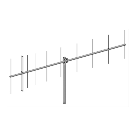
M2 Antenna Systems 222 HO LOOP User manual

M2 Antenna Systems

M2 Antenna Systems 222 HO LOOP User manual

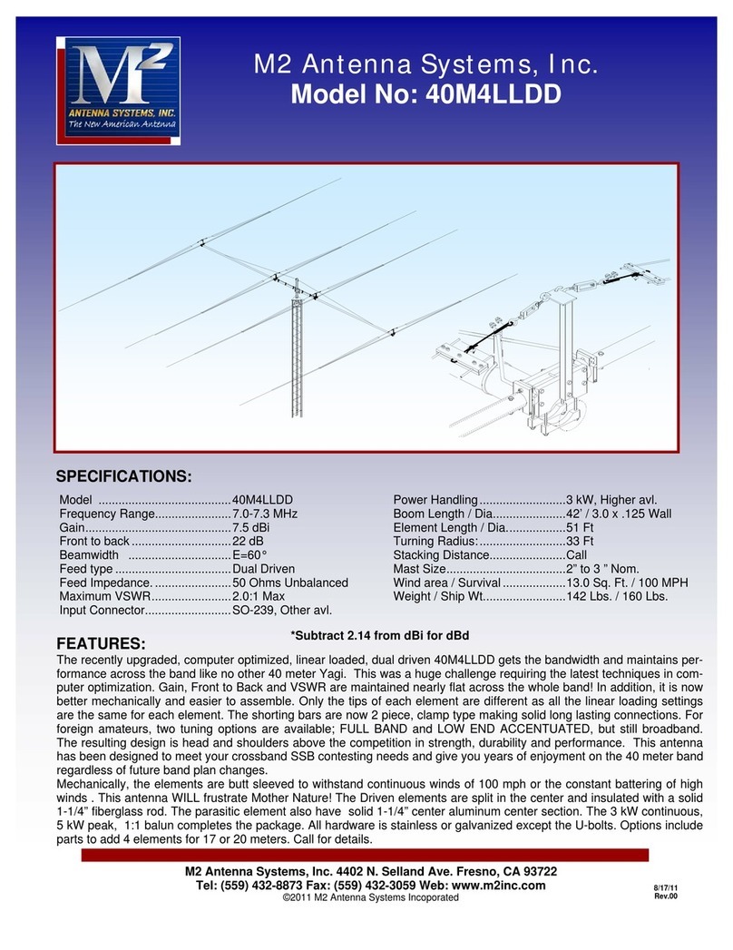
M2 Antenna Systems 40M4LLDD User manual

M2 Antenna Systems

M2 Antenna Systems 40M4LLDD User manual

M2 Antenna Systems 303CP26 User manual

M2 Antenna Systems

M2 Antenna Systems 303CP26 User manual

M2 Antenna Systems 2.4-18R User manual

M2 Antenna Systems

M2 Antenna Systems 2.4-18R User manual

M2 Antenna Systems 2MXP20 User manual

M2 Antenna Systems

M2 Antenna Systems 2MXP20 User manual

M2 Antenna Systems 11M5DX User manual

M2 Antenna Systems

M2 Antenna Systems 11M5DX User manual

M2 Antenna Systems 20M4DX User manual

M2 Antenna Systems

M2 Antenna Systems 20M4DX User manual

M2 Antenna Systems 500-1000-10 User manual

M2 Antenna Systems

M2 Antenna Systems 500-1000-10 User manual

M2 Antenna Systems FG170-230-5 User manual

M2 Antenna Systems

M2 Antenna Systems FG170-230-5 User manual

M2 Antenna Systems 40M3FS User manual

M2 Antenna Systems

M2 Antenna Systems 40M3FS User manual

M2 Antenna Systems 440-460-11HD User manual

M2 Antenna Systems

M2 Antenna Systems 440-460-11HD User manual

M2 Antenna Systems 436CP30 User manual

M2 Antenna Systems

M2 Antenna Systems 436CP30 User manual

M2 Antenna Systems 915XBISP User manual

M2 Antenna Systems

M2 Antenna Systems 915XBISP User manual

M2 Antenna Systems 2M18 series User manual

M2 Antenna Systems

M2 Antenna Systems 2M18 series User manual

M2 Antenna Systems 80M1L User manual

M2 Antenna Systems

M2 Antenna Systems 80M1L User manual

M2 Antenna Systems 23CM22EZB User manual

M2 Antenna Systems

M2 Antenna Systems 23CM22EZB User manual

M2 Antenna Systems 7-10-30LP8 User manual

M2 Antenna Systems

M2 Antenna Systems 7-10-30LP8 User manual

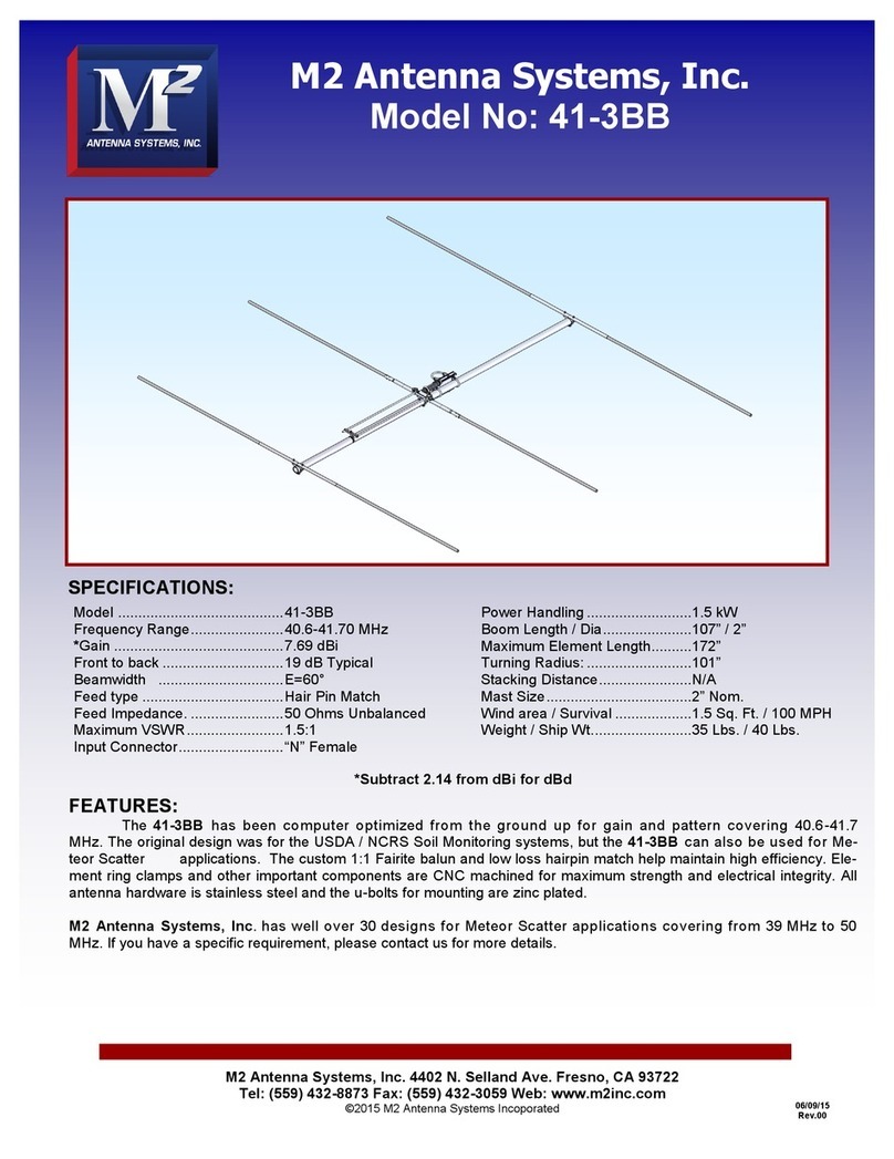
M2 Antenna Systems 41-3BB User manual

M2 Antenna Systems

M2 Antenna Systems 41-3BB User manual

M2 Antenna Systems 420-450-11HP User manual
M2 Antenna Systems

M2 Antenna Systems 420-450-11HP User manual

M2 Antenna Systems 10M4DX User manual

M2 Antenna Systems

M2 Antenna Systems 10M4DX User manual

M2 Antenna Systems 249CP24 User manual

M2 Antenna Systems

M2 Antenna Systems 249CP24 User manual

M2 Antenna Systems EB-144/RK2M User manual

M2 Antenna Systems

M2 Antenna Systems EB-144/RK2M User manual

M2 Antenna Systems 440-18 User manual

M2 Antenna Systems

M2 Antenna Systems 440-18 User manual

M2 Antenna Systems 40M1L User manual

M2 Antenna Systems

M2 Antenna Systems 40M1L User manual

Popular Antenna manuals by other brands

KVH Industries TracPhone V11 hts user guide

KVH Industries

KVH Industries TracPhone V11 hts user guide

Conrad DA-8300 operating instructions

Conrad

Conrad DA-8300 operating instructions

Nice AB Instructions For Fitting

Nice

Nice AB Instructions For Fitting

Dawnco P37F installation manual

Dawnco

Dawnco P37F installation manual

Mercury MAWB-A26 user manual

Mercury

Mercury MAWB-A26 user manual

Shakespeare Electronic Style 393 installation instructions

Shakespeare Electronic

Shakespeare Electronic Style 393 installation instructions

Goobay DVB-T DOA 50 PS instruction manual

Goobay

Goobay DVB-T DOA 50 PS instruction manual

Raven 600S Installation and operation manual

Raven

Raven 600S Installation and operation manual

cahors MINISAT user manual

cahors

cahors MINISAT user manual

Yaesu G-5400 quick start guide

Yaesu

Yaesu G-5400 quick start guide

Poynting EPOYNT-4 user guide

Poynting

Poynting EPOYNT-4 user guide

RCA ANT850E1 installation guide

RCA

RCA ANT850E1 installation guide

Naval PR-422CA Operation manual

Naval

Naval PR-422CA Operation manual

Ramsey Electronics DAP25 Kit assembly and instruction manual

Ramsey Electronics

Ramsey Electronics DAP25 Kit assembly and instruction manual

Winegard dish Playmaker instruction manual

Winegard

Winegard dish Playmaker instruction manual

YooFab RFLEGO Assembly instructions

YooFab

YooFab RFLEGO Assembly instructions

EchoStar DISH 500+ installation instructions

EchoStar

EchoStar DISH 500+ installation instructions

Honeywell HRA 80 Mounting instructions

Honeywell

Honeywell HRA 80 Mounting instructions

manuals.online logo
manuals.online logoBrands
  • About & Mission
  • Contact us
  • Privacy Policy
  • Terms and Conditions

Copyright 2025 Manuals.Online. All Rights Reserved.