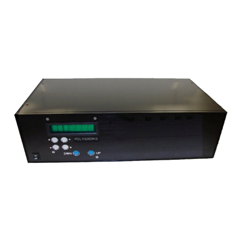
M2 Antenna Systems RC2800PX-AZ User manual


TABLE OF CONTENTS 4-23-03 REV 7-22-03
COVER PAGE
TABLE OF CONTENTS 2
FEATURES 3
GETTING STARTED 4
FRONT PANEL CONTROLS 5
RUN MODES 6
PROGRAMMING MODES & CALIBRATION 7,8
PROGRAMMING PRESETS 9
REAR PANEL AND INSTALLATION HINTS 10
OPERATION BY COMPUTER 11
AZ AND EL OPERATION BY COMPUTER 12
WRITING CONTROL SOFTWARE 13,14
TROUBLE SHOOTING 15,16
SIMPLIFIED THEORY OF OPERATION 17
WIRING AND PARTIAL PCB SCHEMATIC 18
WARRANTY 19

4-23-03
4402 N. Selland Ave, Fresno CA 93722 (559) 432-8873 FAX 432-3059
FEATURES
Our ALL NEW, GREEN LED, PIC rotator controller is packed with new features including
AUTO-CALIBRATE, AUTO SLOW DOWN as limits are approached, ONE STEP PRO-
GRAMMING saving all changes by exiting the program mode. SOFTWARE UPDATES di-
rectly from our “m2inc.com” website Also included is increased circuitry and reed switch
protection. Of course computer control has also been improved. The new RC-2800PX
now accepts fractional inputs like 138.7 degrees and the Auto-calibrate command from a
computer or remote site. What we did not change is front and back panel layout so it
doesn’t require re-learning the controls and the actual operation is almost identical to the
old units. Everything is just a bit smoother and easier. The new PIC microprocessor lends
itself to easier custom programming for special rotator control functions. This custom pro-
gram can be downloaded directly through the RS-232 port on your RC-2800PX from our
site on the WEB. Of course this new controller works with any of our older OR-2800DC ro-
tators. It can also be easily modified to work with MOST of our older AC (OR-2800AC)
units as well. By ordering an RC-2800PPX controller this design can control a Prop Pitch
Rotator with all the same features. If you have a very custom rotator system using a large
AC or DC motor of almost any voltage or phase (like 3 phase 240 AC) the RC-2800PX
design can control your rotator system. This same controller also controls our line of Ele-
vation rotators (Positioners) like the MT-1000, MT-3000, MT-4000 and the largest, MT-
5000. The Elevation controller can be linked to the AZ controller and both then can be
controlled by computer through a single RS-232 line. We also have a Dual controller (RC-
2800PRKX) in one rack mount case to control an AZ-EL system. The new RC-2800PX
controller it can handle any gear ratio from 1000 to over 50,000:1
Our OR-2800DC rotator is now supplied with a 60” PIGTAIL and a WATER TIGHT
HOUSING for a terminal strip. This creates an easy access, trouble free control cable
connection. Your control cable can have as few as 2 motor wires (see the “size VS dis-
tance” information later in manual) and a small single shielded lead for the position feed-
back.
3

GETTING STARTED (with an OR2800 azimuth rotator)
We highly recommend that upon receiving the rotator and controller, you hook it up in the shack
and get used to the operation.
Here is what you do.
1. Connect the black lead in the rotator pigtail to terminal #1 on the back of the control box.
2. Connect the White wire to terminal #2. (AND ON AC UNITS, connect the RED wire to #3).
3. Connect the Orange wire to terminal #5.
4. Connect the Blue wire to terminal #6.
5. Unwrap the AC power cord and plug in the RC-2800PX controller.
6. Turn on the controller. The NEW green display should come up and read “0” “9” XXX .X
7. Push and hold in the UPPER mode button. “P20 0.0” should come up.
8. Bump the LOWER mode button SEVEN (7) times until you see “P0 CAL”
9. Push in the LOWER mode button and you will see the SEGMENTS of the digit to the left of
the “C” start to rotate counterclockwise at the same time the rotator is moving Counterclockwise
(CCW). Release the LOWER mode button and the rotator will continue going CCW by itself at
half speed. Soon the rotator will stop and the display will change to read “0 9 L346”. The rotator
and the control box are now in sync and CALIBRATED. THIS PROCEDURE CAN BE RE-
PEATED ANYTIME IF YOUR CALIBRATION IS LOST, CHANGED OR SUSPECT. It can also be
done remotely from a computer. Normally, the only thing that can keep your RC-2800PX from
displaying the correct heading is IF your mast or antenna has slipped.
10. Now push the CW button and rotate the OR-2800 until the display reads 0.00 or close.
This represents TRUE NORTH, not MAGNETIC NORTH. The “antenna system” if one were
clamped to the top plate, should be pointed at TRUE NORTH and the mast clamps tightened.
YOU ARE NOW CALIBRATED. You should use the above procedure for your final setup too.
NOTE: Any known direction can be chosen for use in aligning the antenna to but you must run
the rotator to THAT heading PRIOR TO clamping the antenna in that direction. THAT’S IT. All
that is left to do is mount the rotator in the tower and connect up the control cable at both ends.
Clamp the antenna at the chosen heading as viewed on your RC-2800PX display and you are up
and running. More details on programming, presets, “South stop”, RS-232 interface, cable size
and possible shielding requirements and much more are on subsequent pages of this manual.
4

FRONT PANEL CONTROLS
“PWR” ROCKER SWITCH
Located in the lower left hand corner of
the front panel, this button controls AC
power to the unit.
DIGITAL DISPLAY
The digital display panel shows (from left
to right): MODE, SPEED, and
HEADING / PROGRAMMING data.
Display Digit:
#1: (full left): shows the selected MODE for operation or programming.
#2: Indicates the positioner travel SPEED in relative numbers from 0 to 9.
#3, Indicates, an ”L” for a Limit zone or a digit when programming in a high gear ratio.
#4, 5, 6, 7: Indicates HEADINGS, Azimuth or Elevation, in degrees and programming
data.
MODE BUTTONS
The Mode buttons are used to cycle through and select among 3 operational or "RUN"
modes, and 17 "PROGRAM" mode positions. See RUN MODES and PROGRAM
MODE details following this section.
“SPEED” BUTTONS
The speed buttons control the positioner's rate of speed in relative increments. "1" is
the slowest speed, "9" is the fastest. ‘0’ IS DISPLAYED WHEN THE ROTATOR IS
NOT MOVING. The top button increases the speed, the lower button decreases speed.
Lowest speed available DEFAULTS TO 1 but can be set to any number between 1 and
9 in program mode P5. Speeds can be altered for travel in any of the run modes, but
must be returned to speed 9 for full speed and full ramp functions.
“CW" (“UP”) and "CCW” (“DOWN“) BUTTONS
The "CW" and "CCW" buttons activate the positioner directly in Mode 0, Mode 1 and
Mode 2. These buttons also are used in the PROGRAMMING MODE to make
changes to factory defaults and for selecting preset headings.
NOTE: Throughout this manual you will see different words for the same item. Some
common terms would be: Sometimes we just get tired saying the same old thing.
RC-2800PX = Controller, Control box, box or unit.
DISPLAY = Readout, Heading,
ROTATOR = Positioner, Rotor
. 4-23-03
5

RUN MODE DESCRIPTIONS AND EXPLANATIONS
RUN MODES: Modes 0, 1, AND 2 are RUN modes that activate the positioner with manual or pre-
set commands. Momentarily push either MODE button to cycle through Modes 0, 1, and 2.
MODE 0: Manual operation mode. Pushing the CCW or DOWN button activates the rotator in the
COUNTER-CLOCKWISE direction and the HEADING count will go down. Pushing the CW or
UP button activates the rotator in the CLOCKWISE or UP direction and the HEADING count
will go up. The positioner runs while "CCW" or "CW" button is depressed, ramping up from
minimum programmed speed to the maximum (9) and stopping, WITHOUT ramp down, when
the button is released. When reversing direction there is a 2-3 second delay before posi-
tioner activation. This delay reduces stress on your antennas, tower and guy system.
NOTE:
Rotation direction, i.e., CW / UP or CCW / DOWN is defined as if you are looking down on
the rotator / antenna from above. There is no automatic speed ramp down when operating
in Mode 0 EXCEPT AS YOU APPROACH A LIMIT. Small movements of positioner may not
allow full speed to be reached.
(Special programming will soon be available at our web site (www.m2inc.com) that can be
downloaded directly into your RC-2800PX to reduce the ’reverse delay’ to .1 sec for special
applications). General updating will be available from the web site as well.
MODE 1: Computer control or Manual preset mode. When computer control is activated, a “1”
automatically appears in the MODE # location on the display. Manually the "CW" / UP and
"CCW" / DOWN buttons can be used to select a heading on the display from the full range of
rotation. AFTER the button is released, there is a short delay before positioner activation, al-
lowing time to adjust or "bump" your selection. As the positioner begins to run, the speed
ramps up from the minimum programmed speed to the maximum. As the target heading is
approached, the speed ramps down to stop. The positioner may then "bump" several times
until within about .5 degrees of preset. To STOP or cancel a preset ANY TIME, TOUCH ei-
ther mode button.
MODE 2: Programmable preset mode. Press the "CW" / UP and "CCW" / DOWN buttons to cycle
through 10 PRESET headings you program into Modes 20-29. Heading selections are shown on
display. After a short pause, allowing you to confirm you selection, the positioner will proceed to the
displayed heading the same as in MODE #1. Typically, these presets are programmed for frequently
used headings and / or stow positions for parking or extreme weather. TO STOP OR CANCEL A
PRESET IN MID TRAVEL TOUCH EITHER MODE BUTTON.
6

PROGRAM MODE DEFINITIONS AND EXPLANATIONS
PROGRAM MODES: Modes P1-P6 are PROGRAM modes that permit entering, changing, or re-
viewing programmed system parameters. PROGRAM modes P20 through P29 are reserved for
10 preset headings.
TO CYCLE THROUGH THE VARIOUS PROGRAMMABLE MODES, depress and hold the
UPPER mode button in for 3-5 seconds. The display will change automatically to mode P20. P20
is the first of your 10 PRESET headings. More on these later. Bump the LOWER mode button
down through modes P6, P5, P4, P3, P2, P1, AND P0 CAL. Go back up by bumping the UPPER
mode button. The display will show current mode setting. The FACTORY DEFAULTS are listed
below. Most of the time these will never be changed. To program or change any setting, depress
the "CW" / UP or "CCW" / DOWN buttons until the desired setting is displayed. Change anything
or everything in the program mode except P6 and SAVE just once. NOTE: THIS IS DIFFERENT
FROM OLDER VERSIONS OF RC-2800’s. ( NOTE: DURING PROGRAMMING, THE NUMBERS
CHANGE SLOWLY AT FIRST THEN SPEED UP. RELEASING THE BUTTON AND PRESSING
IT AGAIN RESETS THE PROCESS OF SLOW TO FAST NUMBER CHANGE )
TO ENTER “PROGRAM MODE“: Press and hold the upper Mode button until P20 appears.
P20 through P29 contain preset headings. We put in our favorites but you can choose
your 10 favorite directions or presets and change the default settings anytime. One or all
can be changed and then saved as described below.
Bump the lower mode button once and Mode P6 appears. For use with the OR2800 P6 is used
only to correct your heading if the antenna system was not clamped perfectly at the time
of installation or if your mast or antenna slips slightly in a high wind.. To change to a new
heading. touch the CW button. 0.0 should appear. Touch CW again. If the digits count up
( .1, .2 .3 etc.) continue until you near the corrected heading. Let off and press again. IF THE
NUMBER WON’T GO UP, WHEN CW IS PRESSED, then press the CCW button and proceed
until you approach the corrected heading. Let up and press again. If you overshoot, press the
other button until you get to the corrected heading. SAVE by pressing and holding the LOWER
MODE BUTTON until MODE 0 appears along with the current speed setting and your new, cor-
rected heading; example ( 0 8 23.5).
PROGRAM MODES, P5, P4, P3, P2, AND P1. THE DEFAULTS ARE SHOWN.
TO SAVE ANY OR ALL NEW PROGRAMMED SETTINGS AT THE SAME TIME EXCEPT FOR
P6: Depress the lower mode button UNTIL MODE 0 APPEARS. P6 must be saved as soon as it
is set.
P5 = 1This is the minimum SPEED and RAMP setting. A ‘1’ gives you full speed and ramp con-
trol. (NOTE: When trouble shooting a faulty operation, to get good motor voltage and reed switch
readings, it is helpful to temporarily set the speed to 9. This eliminates motor pulses and give a
steady DC reading for your DVM.)
P4 = 3960 This is the number of pulses from an OR-2800DC or AC for 360 degrees of rotation.
This number can also relate to the gear ratio of your rotator. Two pulses are formed for each mo-
tor rotation so your OR-2800 gear ratio is 1930:1. If you use an OR-2800 to turn your tower, and
you use a 2:1 step down for more torque, your mode P4 number would have to be changed to 2 x
3960 or 7290. ( the internal limit switches in the OR-2800 would have to be de-activated by re-
moving the limit arm inside the rotator). The RC-2800PX can handle pulse counts or gear ratios
of up to 40,000! The more pulse counts, the more accurate the rotation control and read- 7

out becomes. See the “Getting started” section for setup of other types of motor /
gear systems like prop pitch rotators or MT’000 series elevation mechanisms.
P3 = ‘0’ This is ‘NORTH STOP‘. North is 0.0 or 360 degrees. To set up for south or 180
degree stop, push CW / UP button till display reads ‘180’. Your CW default limit would
read L194 and the CCW limit would be L166. Any ‘STOP’ direction can be put in and
would change your CW and CCW limit readings accordingly. Not used for elevation
mechanisms.
P2 = ‘L14’ This is the CW limit that matches the physical limit switches inside the OR-
2800. The L14 would change automatically to ‘L194’ if you had set your RC-2800PX up
for SOUTH stop. See “Getting Started” section for MT’000 elevation mechanisms.
P1 = ‘14’ This is the CCW limit that matches the physical limit switches inside the OR-
2800. The ‘14’ would change automatically to ‘166’ if you had set your RC-2800PX for
SOUTH stop in P3. In actual operation, as your rotate CCW below 00.0 degrees or below
180.0 degrees, the display will show an ‘L’ before the true heading. When you turn the
unit on after a few days or even a few hours it is helpful to know you are in a limit zone
and can’t go much further in that direction. See “Getting Started” section for MT’000 ele-
vation mechanisms.
TO CALIBRATE YOUR OR-2800 CORRECTLY:
Push and hold in the UPPER mode button. “P20 0.0” should come up. Bump the
LOWER mode button SEVEN (7) times until you see “P0 CAL” Push in the LOWER
mode button and you will see the SEGMENTS of the digit to the left of the “C” start to ro-
tate counterclockwise at the same time the rotator is moving Counterclockwise (CCW).
Release the LOWER mode button and the rotator will continue going CCW by itself at
half speed. Soon the rotator will stop and the display will change to read “0 9 L346”. The
rotator and the control box are now IN SYNC and
CALIBRATED. THIS PROCEDURE CAN BE REPEATED ANYTIME IF YOUR CALIBRA-
TION IS LOST, CHANGED OR SUSPECT. It can also be done remotely from a com-
puter. Normally, the only thing that can keep your RC-2800PX from displaying the correct
heading is IF your mast or antenna has slipped.
Now push the CW button and rotate the OR-2800 until the display reads TRUE NORTH
(0.00) or close. The “antenna system” should be pointed at TRUE NORTH and clamped
using the OR-2800 mast clamps. YOU ARE NOW CALIBRATED
TO CALIBRATE YOUR MT1000, MT3000 OR MT5000 CORRECTLY: This part as-
sumes you have already set P4 to the proper gear ratio for your unit.
Press and hold the upper mode button until P20 appears. Bump the Lower mode button
once down to P6. Your 00.0 degrees of elevation can be set anywhere on the MT1000
since it can rotate continuously through 360 degrees. Run the display count down to 0.1
and save by pressing and holding the lower mode button until 0 9 00.0 appears. The
speed digit may be different.
MT3000 and MT5000 units typically set the array at 0 degrees as the array is “looking at”
the motor. This is very near one end of the chain on the D ring. Again in mode P6, use
the UP / DOWN buttons to set the display to 00.1 and save by pressing and holding the
lower mode button until 0 9 00.0 appears. The speed digit may be different.
8

PRESET MODE DESCRIPTION AND EXPLANATION
MODE P20-P29 = Reserved for entering 10 programmable ‘PRESET’ headings.
TO PROGRAM YOUR FAVORITE HEADINGS NOW, CONTINUE WITH THIS STEP
OR DO IT LATER.
TO PUT YOUR FAVORITE HEADINGS IN NOW , DO THE FOLLOWING:
PUSH AND HOLD THE UPPER MODE BUTTON. “P20 10.0” WILL APPEAR UNLESS
THE UNIT HAS A PRESET NUMBER ALREADY IN P20. NO MATTER WHAT AP-
PEARS, PUSH THE CW OR CCW BUTTON AND HOLD UNTIL YOU GET NEAR YOUR
FIRST FAVORITE HEADING; SAY IT’S 30.0 RELEASE THE BUTTON AND THEN
PUSH EITHER CW OR CCW TO GET TO EXACTLY 30.0 DEGREES. (NOTE THE NUM-
BERS CHANGE SLOWLY AT FIRST THEN SPEED UP.}
NOW BUMP THE UPPER MODE BUTTON AGAIN AND ”P21 00.0 SHOULD APPEAR.
PROGRAM AS BEFORE TO YOUR NEXT CHOICE.
CONTINUE UNTIL ALL 10 PRESET POSITIONS ARE FILLED.
NOW SAVE YOUR SETTING BY PRESSING AND HOLDING THE LOWER MODE BUT-
TON UNTIL MODE ‘0’ APPEARS.
YOU CAN CHANGE ANY OF THESE SETTINGS ANYTIME BY GOING BACK INTO THE
PROGRAM MODE, BUMPING UP TO THE “P” NUMBER YOU WANT TO CHANGE.
THEN CHANGE THE READOUT TO THE NEW HEADING. IT WILL BE SAVE WHEN
YOU EXIT THE PROGRAM MODE BY PRESSING AND HOLDING THE LOWER MODE
BUTTON UNTIL MODE ‘0’ APPEARS.
9

REAR PANEL
TERMINAL STRIP
This 6 terminal strip at left serves as cable interface to
the rotator unit. The cable supplies power to and data
from the rotator. Your multi-conductor cable from the
rotator connects here. A ground stud is provided at right
end of terminal for shielded cables. DISCONNECT AC
POWER CORD WHEN CONNECTING CABLE LEADS.
“RS232”
This is a 9 pin female (DB9) connector for linking to
computer RS232 port.
“VAC SELECT”
A flush mounted voltage selection switch for 115 or 230 VAC. At the factory, we set this switch to “115”.
“FUSE”
Provides electrical protection to components. Replace with a 3 Amp / 250V type. Units designed for use with
special or prop-pitch motors may require a different fuse , usually a 5 amp. Match factory installed fuse. A sec-
ond high current fuse may be present on some units controlling large prop pitch and 1/3 hp and up motors.
“AC IN”
The AC cord plugs in here. Connect to a reliable 115 VAC or 230 VAC source. Power is filtered to protect com-
ponents. TERMINAL ASSIGNMENTS
TERMINAL FUNCTION RECOM. COLOR MIN WIRE GAGE
#1 MOTOR BLACK AWG 16
#2 MOTOR WHITE AWG 16
#3 * 3 WIRE MOTOR ONLY RED AWG 16
#4 NOT USED
#5 REED SW. DC+ ORANGE AWG 24
#6 REED RETURN BLUE AWG 24
STUD CASE GND BARE NA
* THREE WIRE MOTORS INCLUDE: AC AND PROP PITCH MOTORS.
TERMINAL # 1 BECOME MOTOR COMMON. FOR OR2800DC, USE ONLY TERM. 1 AND 2.
INSTALLATION HINTS: Poor quality wiring or cable AND wiring errors are the major cause of opera-
tional failure. Occasionally this even causes rotator or control box failure.
For short runs of 100 feet or less, the wire sizes listed above are adequate. For runs over 100 feet, multi
conductor cable like Belden 9405 is fine. Since only four total conductors are required, and only two of
those conductors carry any current, 3 wires can be put in parallel for each motor lead. The danger here is
that you mix up the wire colors from one end to the other. Results can be disastrous so be very careful with
this paralleling technique. Sometimes so much capacitance exists in between the cable wires in long runs
that the nice SQUARE WAVE pulses formed by the reed switch and rotating magnets at the motor are dis-
torted and contaminated to the point that the microprocessor cannot count them accurately. A very positive
FIX for this condition is to use a shielded wire for the pulse / reed switch line. RG58 is great for this appli-
cation. It is made for outdoor use and it is reasonably rugged and tough and can withstand abuse and still
get the job done. If you want the KILLER CABLE for all applications, the WIREMAN makes an 8 conductor
plus one shielded conductor that will operate your OR2800 AC or DC reliably from over 850 feet from the
RC-2800PX. It is about the size of RG-213. We highly recommend it for those LOOONG runs! Another way
to handle a long run is to use two large #8 wires and a run of RG58. Run this way to the base of the tower
and then convert to Belden 9405 or Wireman cable for up the tower to the rotator.
10

OPERATION BY COMPUTER
1. Connect appropriate cable from your computer to Control Unit's DB9 connector on rear panel.
2. Most computers have a ‘HYPER TERMINAL’ or equivalent capability. T o get into Hyper terminal click
on your computers ‘Start’ box and go to ‘Programs’. Then slide to ‘Accessories’ and then to
‘Communications’
Then slide over to “Hyper Terminal”
Double click on Hypertrm.exe (execute file)
The next screen is called “Connection Description”
It will ask you to enter a ‘Name’ (ie OR2800P) and choose and icon. Then click ‘OK’
The next screen says “Connect to”. Go to the last box and click on “Connect Using”. Choose direct to
‘Com 1’ and click ’OK’
The next screen will bring up your Port Settings as follows:
baud rate 9600
bits 8
stop bits 1
parity none
handshake present, but not used
Click ‘OK’ and your terminal is now set up and accessible from your desk top icon.
If computer control is desired and a program like NOVA or SKYMOON is used, their instructions cover
the interface to the RC2800PX. Logging programs like CT and others are compatible as well. If you are
using a program that currently does not work with the RC-2800PX, send the author of that program a
copy of this page and the following two pages regarding writing software.
HYPER TERMINAL OPERATION:
A. Commands in upper or lower case are acceptable.
B. All commands are followed by an ENTER (carriage return / cr).
C. Remote operation (Mode 1) is initiated automatically from the terminal. Once terminal is at-
tached to the RC-2800PX, TURN ON THE RC-2800PX. IF IT HAS BEEN ON, TURN IT OFF.
WAIT 5 SECONDS, AND TURN IT BACK ON. Display will look something like this:
M2AZ1 2.2 KO6YD The 2.2 is the version software and KO6YD is the author.
A=25.4 S=9 SNote: early units may not have the decimal point. S = top
speed setting and ‘S’ means the unit is stopped.
D. To go to a new heading say 180.5, type that number in and hit ‘enter’. The readout will stream
down the monitor during rotation. It will look something like this:
A=26.7 S=1 M (‘M’ indicates the rotator is moving)
A=32.8 S=3 M
A=37.3 S=6 M
A=45.2 S=9 M
and finally;
A=180.6 S=9 S
If you turn the unit off, the last message would be: A=180.6 ERR=05. ERR=05 means the unit
has saved all volatile data and is experiencing “Low 12 volts”. Other ERR messages can be
found in the ‘SOFTWARE PROGRAMMING’ section.
E. You can now increment (0.5 deg orless) quickly back and forth with no delay. Type + and
‘enter’ for CW or UP and –and ‘enter’ for CCW or DOWN. This feature is currently Keyboard en-
try only.
11

USING RC-2800PX’s FOR DUAL CONTROL OF AZIMUTH AND ELEVATION POSITIONERS
3. The RC-2800PX Azimuth Controller circuit board has an additional port to interface with another
RC-2800PX for dual control of and MT series Elevation Positioner (Rotator). This is necessary if you
plan to control your antenna array in both the azimuth and elevation axes via a computer. If you have
purchased an M2MT-Series Elevation Rotator and wish to control it simultaneously with the RC-2800PX
Azimuth Controller the following steps must be made:
A. Contact us to order the MT-Series Jumper Cable or how to make one yourself (wired 1:1,
2:2, etc).
B. Remove the top covers of the azimuth and elevation RC-2800PX.
C. Attach the MT-Series Jumper Cable to the 10 pin socket labeled J41, with the RED STRIPE
DOWN, on the RC2800PX AZIMUTH Controller circuit board. J41 is located just right above the
RS232 Port cable. Now feed the jumper cable through the rectangular hole in the back plate of
the controller.
D. Next insert the jumper cable through the same square hole on the back side of the of the RC-
2800PX ELEVATION unit. Attach the jumper cable to the 10 pin socket labeled J41 on the circuit
board, with the RED STRIPE DOWN.
E. Bring up the desired control program (SKYMOON, NOVA or Hyper Terminal).
F. Turn on both units simultaneously or the AZIMUTH CONTROLLER first, then the ELEVA-
TION CONTROLLER.
G. SKYMOON AND NOVA operation is handled in those programs. When just using the Hyper
Terminal mode from the computer keyboard, you must select A or E and then type the desired
heading. The system will default to the ‘A’ (Azimuth) control when first turned on.
USING THE RC-2800PX-PRK (Rack mount dual controller)
The RC-2800PX-PRK contains two almost identical RC-2800PX printed circuit boards. The only differ-
ence is the Micro processor programming. The AZ chip is slightly different from the EL chip in that the
AZ chip controls the final data stream to and from the computer and sets up the time share between the
AZ and EL units. There is a 10 wire jumper between the two board running from J41 to J41. All opera-
tion is identical to the details described in the individual AZ and EL manuals.
SKYMOON AND NOVA operation is handled in those programs. When just using the Hyper Terminal
mode from the computer keyboard, you must select A or E and then type the desired heading. The sys-
tem will default to the ‘A’ (Azimuth) control when first turned on.
12

USE THE FOLLOWING INFORMATION TO WRITE YOUR OWN CONTROL SOFTWARE
SUMMARY OF CONTROLLER COMMANDS
Typed commands in lower or upper case, cr = ENTER or carriage return, # = real number including
tenths.
FUNCTION COMMAND DESCRIPTION
SELECT: Aor Ecr where A = Azimuth, E = Elevation
SPEED: S# cr where S = 1 (minimum speed) through 9 (maximum)
GO TO: #cr where # = a number within your programmed parameters. Num-
bers less than 1.0 must be preceded by a 0.#, (0.3)
INCREMENT +cr where + = bump + approximately .5 degree
DECREMENT -cr where -= bump -approximately .5 degree
STOP Scr where S = stop movement
UPDATE cr where cr gives one line of Position, Speed, and Movement Status
CALIBRATE CAL NA cr Where ‘cal” starts the positioner moving slowly CCW to
the physical limit switch in the positioner and then automatically resets readout to L346.0.
HOW THE COMMANDS WORK
The RC-2800PX is always in a continuous update mode.
A=135 S=5 M
Meaning: Selected controller (A or E) heading and other status is continually streaming down
the HYPER-TERMINAL screen while positioner is moving. Once (A) azimuth or (E) elevation is
selected, the A or E command is no longer needed. All commands that follow will affect only the
selected positioner.
TO SELECT AZIMUTH OR ELEVATION CONTROL
Type one of the commands below and follow with an ENTER (cr):
-for Azimuth, type: A
-for Elevation, type: E
Once azimuth or elevation is selected, the A or E command is no longer needed. All commands
that follow will affect only the selected positioner.
TO INCREASE OR DECREASE SPEED (assumes A or E has been entered)
Type the command and follow with an ENTER (cr). Speed changes may be entered while positioner is
stopped or moving.
-for minimum speed, type: S1
-for maximum speed, type: S9
Commands S1 through S9 are available. For instance, S4 will set speed to 40% of maximum. Posi-
tioner will return a confirmation with "S=4" and update status at time of command. For example, com-
mand "S8" might return:
E=60.5 S=8 S
Meaning: E (elevation mode), position = 180 degrees, S (speed)=8 (80%), S (stopped)
(or M -moving).
13

TO SELECT A POSTION (assumes A or E has been entered)
Type the command and follow with an ENTER (cr). Positions below 0 or above 360 degrees will cause the
display to flash:
-select recognized Azimuth and Elevation positions from within your programmed parameters.
Positioner will return a confirmation with "P=XXX" and update status. For example, the command "135"
might return:
A=135 S=5 M
Meaning: A (azimuth mode), to 135 degrees, S (speed)=5 (50%), M (moving).
RETURNED VALUES
All strings, including updates and error conditions, returned to the terminal by the controller are followed by
a line feed (OA) and a cr (OD). No echoes are returned.
ERROR CODES:
There are a number of error conditions, returned by the controller to the terminal, as shown below (assume
Azimuth):
A ERR=03
"Unexpected character" -returned when the received command is unknown.
A ERR=04
"Unexpected byte" -returned when the number of bytes received exceeds the buffer space.
A ERR=05
"Low 12 volts" -returned when the controller has detected a low 12 volt condition and has saved the current
position and speed in a non-volatile memory. If the positioner was moving when this condition occurred,
pulses counts could be lost, causing a slight error in the saved position.
14

RC-2800PX / OR2800 TROUBLE SHOOTING
SYMPTOM:
When rotator is wired to RG-2800PX, the rotator runs just for a second and then stops. And
‘E’ will appear in the mode column of the display. To reset, hit either mode key.
Why does this happen? Most commonly, The microprocessor will not let the motor run more than a
second if the micro’ sees no pulses coming in from the reed switch in the rotator. If the rotator
moves slightly, it means your motor and motor wires are probably OK.
POSSIBLE CAUSES:
This usually means that the RC2800PX is not getting pulses back from the rotator.
First remove the pulse wires from terminal 5 and 6 from the back of the control box.
Using a digital volt meter or equivalent, measure the voltage that is present between terminal 5 and
6 for about 1 second when you command the unit to go.. You should have 11.3 VDC. If this voltage
does not appear briefly, turn off the control box and measure the resistance between terminal 5 and
6. If the resistance is less than 5000 Ohms, it means the protective MOV across terminal 5 and 6 in-
side the box is leaky or shorted. If the MOV is damaged it means it took a voltage spike over about
25 volts. It failed but protected the internal circuitry. Unplug the box, remove the cover, and using
diagonal cutters, cut one lead of the red MOV soldered between terminal 5 and 6.
Now turn on the box and check for the 11.3 VDC between terminals 5 and 6. If the voltage is pres-
ent, turn off the box, replace the cover and reattach the wires to terminal 5 and 6. Turn on the box
and press CCW or CW to see if the rotator now operates properly. If so, got to “P0 CAL” and recali-
brate the unit as described at the beginning of this manual. Call M2 and order a new MOV. The sys-
tem can be operated without the MOV but during this time you have no voltage spike protection.
When all else fails, call M2 at 559 432 8873 and we will help you trouble shoot the system.
If the above appears OK, then the missing pulses maybe caused by a control cable problem
or a damaged. Again, turn off the box and remove the wires from terminal 5 and 6. Attach your me-
ter in the resistance mode across the two leads just removed. Two states can exist. Your reading will
either be a total open 10 meg Ohms or more OR a total short measuring only the resistance of the
wires running to the rotator. NOW with the meter leads still connected and measuring Ohms, turn
on the box and press CCW or CW and make the rotator move. Watch the meter to see the state of
the reed switch changes. Each motor revolution will open and close the reed switch twice so you
should see the meter change from open to shorted. This may take a few tries as the reed switch is
open normally about 60% of the time. If you see no change of state, you either are not on the reed
wires, or there is a break in the wires between the rotator and the box or you have a faulty reed
switch. The later is very unlikely. Most of the time this problem is due to a wiring or connection
problem somewhere between the rotator and the control box. Use common sense trouble
shooting your wiring.
SYMPTOM:
Rotator operates but readout is erratic or consistently reads higher or lower than where the
antenna system is actually pointing.
This is also an indication of wiring problem. Long runs of cable that have a cut in the jacket can fill
with water and significantly increase the inter-wire capacity. This can allow motor spikes to be
picked up by the pulse (reed switch lines) and add extra pulses to the count. It can also cause such
distortion of the square wave from the reed switch, that the microprocessor can’t read the actual
pulse count. Replace the cable or run a separate RG-58U or equivalent line for the reed switch.
This is not usually an indication that the reed switch itself is faulty. Don’t remove the rotator until you
are absolutely sure the problem is in the rotator. 4-23-03
15

TROUBLE SHOOTING CONTINUED.
SYMPTOM: Rotator runs immediately after control box is turned on: This can mean that one of
your motor control wires on terminal #1 or #2 is grounded. When one of your motor wires is
grounded it completes the path to one side of the power supply. The micro processor normally
turns on a Darlington that in turn turns on the Mosfet that closes the circuit to ground and powers
the motor.
To test this, remove the motor wire from terminals #1. Using your ohm meter, see if this wire is
shorted to ground. If not, then the problem may be in the control box. The mosfet could be shorted
or the Darlington could have failed allowing 10 volts of drive to appear on the gate of the mosfet,
turning it on all the time. To confirm that the box is faulty, remove the motor wires. Using your volt
meter, measure from terminal #1 to #2. 35 to 45 vdc will be present if the box is faulty. Call M2 for
an RA (Return Authorization) number so we can be ready for your unit when it arrives.
Send it to:
M2 Antenna Systems Inc.
4402 N. Selland Av
Fresno, CA 93722
We NOW INCLUDE a copy of the power supply and conditioning and the motor control schematic
if you prefer to do the repair . Here are some helpful details.
The Dual Darlington chip is an eight lead package SN75452 and may be available at local elec-
tronic parts stores in your area. Digikey and other large suppliers also would stock this device. The
mosfet is a IRFI 530 (International Rectifier, Insulated case) device and it can be crossed to sev-
eral devices with equivalent or higher voltage and current. The Dual Darlington is in a socket for
easy replacement. The mosfet is bolted to the chassis so the board must be removed to replace it.
Input from the micro to the Dual Darlington is pins 1 and 2 for motor control and the output is pin 3
When the unit is in standby, the input is high (5 vdc) and the output is low (under 1 vdc). When
and UP or DOWN button is pressed, the input goes low, allowing the output to go high (10 vdc)
driving the mosfet on and closing the circuit to ground on the motor.
The Dual Darlington also controls the motor direction relay. Input pins are 6 and 7, output is pin 5
so if your motor will not reverse, perhaps this half of the Dual Darlington is faulty.
16

SIMPLIFIED THEORY OF OPERATION
The positioner will not run if it receives no pulses back from the reed switch.
The system works like this: terminal #5 on the back panel is supplied voltage from the inter-
nal 12 VDC supply. This 12 volts passes through a 2.2k Ohm resistor and then through and
opto-isolator and out to terminal #5. The opto-isolator is basically an LED and An optical
pickup that isolates our system from the outside world of voltage spikes etc up to 2500
volts. The 11.3 vdc and the ground return runs through a DPDT relay K1, which when
closed, places the 11.3 and ground return on terminal 5 and 6 on the back of the box. Ter-
minal #6 is now only grounded when K1 is closed. (ONLY when the positioner has been ac-
tivated and is moving and pulses are still coming in). We did this to remove the ground po-
tential from the cable and thereby reduce the potential for lightning or nearby impulses to
find a path to ground in the cable. We feel this will further protect the reed switch circuit be-
yond the internal MOV and the opto-isolator.
When you ‘command’ the RC-2800PX to run the positioner in MODE ‘0‘ by pushing the CW
button, it knows to count up and by pushing the CCW button it knows to count down. The
command to count one way or the other comes from the buttons on the front panel.
When you ‘command’ the RC-2800PX to run the positioner, the internal ‘direction’ relay
opens or closes, the reed switch relay closes, and the microprocessor open its gate to any
pulses coming in on terminal #5. It also turns on a power mosfet that closes the motor cir-
cuit. It then pulses the motor on a few times and watches for some returning pulses. If no
pulses come back, the micro shuts down the mosfet which turns off the motor.
The 11.3 volt square wave pulses are formed when the reed switch closes and shorts the
11.3 V to ground ( remember the 2.2K Ohm resistor?). The 11.3 V drops to essentially
0 VDC. The internal magnets mounted on the motor shaft, rotate past the reed switch caus-
ing it to close and open and close and open as they swing by. There are two magnets on
the shaft and they go by the reed switch 3960 times in one OR-2800 rotation of 360 de-
grees. The gear ratio of the OR2800 is 1980:1. So two magnet pulses per rotation produce
3960 pulses per rotation.
Look in PROGRAM MODE #4 and you will find the number 3960. The microprocessor uses
this number to mathematically make sure your readout says 360.0 when you have gone
360.0 Amazing stuff eh? Now you see why we take such pains to have you make sure all
the pulses get back and get counted by the microprocessor.
FOR PROP PITCHES AND OTHER MOTOR GEAR BOXES
You can use the RC-2800PX to determine an unknown gear ratio. First program mode #4 to
10,000 and save it. Next use the RC2800PX to rotate the system exactly 360 degrees
physically. Now check the readout. It may say 280.0
Set up a ratio equation: 10000/280 = X/ 360. Cross multiply to get 280X = 360,0000. Solve
for X by essentially dividing both sides of the equation by 280 and you find the gear ratio (X)
is actually 12857:1 The RC-2800PX can now be re-programmed in MODE #4 from 10000
to 12857 and saved. Your readout will now be 360.0 for 360 degrees of rotation.
17

1. DC MOTOR LEAD
2. DC MOTOR LEAD
3. NOT USED
4. NOT USED
5. REED SWITCH +11VDC (PULSED WHEN RUNNING
6. REED SWITCH RETURN
TERMINAL STRIP WIRING
.
RC28WRAZ
M. STAAL
10-23-96
REV. 6-18-03
18
RC 2800PX PC BOARD SCHEMATIC PAGE 2
POWER CONDITIONING, MOTOR CONTROL
AND REED SWITCH PULSE CONDITIONING
C37
0.47uf
D33
1N4004
D33
1N4004
U36
SN75452
0.1uf Q30
IRFI 530N
R33
330 1/2W
DIRECTION/RELAY
MOTOR
R31
NI +
+5V
1
C36
0.1uf
+
23
7
-POS SW
U37A
74HC14
C30
NI
R37
4.7K
MTR 0N
DIR CH
+5V OPTIONAL
R30
NI
1
6
7
2
45
83
ON
R32
2.2K AC MOTOR DRIVER
SEN_EN
1
5
U38
4N26 +12V
2
R3
10K
3
1
Q1
2N2222
2N3904
+
x
2
6
4C39
0.1uf
TRIAC OPTION PARTS.
+12VDC
ON IS 10VDC
0FF IS .3VDC
CONTROL
T2500
Q31
1
R38
1.5K
C38
0.1uf
2
3
C31
1000uf
OR
6800uf
+12VDC REG.
C33 2
10uf
+5V
C35
+
+5V
+1
U31
LM7805
3
+C32 2
10uf
2200 uf
25V
+
18VAC-T1
2
3
1
BR30
1.5 AMP
4
+12V
+
3
U32
LM7812 +23VDC
1
MTR-ON/DC-DRV
7
6
THIS DOCUMENT CONTAINS INFORMATION PROPRIETARY TO
M2 ANTENNA SYSTEMS, INC. ANY REPRODUCTION DISCLOSURE OR
USE OF THIS DOCUMENT IS EXPRESSLY PROHIBITED EXCEPT AS
M2 ANTENNA SYSTEMS, INC. MAY OTHERWISE AGREE IN WRITING.
DECIMALS ANGLES FRACTIONS
DIMENSIONSAPPLYAFTERPLATING
REV 7-3-03
±1/16
1-9-03
K1
OMRON 65V-2
DPDT RELAY
DWN BY:
8
D3
1N4004
16
1
13
6
9
11
4
UNLESS OTHERWISE SPECIFIED DIMENSIONS ARE IN INCHES
±1/2
BREAK SHARP EDGES .02 MAX
FILLET R .005 MAX
.X
.XX
.XXX
±.03
±.015
±.005
DIMENSIONAL TOLERANCES
DATE:
M. STAAL
MOUNTS IN TOP
SET OF HOLES
JP31
FOR OFF-BRD
MOSFET
1
JP1
2
M ANTENNA SYSTEMS, INC.
4402 N. SELLAND AVE, FRESNO, CA 93722 559 432 8873
RC2800PX PC SCHEMATIC
PAGE 2
M2 P/N
M2 PART NUMBER:
PART NAME:
2
FILE NAME / REV.
NEWSKEM2
GROUND
12V_DC
DIR_CW
REED RETURN
REED-SW +11V
TB12X1
10
11
12
9
8
NC
K30
P&B RTE24012
DPDT RELAY
D34
1N4004
12
C29
4700 uf
50V
+
34VAC
4
2
3
1
+48VDC
GBU802
8 AMP
BR31
+12VDC
1
8
6
4
237
5
34VAC IN
34VAC IN
18VAC IN
18VAC IN
MTR-RTN/DC-DRV
1
2
3
4
5

This warranty gives you specific legal rights. You may also have other rights which will vary
from state to state or province to province.
M2 warrants the OR2800PX Positioner and RC2800PX Control unit against defects in
material and workmanship for a period of 12 months from date of purchase. During the war-
ranty period, M2 will, at its option, either repair or replace products or components which
prove to be defective. The warranty shall not apply to defects or damage resulting from:
•Improper or inadequate maintenance by user
•Improperly prepared installation site
•Unauthorized modifications or misuse
•Accident, abuse, or misapplication
•Normal wear
M2 specifically does not warrant this product for any direct, indirect, consequential, or
incidental damages arising form the use or inability to use the product. Some state or prov-
inces do not allow the exclusion or limitation of liability for consequential or incidental dam-
ages so the above limitation may not apply.
In the event repair or replacement are necessary, purchaser shall contact M2 for return
authorization. In many cases this contact can simplify and expedite the repair / replacement
process and help reduce costs and downtime.
The purchaser shall be responsible for packing the product properly for return and for
charges to ship the product to M2. Always include with the shipment, a statement detailing the
problem / failure and any other pertinent observations. Insuring the product for shipment is
recommended. Use the original packing materials whenever possible. M2 is responsible for
charges (in the United States) to return the repaired / replacement product only where war-
ranty service is involved.
19
and / or
Table of contents
Other M2 Antenna Systems Controllers manuals
Popular Controllers manuals by other brands

Riso
Riso IS300 Utility guide

Southwest Microwave
Southwest Microwave INTREPID Technical manual

SAMCHULLY
SAMCHULLY NeoCon Series instruction manual

Franke
Franke ZA3OP0034 Installation and operating instructions

Belimo
Belimo LF-2 Series Product information

Tornatech
Tornatech GPL Installation and maintenance manual

Niko
Niko 310-01800 manual

AMS
AMS XL200 Series Installation guide & technical reference

B&B Electronics
B&B Electronics RS-485 Digital I/O Module 485SDD16 user manual

NTI AG
NTI AG LinMot E1200 Series installation guide

Trane
Trane Tracer UC210 Installation, operation, and programming

Branson
Branson Emerson Ultrasplice 40 operating manual