M2I TOPRHWS User manual

TOPRHWS Hardware Manual
M2I Corporation
11-35, Simin-daero 327beon-gil, Dongan-gu, Anyang-si, Gyeonggi-do, 14055,Republic of Korea
1 / 19
Thank you for purchasing M2I TOPRHWS.
Please read this user manual carefully for safe installation, wiring, and operation of this equipment before
use.
TOPRHWS
TOPRHWS02
M2I Corporation
TOPRHWS / TOPRHWS02
Hardware Manual

TOPRHWS Hardware Manual
M2I Corporation
11-35, Simin-daero 327beon-gil, Dongan-gu, Anyang-si, Gyeonggi-do, 14055,Republic of Korea
2 / 19
Index
Index .................................................................................................................................................................................................................. 2
Chapter 1 Safety Precautions................................................................................................................................................................. 3
Chapter 2 Overview .................................................................................................................................................................................... 5
2.1 Product Introduction....................................................................................................................................................... 5
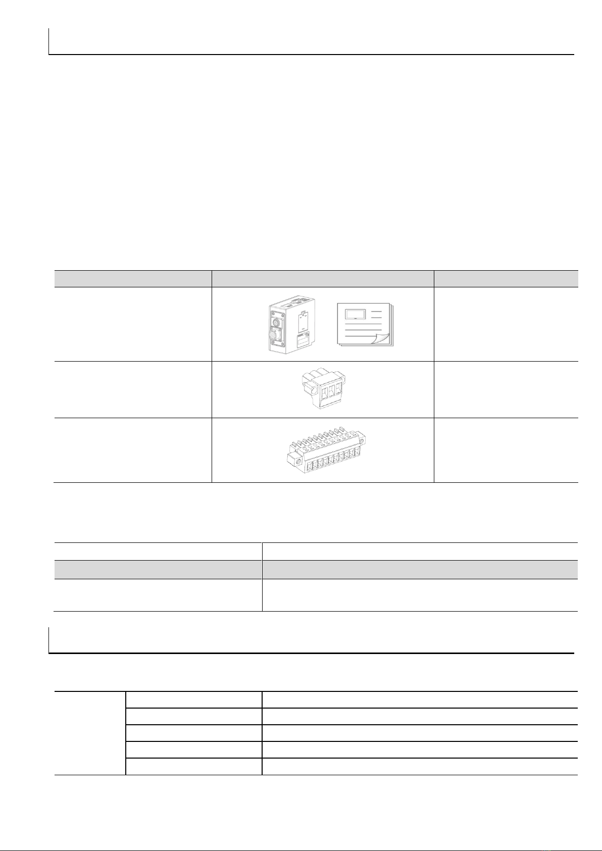
2.2 Components........................................................................................................................................................................ 5
2.3 Model Name Description ............................................................................................................................................. 5
Chapter 3 General Specifications ......................................................................................................................................................... 5
3.1 Power Specifications ....................................................................................................................................................... 5
3.2 Environment Specifications.......................................................................................................................................... 6
3.3 Structure Specifications ................................................................................................................................................. 6
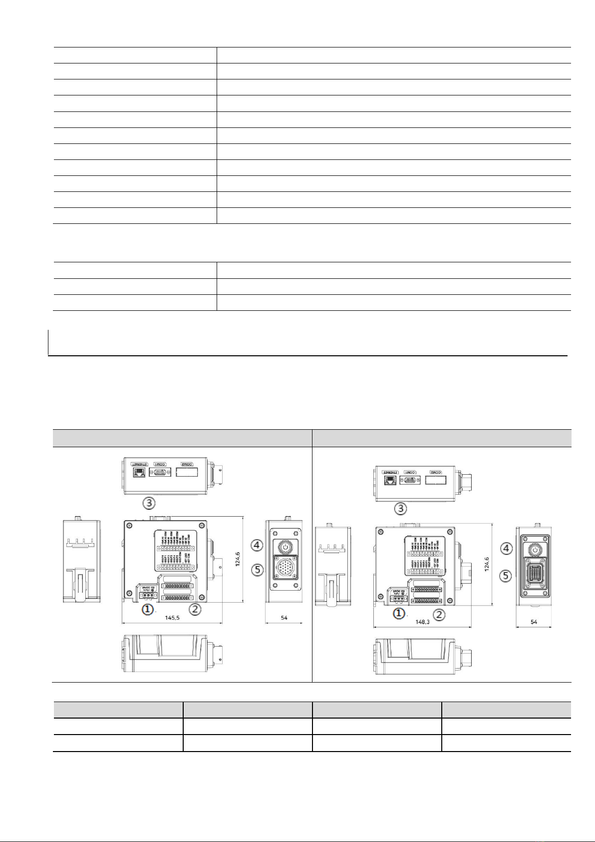
Chapter 4 Parts and Detail Specifications........................................................................................................................................ 6
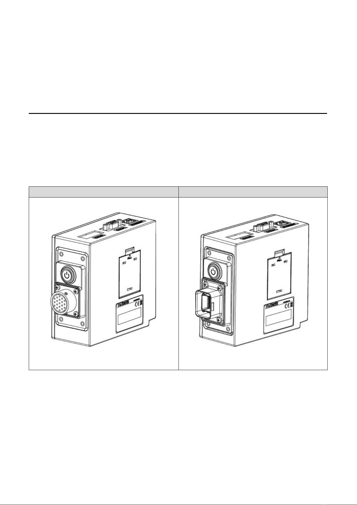
4.1 TOPRHWS Series............................................................................................................................................................... 6
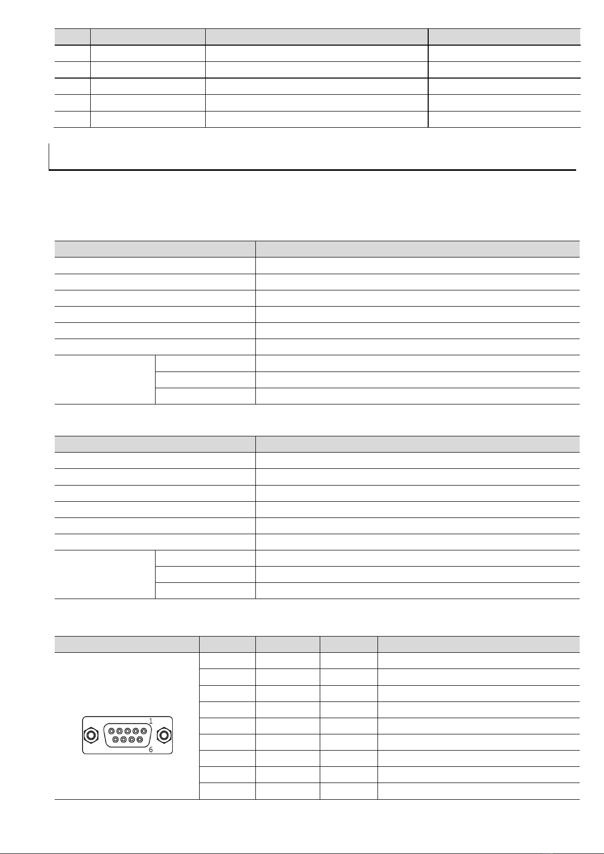
Chapter 5 Interface with Other Devices............................................................................................................................................ 7
5.1 Serial Communication Specifications ...................................................................................................................... 7
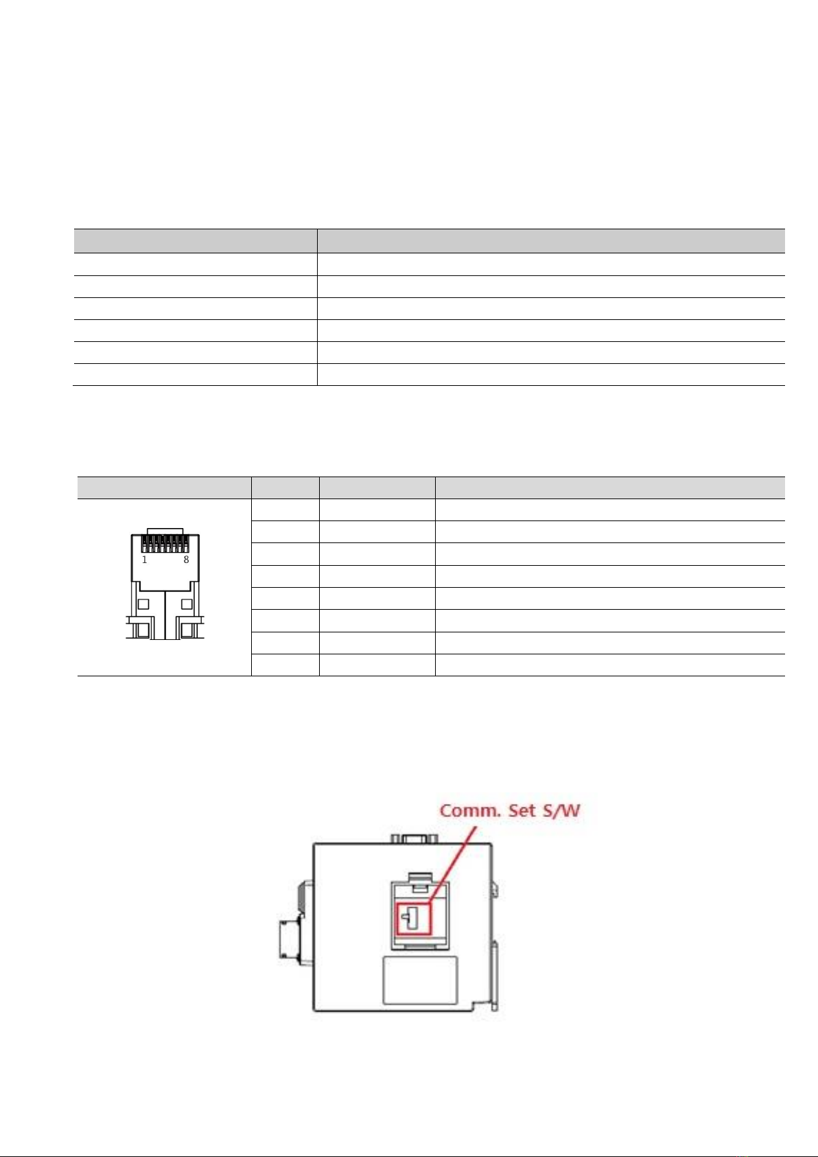
5.2 Ethernet Communication Specifications ................................................................................................................ 8
Chapter 6 Block Diagram for Installation......................................................................................................................................... 9
6.1 Connection Diagram....................................................................................................................................................... 9
6.2 Panel Cut Size for Front Panel Installation.........................................................................................................10
6.3 Cable Diagram .................................................................................................................................................................10
6.4 Mechanical Switch Setting of TOPRH0700WD FE Main Body ..................................................................13
6.5 Serial and Ethernet Communication Setting Switch......................................................................................13
6.6 The Purpose and examples of External Functions..........................................................................................13
Chapter 7 Installation and Wiring......................................................................................................................................................17
7.1 Selecting installation Location..................................................................................................................................17
7.2 Connection of the Cable Pack to the Main Body ...........................................................................................17
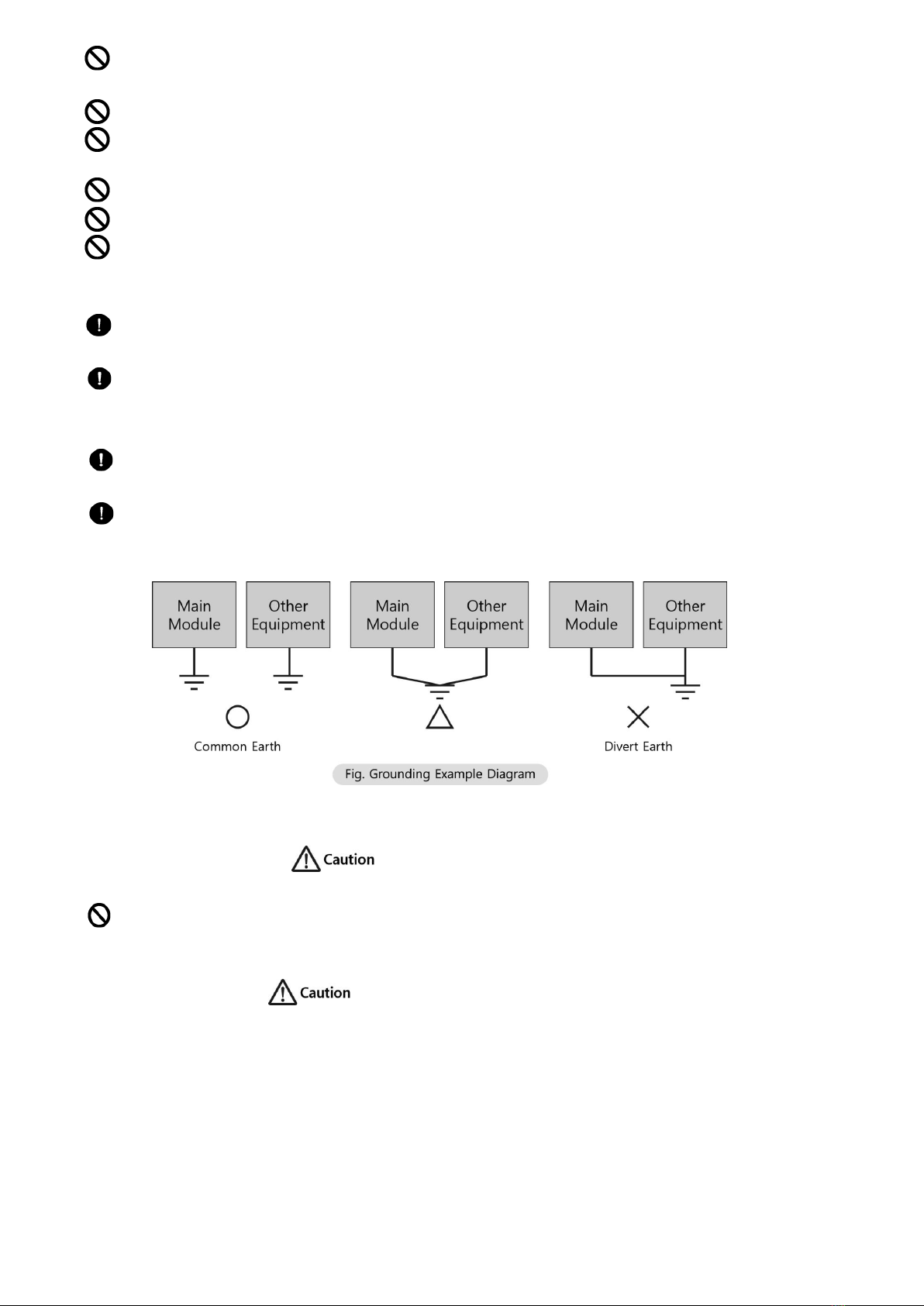
7.3 Power Wiring....................................................................................................................................................................17
Chapter 8 Maintenance ..........................................................................................................................................................................18
8.1 Surface Cleaning .............................................................................................................................................................18
8.2 Regular Inspection .........................................................................................................................................................18
8.3 Problems with the Product ........................................................................................................................................18
Chapter 9 Warning Label.......................................................................................................................................................................19
Chapter 10 Product Label......................................................................................................................................................................19

TOPRHWS Hardware Manual
M2I Corporation
11-35, Simin-daero 327beon-gil, Dongan-gu, Anyang-si, Gyeonggi-do, 14055,Republic of Korea
3 / 19
Chapter 1 Safety Precautions
■Before Use
For safe operation of the equipment, the user is required to read the contents of this manual thoroughly
before use. The safety precautions are for the safe and right use of the product. Therefore, please follow
the safety precaution so as to prevent accidents and potential dangers. They are classified into ‘warning’,
‘caution’ and each defined as follows.
Violating the instruction may result in serious personal injury or death.
Violating the instruction may result in slight personal injury or product damage.
Be cautious, there is a potential danger.
Be cautious, there is a possibility of an electric shock.
■General Precautions
Do not press the screen with a hard or sharp object (awl, screwdriver, pen, etc.) or apply excessive
force to it.
Do no use or store the product where high vibration can occur.
Do not allow foreign objects (e.g. water, liquids, metal powders) into the product.
This may cause breakage or electric shock.
Do not use a radio or mobile phone within a 30-cm radius from the main body.
A high-frequency radioactive device such as a mobile phone may cause a malfunction to the installation.
Do not store or operate in an environment exposed to sunlight.
Do not touch an adaptor or power code with wet hands. It can cause electric shock.
Do not use this product in explosive environments with flammable liquid, gas, or dust.
If the product needs long-term storage without using, avoid direct sunlight and keep dry condition.
After installation, normal operator should touch exposed area on front side.
■Design Precautions
In case that external power supply failure or a product error is suspected, please install a protection
circuit outside of the product.
As malfunction or/and an output failure of the product may pose a serious threat to the stability of
the entire system and a user, the product must be installed with the system physical damage
protection units including emergency stop switch, lower/higher limit switch, and interlock circuit for
forward/backward motion.
When a computer or other external controllers exchange data with the product or control the
operation (driving) mode of the main body of the product through communication, it is necessary to
set up interlock in the sequence program to protect system communication error.
Install output signal or communication lines at least 100mm (3.94 inches) away from a power line or
a high-tension wire.
■Installation Precautions
Do not install the product in temperature ranges out of allowable level. Otherwise, it can damage the
product or shorten its service life. Especially avoid the installation environments below.

TOPRHWS Hardware Manual
M2I Corporation
11-35, Simin-daero 327beon-gil, Dongan-gu, Anyang-si, Gyeonggi-do, 14055,Republic of Korea
4 / 19
Ambient temperatures lower than 0℃or higher than 50℃and/or on the surface of the control board
where a high-pressure device is installed.
Where it is continually exposed to an excessive impact or vibration.
The space between the rear of the main body and the console box should be at least 100mm for
maintenance and ventilation. Do not install a cooling fan in case of installation in a confined space.
Use it only indoors.
Use the product under 2000M altitute.
Power cable’s length should be less than 3 Meters (10ft).
■Wiring Precautions
Before wiring work, check the rated voltage for each component and its terminal layout and make
correct writing. Otherwise, it may cause a fire, electric shock, or/and malfunction.
Tighten the terminal screw with the specified torque. The loose screws of the terminal can be the
cause of short circuit, a fire, or/and malfunction. Use a standard earthing for FG terminal. When not
earthed, it can cause malfunction.
a. It should be triple earth and earthing point, as below, gets as close to the main body as possible and the earth
line should be as short as possible.
b. Earthing point, as below, gets as close to the main body as possible and the earth line should be as short as
possible.
■Operational Precautions
An excessive impact or force may deter the operation of the main body of the product.
After challenging work, it is necessary to check the parts related to the main body to know whether they work
properly.
■Disposal Precautions
When the product needs to be disposed, handle it according to the regulation or standard for industrial
waste. It can generate poisonous substances or has the risk of explosion.
■The wiring work to this product should be done with the insulation source (<23Vdc) with limited
voltage and current, and a fuse or Class 2 circuit.

TOPRHWS Hardware Manual
M2I Corporation
11-35, Simin-daero 327beon-gil, Dongan-gu, Anyang-si, Gyeonggi-do, 14055,Republic of Korea
5 / 19
Chapter 2 Overview
2.1 Product Introduction
This product is an industrial equipment required for power supply and communication for TOPRH0700WD FE.
Based on RS-232C, RS-422/485, Ethernet, it is aimed primarily to connect, communicate, and control the PLC
units through a cable. This equipment works under DC24V and its ergonomic design ensures an optimal
environment that ensures safe work and consistent work for a user when he/she operates and monitors an
installation system.
2.2 Components
The components of the product are as follows.
Before use, please check that all of the following components are included.
Item
Picture
Quantity
Product and Manual
1
Power Connector
1
EXT. Function Connector
2
* The connection cables to
TOPRH0700WD FE are custom-made (3, 5, and 10 meters in length).
2.3 Model Name Description
TOPRHWS
□□
Series
Connector Type
BLANK: Basic type
02: Push-Pull type
Chapter 3 General Specifications
3.1 Power Specifications
Power
Input Voltage
DC 24V
Input Voltage Range
DC 20~28V
Consumption Power
20W or less (*When connected with TOPRH model)
Voltage endurance
DC 24V, within 10 ㎳(*When connected with TOPRH model)
Insulation Resistance
500V DC, 10 ㏁(*When connected with TOPRH model)

TOPRHWS Hardware Manual
M2I Corporation
11-35, Simin-daero 327beon-gil, Dongan-gu, Anyang-si, Gyeonggi-do, 14055,Republic of Korea
6 / 19
3.2 Environment Specifications
Operation Temperature (℃)
-10 ~ +50
Storage Temperature (℃)
-20 ~ +60
Operation Humidity (%RH)
0 ~ 90 (No dew)
Atmosphere
No corrosive gas
Vibration Endurance
Amplitude: 10≤F<25 ㎐(2G) X, Y, Z each direction(for 30 minutes)
Noise Immunity
1000Vp-p(Pulse width 1 ㎲)
Static Electricity Discharge
Connective discharge from EN61000-4-2: ±4 ㎸
Shock Endurance
10G X, Y, Z each direction (for 3 times)
Surge Voltage
500V(Line-Line)
Ground Connection
Class 3(100Ω under)
Protection
IP2X
3.3 Structure Specifications
Weight (Kg)
0.3 (*Except Cable)
Cooling System
Natural air circulation
Case Material
PC (Resistance to flame)
Chapter 4 Parts and Detail Specifications
4.1 TOPRHWS Series
4.1.1 External Dimensions
TOPRHWS
TOPRHWS02
Model
Width (mm)
Depth (mm)
Height (mm)
TOPRHWS
145.5
124.6
54
TOPRHWS02
148.3
124.6
54
4.1.2 Part Names and General Specifications

TOPRHWS Hardware Manual
M2I Corporation
11-35, Simin-daero 327beon-gil, Dongan-gu, Anyang-si, Gyeonggi-do, 14055,Republic of Korea
7 / 19
번호
Name
Description
Remarks
①
Power Input
24V DC Power Input
②
Ext. Function Connector
EMG S/W, 3-POS S/W, KEY-Lock, Function1~6
③
Communication
ETHERNET, RS232C/422/485
Cannot be used simultaneously
④
Power S/W
TOPRHWS Operating Switch
⑤
TOPRH Connector
Connector to TOPRH0700WD FE
Produced separately
Chapter 5 Interface with Other Devices
Communication of the product with external devices requires a connection that meets following conditions.
5.1 Serial Communication Specifications
5.1.1 RS-232C
Items
Contents
Protocol
Full Duplex
Synch.
Asynchronous
Communication distance
About 15m
Type of connection
1:1
Control code
ASCII Code or HEXA Code
Baud rate
2400,4800,9600,19200,38400,57600,76800,115200 bps
Data type
Data Bit
7, 8 bit
Parity Bit
NONE, ODD, EVEN Parity
Stop Bit
1, 2 bit
5.1.2 RS-422/485
Items
Contents
Protocol
Full Duplex, Half Duplex
Synch.
Asynchronous
Communication distance
About 500m
Type of connection
1:N (N ≤31)
Control code
ASCII Code or HEXA Code
Baud rate
2400,4800,9600,19200,38400,57600,76800,115200 bps
Data type
Data Bit
7, 8 bit
Parity Bit
NONE, ODD, EVEN Parity
Stop Bit
1, 2 bit
5.1.3 COM1 Connector pin number and Signal names
TYPE
PIN No.
Signal
Direction
Contents
9Pin Female
1
RDA(RD+)
Input
RS-422/485 Receive Data(RX+)
2
RD(RxD)
Input
RS-232C Receive Data
3
SD(TxD)
Output
RS-232C Send Data
4
RDB(RD-)
Input
RS-422/485 Receive Data(RX-)
5
SG
-
Signal Ground
6
SDA(SD+)
Output
RS-422/485 Send Data(TX+)
7
NC
NC
8
NC
NC
9
SDB(SD-)
Output
RS-422/485 Send Data(TX-)

TOPRHWS Hardware Manual
M2I Corporation
11-35, Simin-daero 327beon-gil, Dongan-gu, Anyang-si, Gyeonggi-do, 14055,Republic of Korea
8 / 19
* Make sure that for RS-232C communication line, RD and SD cross each other with a twisted pair cable. SG
should be directly connected.
* For RS-422 and 485 communication line, RDA and RDB, and SDA and SDB should be a twisted pair cable,
respectively. Connect the signal ground with that of an external device. It can improve noise immunity.
* Do not run RS-232C, 422, and 485 at the same time.
* Do not use the shield wire of the communication line for the signal ground. It can lead to communication
failure.
5.2 Ethernet Communication Specifications
5.2.1 Ethernet
Item
Specification
Ethernet Method
IEEE802.3i/IEEE802.3u, 10BaseT / 100BaseT
Speed
10M / 100Mbps
Communication Method
Base Band
Switching Method
AUTO MDIX
Maximum Segment Length
100m (Between Hub)
Communication Cable
UTP (Unshielded Twisted Pair)
* When using HUB for connection, use a straight cable.
* When HUB is not used but a direct connection is attempted instead, please use a cross cable.
* RJ-45 Pin layout.
RJ45
PIN No.
Color
Signal
1
White Orange
TD+ (Twisted Pair Output +)
2
Orange
TD- (Twisted Pair Output -)
3
White Green
RD+ (Twisted Pair Input +)
4
Blue
Reserve
5
White Blue
Reserve
6
Green
RD- (Twisted Pair Input -)
7
White Brown
Reserve
8
Brown
Reserve
* COM1 and ETHERNET cannot be connected at the same time
COM1 or ETHERNET can be selectively used by selecting S/W positioned as seen below.
The settings of TOPRH main body and TOPRHWS should be identical.

TOPRHWS Hardware Manual
M2I Corporation
11-35, Simin-daero 327beon-gil, Dongan-gu, Anyang-si, Gyeonggi-do, 14055,Republic of Korea
9 / 19
Chapter 6 Block Diagram for Installation
There are two ways to install the product: one is installing it to a separate panel cut, exposing the front and the
other is fixing it to DIN-Rail of the rear. TOPRHWS is connected to TOPRH0700WD FE with predefined 26-fin
cable.
6.1 Connection Diagram
TOPRHWS should be connected with the main body of TOPRH0700WD FE for operation. Therefore, it cannot be
used independently.
TOPRHWS
TOPRHWS02
The cables to TOPRH0700WD FE can be made 3, 5, and 10M in length.
(It is a twisted pair cable and should be properly wired for an intended purpose.)
TOPRHWS
TOPRHWS02

TOPRHWS Hardware Manual
M2I Corporation
11-35, Simin-daero 327beon-gil, Dongan-gu, Anyang-si, Gyeonggi-do, 14055,Republic of Korea
10 / 19
6.2 Panel Cut Size for Front Panel Installation
Please refer to below drawings for front panel installation.
TOPRHWS
TOPRHWS02
6.3 Cable Diagram
Please check part information of TOPRH0700WD FE connecting cable.
6.3.1 Basic Connector Pin Assignment
6.3.1.1 TOPRH0700WD FE cable connectors (#1)
Connector #1: Yeonho Electronics SMH200-26C, Cable 26AWG

TOPRHWS Hardware Manual
M2I Corporation
11-35, Simin-daero 327beon-gil, Dongan-gu, Anyang-si, Gyeonggi-do, 14055,Republic of Korea
11 / 19
PIN NO.
SIGNAL. NAME
Description
Pair Line
1
COMM_0
COM1 or Ethernet SEL #1
PAIR1(+)
2
VCC_IN
TOPRH Power IN 24V
PAIR3(+)
3
COMM_1
COM1 or Ethernet SEL #2
PAIR1(-)
4
VCC_IN
TOPRH Power IN 24V
PAIR4(+)
5
COMM_2
COM1 or Ethernet SEL #3
PAIR2(+)
6
PGND
TOPRH Power GND
PAIR3(-)
7
COMM_3
COM1 or Ethernet SEL #4
PAIR2(-)
8
PGND
TOPRH Power GND
PAIR4(-)
9
X
NC
10
X
NC
11
X
NC
12
X
NC
13
COMM_9
EMG A1_com
PAIR5(+)
14
COMM_8
EMG A1 contact
PAIR5(-)
15
EXT0_EMG_B1
EMG B1_com
PAIR6(+)
16
EXT0_EMG_A1
EMG B1 contact
PAIR6(-)
17
COMM_13
EMG B2_com
PAIR7(+)
18
COMM_12
EMG B2 contact
PAIR7(-)
19
3P_SW_A0_COM
3Position Switch A_com
PAIR8(+)
20
3P_SW_A0
3Position Switch A_contact
PAIR8(-)
21
3P_SW_A2_COM
3Position Switch A2_com
PAIR9(+)
22
3P_SW_A2
3Position Switch A2_contact
PAIR9(-)
23
X
NC
24
COM_SG
COM1 Signal GND
PAIR10(+)
25
X
NC
26
X
NC
Connector #2: Yeonho Electronics SMH200-12C, Cable 26AWG
PIN NO.
SIGNAL. NAME
Description
Pair Line
1
KEY0_A
KEYLOCK
PAIR14(+)
2
KEY0_COM
KEYLOCK_COM
PAIR14(-)
3
X
NC
4
X
NC
5
X
NC
6
COM0
FUNCTION_COM
PAIR10(-)
7
DOUT5
FUNCTION_6
PAIR11(+)
8
DOUT4
FUNCTION_5
PAIR11(-)
9
DOUT3
FUNCTION_4
PAIR12(+)

TOPRHWS Hardware Manual
M2I Corporation
11-35, Simin-daero 327beon-gil, Dongan-gu, Anyang-si, Gyeonggi-do, 14055,Republic of Korea
12 / 19
10
DOUT2
FUNCTION_3
PAIR12(-)
11
DOUT1
FUNCTION_2
PAIR13(+)
12
DOUT0
FUNCTION_1
PAIR13(-)
6.3.1.2 Connector #3
- TOPRHWS: Sam Woo Electronics Co., Ltd. SRC6A-21-26P
- TOPRHWS02: TE, 1981919-1, 1981921-1
TOPRHWS
TOPRHWS02
TOPRHWS
TOPRHWS02
Description
Pair Line
Remark
Functions
1
A1
COM1 or Ethernet SEL #1
PAIR1(+)
SD, RX+, TXP
RS-232C, RS-422/485, Ethernet
2
A2
COM1 or Ethernet SEL #2
PAIR1(-)
RD, RX-, TXN
RS-232C, RS-422/485, Ethernet
3
A3
COM1 or Ethernet SEL #3
PAIR2(+)
TX+, RXP
RS-422/485, Ethernet
4
A4
COM1 or Ethernet SEL #4
PAIR2(-)
TX-, RXN
RS-422/485, Ethernet
5
A5
EMG A1_com
PAIR5(+)
Emergency_A1 com
6
A6
EMG A1 contact
PAIR5(-)
Emergency_A1 Out
7
A7
EMG B1_com
PAIR6(+)
Emergency_B1 com
8
A8
EMG B1 contact
PAIR6(-)
Emergency_B1 Out
9
B1
EMG B2_com
PAIR7(+)
Emergency_B2 com
10
B2
EMG B2 contact
PAIR7(-)
Emergency_B2 Out
11
B3
3Position Switch A1_com
PAIR8(+)
3Position A1 Contact com1
12
B4
3Position Switch A1_contact
PAIR8(-)
3Position A1 Contact Out1
13
B5
3Position Switch A2_com
PAIR9(+)
3Position A2 Contact com2
14
B6
3Position Switch A2_contact
PAIR9(-)
3Position A2 Contact Out2
15
B7
COM1 Signal GND
PAIR10(+)
RS-232C/422/485 Signal GND
16
B8
DOUT_com
PAIR10(-)
Function Key_com
17
C1
DOUT 5
PAIR11(+)
FUNCTION_6
18
C2
DOUT 4
PAIR11(-)
FUNCTION_5
19
C3
DOUT 3
PAIR12(+)
FUNCTION_4
20
C4
DOUT 2
PAIR12(-)
FUNCTION_3
21
C5
DOUT 1
PAIR13(+)
FUNCTION_2
22
C6
DOUT 0
PAIR13(-)
FUNCTION_1
23
C7
KEYLOCK
PAIR14(+)
KEYLOCK
24
C8
KEYLOCK_COM
PAIR14(-)
KEYLOCK COM
A
D1, D2
TOPRH POWER GND
PAIR3,4(-)
24V(-) GROUND
B
D3, D4
TOPRH POWER IN 24VDC
PAIR3,4(+)
24V(+)

TOPRHWS Hardware Manual
M2I Corporation
11-35, Simin-daero 327beon-gil, Dongan-gu, Anyang-si, Gyeonggi-do, 14055,Republic of Korea
13 / 19
6.4 Mechanical Switch Setting of TOPRH0700WD FE Main Body
6.4.1 Switch Layout
This product is designed to selectively use necessary operation by controlling S/W of TOPRH0700WD FE.
6.4.2 Allocating Operation to TOPRH0700WD FE S/W (SW12, SW13, SW14)
When using TOPRHWS, position all S/W to the right side.
6.5 Serial and Ethernet Communication Setting Switch
6.5.1 Communication Channel and I/F Setting
For SW11 switch, the settings of TOPRH0700WD FE and TOPRHWS should be identical.
(1) It can be set for Serial or Ethernet communication.
(2) When using serial communication mode, it is possible to use RS-232C/422/485. When Ethernet is selected
for communication, COM1 serial communication cannot be used.
(3) The setting of serial communication can be changed at 'System Control Panel' -> 'Serial' menu’.
(4) The setting of Ethernet communication can be changed at 'System Control Panel' -> ' Ethernet ' menu. IP of
PLC can be set and changed in the communication device PLC. For it, however, Ethernet PLC should be
included in the design.
6.6 The Purpose and examples of External Functions
The wiring work to this product should be done with the insulation source (<23Vdc) with limited voltage and
current, and a fuse or Class 2 circuit.

TOPRHWS Hardware Manual
M2I Corporation
11-35, Simin-daero 327beon-gil, Dongan-gu, Anyang-si, Gyeonggi-do, 14055,Republic of Korea
14 / 19
(1) Emergency switch: wiring diagram
The emergency switch is a PUSH/PULL switch to stop operation for an emergency.
In general, it is wired as follows.
Position
EMG_A1
EMG_B1
EMG_B2
Not Pressed
Open(OFF)
Short(ON)
Short(ON)
Pressed
Short(ON)
Open(OFF)
Open(OFF)
(*It is a mechanical switch, which can operate regardless on/off status of main body.)
EMG_A1
EMG_A1_com
EMG_B1
EMG_B2
EMG_B1_com
0
EMG_B2_com
TOPRH EMG Switch
(Sink Type)
PLC DC 제어 #3
PLC DC 제어 #2
1
2
COM
COM
COM
PLC DC 제어 #1
EMG_B1
EMG_A1_com
EMG_A1
EMG_B1_com
EMG_B2
EMG_B2_com
0
TOPRH EMG Switch
(Source Type)
PLC DC 제어 #3
PLC DC 제어 #2
1
2
COM
COM
COM
PLC DC 제어 #1

TOPRHWS Hardware Manual
M2I Corporation
11-35, Simin-daero 327beon-gil, Dongan-gu, Anyang-si, Gyeonggi-do, 14055,Republic of Korea
15 / 19
(2) Keylock: wiring diagram
For safety, it additionally controls the controllability of the controller.
Position
Status
"A" direction
Open(OFF)
"B" direction
Short(ON)
(*It runs with a photocoupler, so it can be controlled only when the main body turns on.)
(3) Function key: wiring diagram
It additionally controls the controllability of the controller.
A source-type function key cannot be used.
Signal
Fn
Dout 0
F1
Dout 1
F2
Dout 2
F3
Dout 3
F4
Dout 4
F5
Dout 5
F6
Dout_com
-
(*It runs with a photocoupler, so it can be controlled only when the main body turns on.)
VCC
VCC
VCC
VCC
VCC
VCC
PLC DC 제어 #1
PLC DC 제어 #2
PLC DC 제어 #3
PLC DC 제어 #4
PLC DC 제어 #5
PLC DC 제어 #6
TOPRH Fn Switch
(Sink Type)
Dout_com
Dout_com
Dout_com
Dout_com
Dout_com
0
1
2
3
4
5
Dout0
Dout1
Dout2
Dout3
Dout4
Dout5
Dout_com
0
1
VCC
PLC DC 제어
TOPRH KEY LOCK Switch
(Sink Type)
KEY LOCK
KEY LOCK_com
1
0
PLC DC 제어
VCC KEY LOCK
TOPRH KEY LOCK Switch
(Source Type)
KEY LOCK_com

TOPRHWS Hardware Manual
M2I Corporation
11-35, Simin-daero 327beon-gil, Dongan-gu, Anyang-si, Gyeonggi-do, 14055,Republic of Korea
16 / 19
(4) 3-Position switch: wiring diagram
For safety, it controls the controllability of the controller.
Position
3P_SW_A0
3P_SW_A2
NOT Pressed
Open(OFF)
Open(OFF)
HALF Pressed
Short(ON)
Short(ON)
Fully Pressed
Open(OFF)
Open(OFF)
(*It is a mechanical switch, which can operate regardless on/off status of main body.)
3P_SW_A1
3P_SW_A2_com
3P_SW_A2
3P_SW_A1_com
PLC DC 제어 #1
1
0
PLC DC 제어 #2
0
1
TOPRH 3-Position Switch
(Sink Type)
3P_SW_A1
3P_SW_A2_com
3P_SW_A2
3P_SW_A1_com
PLC DC 제어 #1
0
1
PLC DC 제어 #2
0
1
TOPRH 3-Position Switch
(Source Type)

TOPRHWS Hardware Manual
M2I Corporation
11-35, Simin-daero 327beon-gil, Dongan-gu, Anyang-si, Gyeonggi-do, 14055,Republic of Korea
17 / 19
Chapter 7 Installation and Wiring
7.1 Selecting installation Location
(1) Where the movement of TOPRH0700WD FE (main body) is secured after it is connected (fixed) to the front
panel or DIN-rail of the rear.
(2) Where there is no sunlight exposure.
(3) Where there is no noise and power failure.
7.2 Connection of the Cable Pack to the Main Body
For connection to the main body, use a housing and a terminal fit to the connector of the main body.
For details, refer to the manual for TOPRH0700WD FE (main body).
7.3 Power Wiring
When installing the power plug, use a pin terminal to improve the coupling of power wire and electrical
transmission. Attach the power cable to the power terminal of the equipment as below.
(1) Below are the dimensions of the power cable and the earth cable.
(2) Dimensions of the power terminal and the earth terminal.
Caution: Failure to use a pin terminal in accordance with the following dimensions when installing the power
terminal and the earthing terminal may cause abnormal loss or damage to the cable and trigger spark, which
carries the risk of explosion. Therefore, a user is advised to be familiar with how to use a pin terminal below.
B
L
F
E
D
d
1.8~2.0
22~18
12~14
5
3.3~3.8
2~2.5
Power Cable Specification
18~22AWG
FG Cable Specification
Over 4mm2(11AWG)
Conductor Type
Simple or Standard Wire
Bolt tightening force
≥ 0.4N.m
Conductor length

TOPRHWS Hardware Manual
M2I Corporation
11-35, Simin-daero 327beon-gil, Dongan-gu, Anyang-si, Gyeonggi-do, 14055,Republic of Korea
18 / 19
Chapter 8 Maintenance
8.1 Surface Cleaning
Use soft cloth wet by detergent to wipe dirty surface of case out.
8.2 Regular Inspection
For the best operational condition, the product needs regular inspection.
(1) Environment
a. Does the equipment operate within the allowable range of temperature(-10°C~50°C)?
b. Does the equipment operate within the allowable range of humidity(10%~80%RH)?
c. Is there no corrosive gas around?
(2) Power
a. Is the input voltage range?
(3) Related Items
a. Check the touch pad there is no damage, scratch or pollution.
8.3 Problems with the Product
(1) When a problem occurs during operation, stop using the product and contact the A/S department of M2I
Corporation to report the problem(s) you faced.
(2) Only an authorized worker by M2I Corporation can check and repair the product in relation to the
malfunctions of the product.
(3) In case that the problem is not fixed at the site of installation, the equipment can be brought to M2I
Corporation for repair.
(4) The manufacturer, M2I Corporation, is not liable for any damage or malfunctions of the equipment caused
by a user's arbitrary installation and use not described, specified, and/or recommended in this manual.

TOPRHWS Hardware Manual
M2I Corporation
11-35, Simin-daero 327beon-gil, Dongan-gu, Anyang-si, Gyeonggi-do, 14055,Republic of Korea
19 / 19
Chapter 9 Warning Label
Chapter 10 Product Label
Manufacture (AS): M2I Corporation
11-35, Simin-daero 327beon-gil, Dongan-gu, Anyang-si, Gyeonggi-do 14055, Korea
Tel: 82-31-465-3366
Equipment Type: HMI Interface Module
Model Name: TOPRHWS, TOPRHWS02
Workable Ambient Temperature: -10 ℃ ≤ Ta ≤ +50 ℃
Power Specifications:
- TOPRHWS : 24Vdc, 20W or less
- TOPRHWS02 : 24Vdc, 20W or less
KC Certificate No.:
Product No:
Copyright: M2I corporation 2022.08 www.m2i.co.kr
- When using M2I equipment, read the user manual with care and handle it, paying attention to safety.
- Keep the user manual in a safe place so it can be referred to whenever needed.
User Guide
This product has Relevant Assessments for business environment. If this product is used in home
environment, there can be an interference.
Warning –Do not connect or disconnect
all kinds of cables during power is ON.
Product Label
This manual suits for next models
1
Table of contents