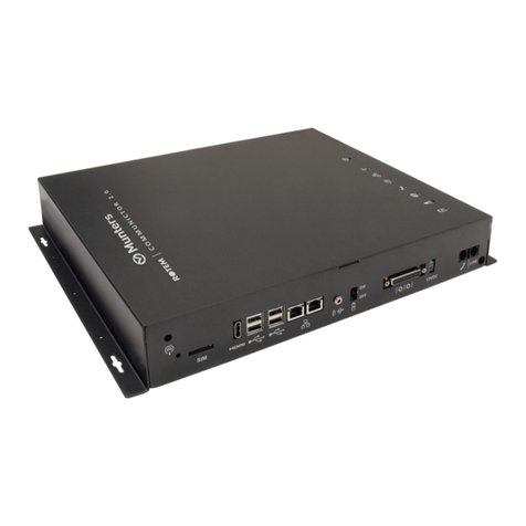
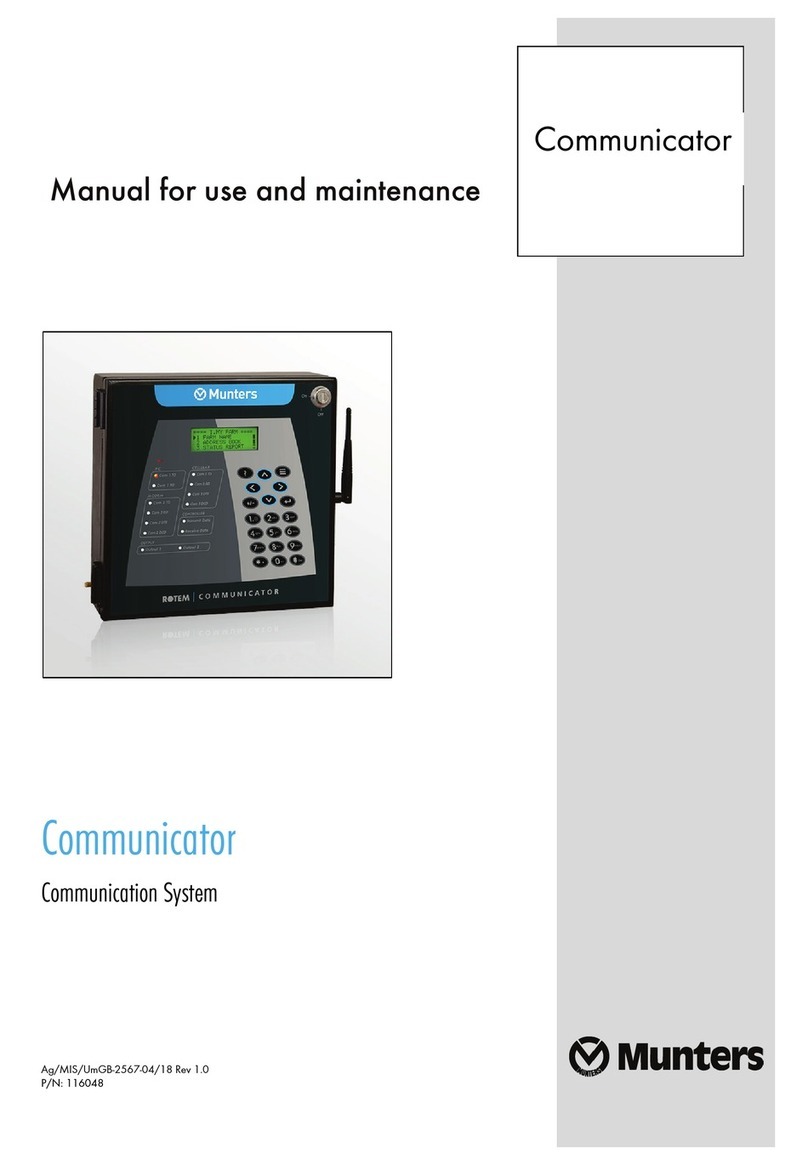
Munters Communicator 2.0 User manual

Installation and User Manual
Communicator 2.0 for Trio
Communication System
Ag/MIS/UmEn-2774-07/20 Rev 1.9
P/N: 116801
Communicator
2.0
for Trio

© Munters AB, 2020 Trio 2
Communicator 2.0 for Trio
Manual for use and maintenance
Document Revision: 1.9, 12/2023
Software Ver: 1.0.0.7
This manual for use and maintenance is an integral part of the apparatus together with the
attached technical documentation.
This document is destined for the user of the apparatus: it may not be reproduced in whole
or in part, committed to computer memory as a file or delivered to third parties without the
prior authorization of the assembler of the system.
Munters reserves the right to effect modifications to the apparatus in accordance with
technical and legal developments.

© Munters AB, 2020 Trio 3
Index
chapter page
1INTRODUCTION ................................................................................................................... 5
1.1 Disclaimer................................................................................................................ 5
1.2 Introduction ............................................................................................................ 5
1.3 Notes ....................................................................................................................... 5
2INTRODUCTION TO THE COMMUNICATOR 2.0............................................................. 6
3HARDWARE INSTALLATION............................................................................................. 7
3.1 Precautions ..............................................................................................................7
3.2 Communicator 2.0 Ports.........................................................................................7
3.3 Interior..................................................................................................................... 8
3.4 Mounting the Communicator 2.0.......................................................................... 9
3.5 Grounding ..............................................................................................................10
3.6 Connecting the Communicator 2.0 to the Internet .............................................11
3.7 Connecting the Communicator 2.0 to a Phone Line............................................11
3.8 Attaching the Antenna ..........................................................................................11
3.9 Connecting the Communicator 2.0 to a Peripheral Device ................................ 12
3.10 Connecting the T-Box to External Devices.......................................................... 12
3.11 Setting Up a Communicator 2.0 / Trio LAN ........................................................ 13
3.12 Enabling SMS Messages ....................................................................................... 15
3.13 Testing the Battery................................................................................................ 15
4SPECIFICATIONS ................................................................................................................16
5FUNCTIONALITY................................................................................................................. 17
5.1 Farm Settings ........................................................................................................ 17
5.2 Alarms ....................................................................................................................18
5.2.1 Editing the Settings..........................................................................................
19
5.2.2 Adding Contacts ...............................................................................................
21
5.2.3 Alarm and Events History..............................................................................
23
5.2.4 Digital Inputs.....................................................................................................
23
5.2.5 Disable Alarms .................................................................................................
25
5.2.6 Clear Alarms......................................................................................................
25
5.3 Responding to Alarms.......................................................................................... 25
5.3.1 Responding to an Audio Message...............................................................
25
5.3.1.1 Receiving the Message................................................................
26
5.3.1.2 Responding to the Alarm Message ............................................ 26
5.3.2 Responding to a Text Message ....................................................................
27

© Munters AB, 2020 Trio 4
5.3.2.1 Resetting the Siren .......................................................................
27
5.3.2.2 Resetting the Alarm .....................................................................
27
5.3.2.3 Acknowledging a Message ..........................................................
27
5.4 Testing the Communicator 2.0............................................................................ 28
5.5 Additional Functions............................................................................................ 28
5.5.1 Software Upgrade ...........................................................................................
28
5.5.2 Battery Status...................................................................................................
29
5.5.3 Controllers Connectivity................................................................................30
5.5.4 About Tab / Technical Support.....................................................................
31
6DIAGNOSTICS .................................................................................................................... 32
7APPENDIX A: CHANGING THE BATTERY ...................................................................... 33
8APPENDIX B: IT SETUP...................................................................................................... 35
8.1 IT Setup ................................................................................................................. 35
8.2 LAN Cable Information ........................................................................................ 36
8.2.1 Wire/Optical Ethernet Infrastructure Basics...........................................
36
8.2.2 Trio Connectivity: 100/1000 GBPS Ethernet Switch .............................
36
8.3 Typical Setups ........................................................................................................37
9WARRANTY ....................................................................................................................... 40

© Munters AB, 2020 Trio 5
1Introduction
1.1 Disclaimer
Munters reserves the right to make alterations to specifications, quantities, dimensions etc.
for production or other reasons, subsequent to publication. The information contained
herein has been prepared by qualified experts within Munters. While we believe the
information is accurate and complete, we make no warranty or representation for any
particular purposes. The information is offered in good faith and with the understanding
that any use of the units or accessories in breach of the directions and warnings in this
document is at the sole discretion and risk of the user.
1.2 Introduction
Congratulations on your excellent choice of purchasing a Trio Communicator 2.0!
In order to realize the full benefit from this product it is important that it is installed,
commissioned and operated correctly. Before installation or using the Communicator 2.0,
this manual should be studied carefully. It is also recommended that it is kept safely for
future reference. The manual is intended as a reference for installation, commissioning and
day-to-day operation of Munters equipment.
1.3 Notes
Date of release: October 2018
Munters cannot guarantee to inform users about the changes or to distribute new manuals
to them.
All rights reserved. No part of this manual may be reproduced in any manner whatsoever
without the expressed written permission of Munters. The contents of this manual are
subject to change without notice.

© Munters AB, 2020 Trio 6
2Introduction to the Communicator
2.0
Communicator 2.0 provides complete access to your Munters Trio controllers, with alarms
and events sent directly to your mobile device, PC, or tablet. From one computer, tablet, or
smartphone, you can manage an entire network.
•Web and Cloud-based access to controllers
oMultiple, simultaneous users have network access
•Multiple communication pathways:
oBuilt-in internet and telephone connectivity
oCellular modem enables wireless communication
•Plug ins:
oCell modem according to the user's region (3G Worldwide, 4G US, 4G
Worldwide)
oLine modem
NOTE Voice functions require a line modem.
•Supports Munters' Web Application and Smart Phone Application
•Programmable alarms
oText messages sent in a variety of languages
oAlarms and data in real time
•Test functions ensure the Communicator 2.0 works as required

© Munters AB, 2020 Trio 7
3Hardware Installation
This document details how to install Munters' Communicator 2.0 unit. Installation can
include the following:
•Precautions
•Communicator 2.0 Ports
•Interior
•Mounting the Communicator 2.0
•Grounding
•Connecting the Communicator 2.0 to the Internet
•Connecting the Communicator 2.0 to a Phone Line
•Attaching the Antenna
•Connecting the Communicator 2.0 to a Peripheral Device
•Connecting the T-Box to External Devices
•Setting Up a Communicator 2.0 / Trio LAN
•Enabling SMS Messages
•Testing the Battery
NOTE: After installing the unit, check the Diagnostics (page 32) to make sure that
everything is working as required.
3.1 Precautions
Observe the following precautions when using your unit.
•Keep the Communicator 2.0 as far as possible from heavy contactor boxes and
other sources of electrical interference.
•Do not connect communication wire shields, which go from one house to another
at both ends. Connect them at one end only. Connection at both ends can cause
ground loop currents to flow, which reduce reliability.
•The COM connection for communications is not the shield wire. The COM, RX and
TX wires must connect to each other at all controllers.
3.2 Communicator 2.0 Ports
Figure 1: External Ports

© Munters AB, 2020 Trio 8
Table 1: Ports Description
Number Description Number Description
1 Antenna mounting port (refer
to Attaching the Antenna, page
11
8 25 pin connector (Not in use)
2 SIM card (internal cell modem)
(refer to Enabling SMS
Messages, page 15)
9 12 VDC
3 HDMI port (computer screen)
(refer to Connecting the
Communicator 2.0 to a
Peripheral Device, page 12)
10 Audio out (external speaker)
4 USB ports (mouse, KBD) (refer
to Connecting the
Communicator 2.0 to a
Peripheral Device, page 12)
11 Internet line port(refer to
Connecting the Communicator 2.0
to the Internet, page 11)
5 LAN ports 12 Phone line port (refer to
Connecting the Communicator 2.0
to a Phone Line, 11)
6 Grounding (refer to Grounding,
page 10)
13 Power cord
7 Battery disconnection switch
3.3 Interior
Figure 2: Components

© Munters AB, 2020 Trio 9
Table 2: Component Description
Number Description Notes
1 Power Supply
2 Battery (refer to Appendix A: Changing the Battery,
page 33)
3 LED Board
4 Line Modem Card This card is under
the LED board
5 Not used
6 Board
7 Cell Modem
8 SSD Card
9
Main CPU
3.4 Mounting the Communicator 2.0
Figure 3: Dimensions (mm)
•Mount the unit using the four supplied screws.

© Munters AB, 2020 Trio 10
Figure 4: Mounting
3.5 Grounding
•Connect the ground cable to the dedicated ground terminal.
Figure 5: Grounding Schematic
CAUTION The Communicator 2.0 must be grounded at all times!

© Munters AB, 2020 Trio 11
3.6 Connecting the Communicator 2.0 to the Internet
•Connect the Communicator 2.0 to your Internet connection.
Figure 6: Internet Connection
3.7 Connecting the Communicator 2.0 to a Phone Line
Figure 7: Phone Line Connection
NOTE The telephone line-modem output connection wiring must provide double
insulation. Use minimum 26 AWG wiring or larger for telephone line connection.
3.8 Attaching the Antenna
If the Communicator 2.0 comes with a cell modem, attach the antenna.
Figure 8: Antenna Attachment

© Munters AB, 2020 Trio 12
3.9 Connecting the Communicator 2.0 to a Peripheral Device
•If required, connect a screen and key board to the Communicator 2.0 (via the four
USB or single HDMI ports).
NOTE: You’ll need to connect the Communicator 2.0 to these devices for the Activation.
Figure 9: Connection to Peripherals
3.10 Connecting the T-Box to External Devices
If required, connect the T-Box to external devices and an ELS system (Figure 11).
1. Plug the 25 plug connector into the T-Box.
Figure 10: Communicator 2.0 – Junction Box – Controller Block Diagram
2. Wire the devices as shown in Figure 11.

© Munters AB, 2020 Trio 13
Figure 11: T-Box Wiring Diagram with ELS
3.11 Setting Up a Communicator 2.0 / Trio LAN
Connect the Communicator 2.0 and Trio units via a local intranet.
NOTE The Communicator 2.0 and Trio units can be plugged into any port. The above
drawing is an example only.

© Munters AB, 2020 Trio 14
Figure 12: Trio Ethernet port
CAUTION Connect the intranet cable to port 2. Do not connect the cable to port 1.
1 Internal port (do not use this port)
2 Ethernet port
3 RJ-45 cable

© Munters AB, 2020 Trio 15
3.12 Enabling SMS Messages
•Sending SMS message requires a Communicator 2.0 having an internal modem
(supplied by Munters if ordered). This modem will support your cellular
infrastructure and region (4G US, 4G ROW, 3G)
•Insert a 3G or 4G standard SIM card as indicated:
Figure 13: SIM Port
3.13 Testing the Battery
CAUTION Munters highly recommends testing the battery immediately after
completing the installation!
1. Ensure that the battery is charged (Green LED should be on continuously). If the
LED blinks, wait.
2. Disconnect the AC power. Power LED turn red.
3. You should receive an alarm according to the contact list settings.
4. After receiving the alarm message, reapply power.

© Munters AB, 2020 Trio 16
4
Specifications
Power Supply
Mains Input Power 100 - 240 VAC, 50/60 Hz
Maximum Power Consumption 1.8A
Main Fuses
Main Fuse 230/115 VAC F1: 250 VAC/3 A
Battery Fuse F2: 1.85 A
Switching Power Supply F3: 1.1 A
Connection Box Peripherals
8 Digital Inputs Dry Contact, 5V / 2 mA
Relays Outputs
N.C/N.O. (OMI) Blue Small Low Power
Relay
5 Amps, 250 VAC
Alarm Output
N.O and N.C (Double) (OMI) Pilot Duty 5 Amps, 250 VAC
Environmental Specifications
•Indoor use only
•Altitude: -400 m to 2000 m
•Relative Humidity: 20% - 70%
•Main supply voltage fluctuation up to 5%
•Overvoltage category II
Housing
Metal Box Dimensions (L x W x H) 416 x 266 x 60 mm
Ambient Climate
Operating Temperature Range 0
°
to +35
°
C /
+
32
°
to
+
95
°
F
Storage Temperature Range -10
°
to +50
°
C /
+
14
°
to
+
125
°
F
Certification

© Munters AB, 2020 Trio 17
5Functionality
The following sections describe how to use the web functions.
•Farm Settings
•Alarms
•Responding to Alarms
•Testing the Communicator 2.0
•Additional Functions
5.1 Farm Settings
Use this screen to define functions related to Communicator 2.0’s connection to your farm.
•Farm Name: This name appears on your screen.
•Number of Trios to be Scanned: Click the -/+ buttons to enter the number of
houses. Scanning tests communication to the Trios. If you wish to scan all houses
or individual houses, click the relevant house number. Click Rescan farm houses to
complete the scan.
NOTE The number of units entered must match the actual number of units. If they differ,
an error message appears. Up to 64 houses can be scanned.
•Date and Time/Time Zone: Enter the information.
•Click Save Changes.

© Munters AB, 2020 Trio 18
5.2 Alarms
This section describes how to configure the alarms. All other functions are described in the
Platinum Touch manual.
•Alarms can only be configured locally. Anyone viewing the Communicator 2.0
screen via the web will not see Alarm System in the Settings icon.
•The alarm settings defined in these screens are general definitions that apply to all
alarms unless the alarm has a specific parameter that defines the setting. In that
case, the alarm parameter will override the alarm setting defined here.
•Extremely important: Set up a contact list after installing the unit. You must enter
the 1st contact’s name and email address in order to activate Communicator
2.0.0’s alarm functionality! This contact, once entered, cannot be deleted, only
edited.
•Editing the Settings
•Adding Contacts
•Alarm and Events History
•Digital Inputs
•Disable Alarms
•Clear Alarms

© Munters AB, 2020 Trio 19
5.2.1 EDITING THE SETTINGS
1. Click the Alarm Settings tab.
The screen displays the current alarm settings along with Communicator 2.0 parameter
settings.
2. To edit the Alarm Settings click .

© Munters AB, 2020 Trio 20
3. Edit the following parameters:
oAlarm Report Delay: To prevent you from being overloaded with insignificant
alarms, you can define the amount of time an alarm condition must continue
before an alarm is sent.
oUser Gap Time: Define the delay time (if any) between messages sent to the
next person on the list (see the Priority setting).
oMessage Repeat Delay: Alarms must be acknowledged or messages are
resent to the list. Define the amount of time in which acknowledgment must
take place before resending messages.
oTest Message Time: A test message can be sent daily to ensure that message
transmission is operating properly. This parameter sets the time that this
message is sent.
oCountry of installation: Choose from the drop down list.
oGenerator Ip Address (US customers only): Users having a backup generator
connected to the Communicator 2.0 can enter the generator’s IP address.
Communicator 2.0 will transmit any alarms from the generator.
oPhone Line alarm: Enable sending an alarm if the phone line is disconnected.
oLine-Out Volume: Define the call volume.
NOTE: The above two parameters require telephony connectivity to be enabled.
oVoice Speech Speed: Define the text-to-speech playback speed.
oAbout: These read-only parameters provide data for service technicians.
4. Click Save.
Other manuals for Communicator 2.0
2
Table of contents
Other Munters Conference System manuals
Popular Conference System manuals by other brands

Tobii Dynavox
Tobii Dynavox I-110 Getting started guide

Polycom
Polycom V500 Administrator's guide

Comrex
Comrex ACCESS STEREO BRIC IP manual

Mitel
Mitel MiVoice Business 3300 ICP troubleshooting guide

Toa
Toa Venas VM-2120 instruction manual

AT&T
AT&T MERLIN LEGEND Release 2.0 Analog Multiline... Equipment and operations guide